Page 1
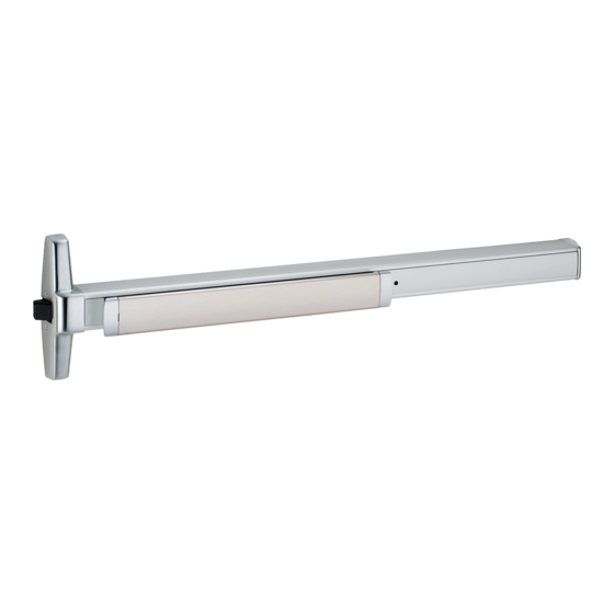
This instruction covers new installation of the 33/3549A concealed vertical device for aluminum and hollow metal doors. Also covered is the CS 33/3549A retrofit cabling system for converting 33/3547A Series to 33/3549A Series (compatible with models 33/3547A, 33/3547A-F, 33/3547A-LBR, and 33/3547A-F-LBR).
Identify Cables and Locations. NOTE: For retrofit installations, (if not preinstalled in door) begin at Step 5. CABLE IDENTIFICATION (STANDARD SIZES) HOLLOW METAL AND NARROW STILE WIDE STILE ALUMINUM DOORS ALUMINUM DOORS Door Opening For easy identification, Height Top Cable (Red) Bottom Cable (White) Top Cable (Red) Bottom Cable (White)
Page 3
Determine if Bottom Latch Retraction Adjustment is Adjust Bottom Latch Retraction (if necessary). Necessary. For 2-Point Latch Only For 2-Point Latch Only NOTE: Adjustment must be made while the top a. Flex the cable into an L-shape as shown to simulate the installed latch is in the hold-open position, with cable condition of the latches.
Page 4
If Retrofit Installation Assemble Latch Mounting Brackets. Hollow Metal a. Remove device b. Remove and c. Remove and ³⁄₄" mounting from existing discard existing discard existing door. door. strikes. shown 3/4" 1/4" With Door Laying Flat, Draw Horizontal and Vertical 3/4"...
Page 5
If Necessary, Prepare Door for Top Strike Cutout. If Using 360/386/388 Thru-Bolting Trim, Remove Center Slide Mounting Nut. 1¹⁄₄" Cut out material this side only Thru-bolting trim uses standoffs (360L trim shown) ⁹⁄₁₆" Latch Push side of door, RHR shown Prepare Top of Door for Latch Mounting.
Page 6
Secure Center Slide to Door. Align Bottom Latch and Install Mounting Screws. Aluminum For 2-Point Latch Only Secure center slide to door by lightly tightening lower screw Align upper hole visually Secure Top Latch with 2 Screws. Aluminum Insert small screwdriver into upper hole to prevent center slide from rotating...
Page 7
Insert Latch Adjustment Pin to Hold Bottom Latch If Necessary, Cut Device. in Place. Hollow Metal For 2-Point Latch Only Door Pin must go thru 1¹⁄₂" (38 mm) both sides Recommended of bracket Temporarily Remove Anti-Rattle Clip Bottom edge of latch housing should be flush with bottom of door (for ³⁄₈"...
Page 8
Mark and Prepare 2 Holes. If Retrofit Installation, Install Steel Cover Plate to Cover Existing 338 Strike Opening in Accordance with the Frame Manufacturer’s Fire Listing. Surface Mount (metal doors only) #10-24 Strike Filler Plate (3FP0116A001-GL) purchased separately Sex Bolts Install 2 Top Strike Screws Using the Slot Features on the Strike.
Page 9
Install Bottom Strike. Install Lift Finger and Retainer Clip. Hollow Metal For 2-Point Latch Only NOTE: The lift finger installation and adjustment must be performed while the latches are in the extended (latched) position. Clear holes of debris, then Secure the anchors using a drop in anchors (slotted end hammer and punch Slide L-shaped lift finger thru block in...
Third Strike Screw to Fix the Strike Position. a. Depress pushbar. Door should begin to open when pushbar is nearly fully depressed. If necessary, refer to Step 33 to readjust lift finger. Metal b. With door closed, top latch should be secure.
Page 11
C Latch ALUMINUM AND HOLLOW METAL DOORS - RHR B = backset A = stile width 33/3549A Device Template 33/3549A Installation 2¹⁄₈" to 2³⁄₄" 1³⁄₁₆" pair of doors 2³⁄₄" to 3³⁄₄" 1¹⁄₂" 3³⁄₄" to 5" 1⁷⁄₈" 5" to flush 2¹⁄₂"...
Page 12
Latch C ALUMINUM AND HOLLOW METAL DOORS - LHR B = backset 33/3549A Device Template A = stile width 33/3549A Installation 2¹⁄₈" to 2³⁄₄" 1³⁄₁₆" pair of doors 2³⁄₄" to 3³⁄₄" 1¹⁄₂" 3³⁄₄" to 5" 1⁷⁄₈" 5" to flush 2¹⁄₂"...
Need help?
Do you have a question about the 33 and is the answer not in the manual?
Questions and answers