Von Duprin 99 Installation Instructions Manual
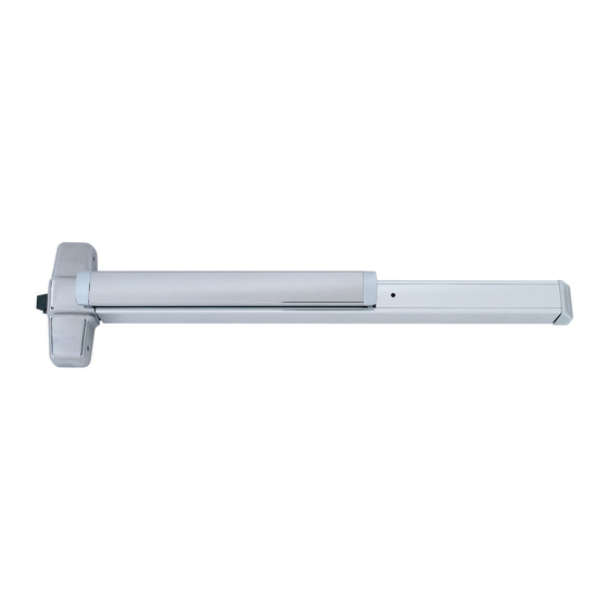
Rim exit device
Hide thumbs
Also See for 99:
- Installation instructions manual (8 pages) ,
- Installation instructions manual (9 pages)

Related Manuals for Von Duprin 99


Summary of Contents for Von Duprin 99
- Page 1 98/99 911373-00 Rim Exit Device Installation Instructions #10-24 Dogging Key (use to lock down pushbar) Customer Service © Allegion 2014 Printed in U.S.A. 911373-00 Rev. 01/14-e 1-877-671-7011 www.allegion.com...
- Page 2 SCREW CHART Screw Application Device Subassembly #10-24 x ³⁄₄” (19 mm) Metal frame Wood frame #10 x 1¹⁄₂” (38 mm) Wood screw 299 Strike 499F Strike Surface mount or Sex bolts #10-24 x 1” (25 mm) 1³⁄₄” (44 mm) door #10-24 x 1¹⁄₂”...
- Page 3 Mark Vertical C L For more information on the strikes shown below, go to Mark 6 holes http://w3securitytechnologies.com and look for the Support area for Von Duprin installation instructions. If necessary, prepare cutouts for cylinder and trim. 1439 1609 RHR shown, LHR opposite...
- Page 4 With the NL drive screw installed, key retracts latch bolt. DO NOT remove NL drive screw for the following applications: See trim instructions NL, EO, DT trims and 98/99-2 double cylinder devices (i.e. TP-2, for pull side door L-2, and K-2).
- Page 5 If necessary, cut device. Mark and prepare two (2) holes. Prepare holes after lock side of device is mounted and hinge side is leveled. SURFACE MOUNT 1¹⁄₂” (38 mm) recommended #10-24 ¹⁄₈” (3 mm) x 1” (25 mm) Deep Temporarily remove anti-rattle clip SEX BOLTS ¹⁄₄”...
- Page 6 Install required support screws and Adjust strike as needed. center case cover. Shim as needed 299/299F Strike Remove protective fi lm from pushbar ³⁄₁₆” (5 mm) 299F Install strike support screw. METAL WOOD ¹⁄₈” (3 mm) x 1” (25 mm) Deep #10-24 499F STRIKE INSTALLATION 1.
- Page 7 OPTIONAL EQUIPMENT CD (Cylinder Dogging) Option Undog...
- Page 8 (41 mm) ¹³⁄₁₆” (21 mm) 1³⁄₈” (35 mm) Device and Strike For 98/99-2SI models with Classroom Security Indicator, apply supplied labels above and below cylinder to match door handing, label on indicator. 99-2 99-2 Peel and stick appropriate set of labels depending on door handing.
Need help?
Do you have a question about the 99 and is the answer not in the manual?
Questions and answers