Advertisement
Quick Links
*941369-00*
941369-00
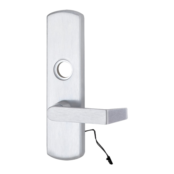
Motorized Locking Trim
M996L
for Rim/Vertical
1
Retrofit / replace operation if necessary.
2
Change function (Fail Safe or Fail Secure) if necessary.
!
Product is shipped in Fail Safe (FS) configuration. Fail Safe configuration is required by code in some applications (typically fire
stairwells). Consult building codes before converting to Fail Secure (FSE) configuration. See page 8 for FS/FSE function information.
2.1. To change function, use the tip of a small screwdriver to CAREFULLY move the switch to the desired position. The
switch is factory set to fail safe (FS). Moving the switch changes the function to fail secure (FSE). After changing FS/FSE
switch position, power cycle the unit two or more times before installation. See Figure 2-1.
Unit locks when electric
power is applied and
unlocks when power is
M996L Series
M996L
for Mortise
FS (fail safe)
factory setting
removed
⁵⁄₁₆" Nut driver
#2 Phillips
(See M996L Series Retrofit, 941389-00)
CAUTION
Fig. 2-1
Installation Instructions
Parts Included
M996 Motorized Module
Tools Needed
FSE (fail secure)
Unit unlocks when
electric power is applied
and locks when power
is removed
Advertisement

Related Manuals for Von Duprin M996L Series


Summary of Contents for Von Duprin M996L Series
- Page 1 Rim/Vertical for Mortise Retrofit / replace operation if necessary. (See M996L Series Retrofit, 941389-00) Change function (Fail Safe or Fail Secure) if necessary. CAUTION Product is shipped in Fail Safe (FS) configuration. Fail Safe configuration is required by code in some applications (typically fire stairwells).
- Page 2 Connect trim plug to cable plug (See Figure 12-1). Page 2 of 8...
- Page 3 Check exit device NL drive screw. For rim/vertical device applications, make sure the NL drive screw is installed in the exit device center case cam with the exit device lock slide in the up position. See figure 4-1 for LHR applications and Figure 4-2 for RHR applications.
- Page 4 Prepare holes and cut-outs on door. 5.1. Prepare exit device side of door using instructions and template provided with exit device. 5.2. Prepare trim side of door using dimensions on front side of instruction sheet 921003/921006. Drill and deburr 3/8” dia.
- Page 5 Route E996L cable through 98/99 series exit device. 7.1. Remove two mechanism case screws (Figure 7-1). 7.2. Slide mechanism case off baseplate assembly (Figure 7-2). 7.3. Route E996L cable through center case slots as shown (Figure 7-1). Cable plug should be on door side of center case as shown (Figure 7-1).
- Page 6 9.3. Route cable through door and attach wiring to power transfer. (Figure 9-2). Note: EPT recommended for new construction; electric hinge or door loop recommended for retrofit. Mounting bracket Power transfer (Von Duprin EPT2 shown) Cable in hole Fig. 9-1 Fig. 9-2...
- Page 7 Attach center case to door. 10.1. Support hinge side of device in mounting bracket. 10.2. If trim has been temporarily installed, remove 4 screws in center case and remove trim. 10.3. Pull center case away from door and route E996L cable plug through wire access hole in door (Figure 10-1).
- Page 8 Basic wiring information. Power control requirements. The two wires are non-polarized 12/24 VDC input. One wire connects directly to a 12/24 VDC power source (power supply) and the other wire connects to a control device (card reader, key pad, push button, dry contact, etc.) and then to the power supply.
Need help?
Do you have a question about the M996L Series and is the answer not in the manual?
Questions and answers
I need this hooked up to a card reader or FOB access
To connect the Von Duprin M996L Series to a card reader or FOB access:
1. Use the two non-polarized 12/24 VDC input wires from the device.
2. Connect one wire directly to the 12/24 VDC power supply.
3. Connect the other wire to the output of the card reader, keypad, push button, or other control device, then to the power supply.
Ensure the power supply provides at least 1A. Route the wires so they do not get pinched or interfere with device rods or slider.
This answer is automatically generated