Table of Contents
Advertisement
911404-00
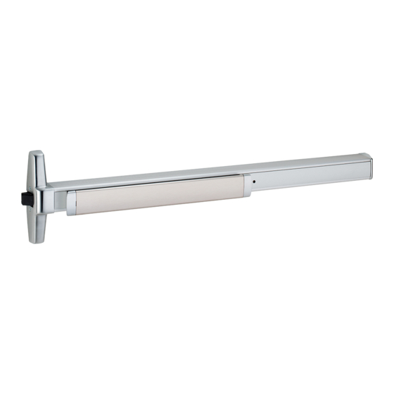
Concealed Vertical Rod Exit Device
33/3547A-F and 33/3548A-F Fire Concealed Vertical Rod Exit Device
CD33/3547A and CD33/3548A Concealed Vertical Rod Exit Device
EL33/3547A and EL33/3548A Concealed Vertical Rod Exit Device
Devices covered by these instructions:
33/3547A and 33/3548A Concealed Vertical Rod Exit Device
1-877-671-7011
33/3547A
Special tools needed:
#10-24 tap
Drill bits: #25, 5/16",
Screw chart ............................ 2
Device installation ................ 3-5
Adjust rods ............................. 6
Frame preparation .................. 7
Optional equipment ................. 8
Backset information ................ 9
Metal door templates . ....... 11-12
Wood door preparation .... 13-14
Wood door templates ...... 15-16
Customer Service
www.allegion.com
Installation Instructions
13/32", 1/2"
Index:
911404-00 Rev. 01/14-c
© Allegion 2014
Printed in U.S.A.
Advertisement
Table of Contents


Need help?
Do you have a question about the 33 and is the answer not in the manual?
Questions and answers