Advertisement
RSPSupply - 1-888-532-2706 - www.RSPSupply.com
http://www.RSPSupply.com/p-9305-Moxa-ICF-1170I-M-ST.aspx
ICF-1170I Series
Quick Installation Guide
First Edition, September 2009
© 2009 Moxa Inc. All rights reserved.
Reproduction without permission is prohibited.
Fl.4, No.135, Lane 235, Pao-Chiao Rd.
Shing Tien City, Taipei, Taiwan, R.O.C.
TEL: +886-2-8919-1230
P/N: 1802011700010
Advertisement
Table of Contents

Related Manuals for Moxa Technologies ICF-1170I Series


Summary of Contents for Moxa Technologies ICF-1170I Series
- Page 1 ICF-1170I Series Quick Installation Guide First Edition, September 2009 © 2009 Moxa Inc. All rights reserved. Reproduction without permission is prohibited. Fl.4, No.135, Lane 235, Pao-Chiao Rd. Shing Tien City, Taipei, Taiwan, R.O.C. TEL: +886-2-8919-1230 P/N: 1802011700010 RSPSupply - 1-888-532-2706 - www.RSPSupply.com...
- Page 2 EMI. The ICF-1170I series can separate and protect critical segments of the system from the rest of the CAN network and is protocol independent, allowing it to work with all of the different CAN protocols and frame lengths.
-
Page 3: Package Checklist
The ICF-1170I supports dual power inputs for redundancy. When one power input fails, the relay will be triggered. Be sure to install the dual power inputs for the ICF-1170I series, and choose the correct relay output when connecting the alarm. -
Page 4: Mounting Dimensions (Unit: Mm)
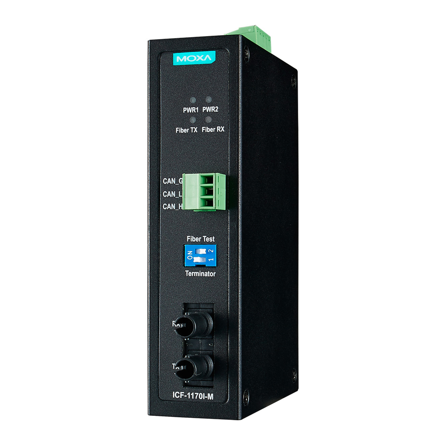
Mounting Dimensions (Unit: mm) ICF-1170-M-ST Top View Front View RS-422/485 OP Mode Switch Fiber Port ATTENTION Electrostatic Discharge Warning! To protect the product from damage due to electrostatic discharge, we recommend wearing a grounding device when handling your ICF-1170 series. - 4 - RSPSupply - 1-888-532-2706 - www.RSPSupply.com http://www.RSPSupply.com/p-9305-Moxa-ICF-1170I-M-ST.aspx... -
Page 5: Fiber Cable
The aluminum DIN-Rail attachment plate should be fixed to the back panel of the ICF-1170I series when you take it out of the box. If you need to reattach the DIN-Rail attachment plate to the ICF-1170I, make sure the stiff metal spring is situated towards the top, as shown in the figures below. -
Page 6: Led Indicators
LED Indicators There are 4 LEDs on the front panel of the ICF-1170I. Color Function PWR 1 Green Steady ON: Power source 1 is ON. PWR 2 Green Steady ON: Power source 2 is ON. Fiber Tx Green When sending CAN data to the fiber port. Fiber Rx Orange When receiving data from the fiber port. -
Page 7: Ordering Information
-40 to 85°C (-40 to 167°F) for T model Storage Temperature -40 to 85°C (-4 to 185°F), 5 to 95 % RH Power Input Power Voltage 12 to 48 VDC dual power input for redundant power Alarm contact 1 relay output with current carrying of 1 A@24VDC Mechanical Specifications Dimensions...
Need help?
Do you have a question about the ICF-1170I Series and is the answer not in the manual?
Questions and answers