
Subscribe to Our Youtube Channel
Related Manuals for ACP RFS12MPSB


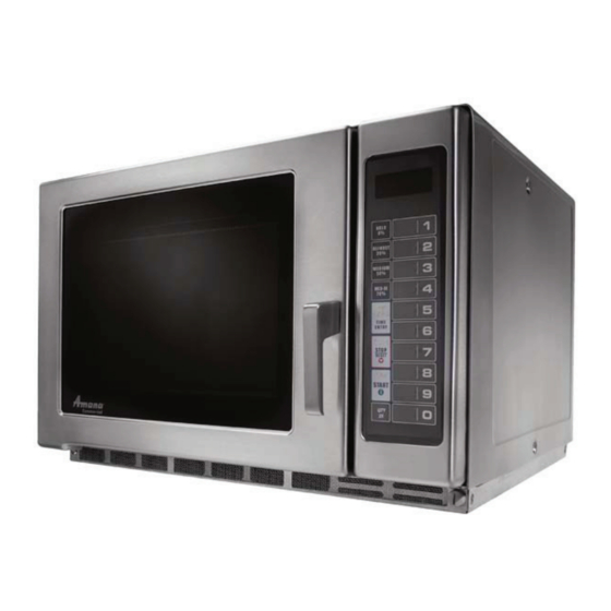
Summary of Contents for ACP RFS12MPSB
- Page 1 ______________ Service Manual Commercial Microwave Oven RFS12MPSB P1330235M RFS12SW2B P1330236M RFS12SW2C P1330237M 60 Hz July 2010 16400007...
-
Page 2: Important Information
Important Notices for Servicers and Consumers ACP will not be responsible for personal injury or property damage from improper service procedures. Pride and workmanship go into every product to provide our customers with quality products. It is possible, however, that during its lifetime a product may require service. -
Page 3: Table Of Contents
Cavity Thermal Fuse ..........27 Measurement With a Fully Assembled Oven ... 15 Tray Replacement ............ 27 Record Keeping and Notification Oven Light Removal ..........27 After Measurement ..........15 Testing Procedures ..........16-19 Power Test ..............20 16400007 Rev. 0 ©2010 ACP, Inc. -
Page 4: Important Safety Information
1. Always operate the unit from an adequately switches there is not valid reason for this action grounded outlet. Do not operate on a two-wire at any time; nor will it be condoned by ACP. extension cord. 9. IMPORTANT: Before returning a unit to a 2. -
Page 5: Save These Instructions
Remove wire twist-ties from paper or plastic bags before placing bag in oven. d. DO NOT use the cavity for storage. DO NOT leave paper products, cooking utensils, or food in oven. SAVE THESE INSTRUCTIONS 16400007 Rev. 0 ©2010 ACP, Inc. -
Page 6: Precautions To Avoid Possible Exposure
The oven should NOT be adjusted or repaired face and the door or allow soil or cleaner by anyone except properly quali ed service residue to accumulate on sealing surfaces. personnel. SAVE THESE INSTRUCTIONS 16400007 Rev. 0 ©2010 ACP, Inc. -
Page 7: Grounding Instructions
Models operate with a 120 supply voltage. When an oven is on a circuit with other equipment, an increase in cooking times may be required and fuses can be blown. NEMA 5-20R/5-20P 120V–20AMP 16400007 Rev. 0 ©2010 ACP, Inc. -
Page 8: General Information
Proper air flow around equipment cools electrical components. With restricted air flow, oven may not operate properly and life of electrical parts is reduced. Radio Interference Microwave operation may cause interference to radio, television, or similar equipment. Reduce or eliminate interference by doing the following: • Place radio, television, etc. as far as possible from oven. • Use a properly installed antenna on radio, television, etc. to obtain stronger signal reception. 16400007 Rev. 0 ©2010 ACP, Inc. -
Page 9: Troubleshooting Procedures
Inconsistent intensity of Uneven cooking. 2. Stir once or twice while microwave by their cooking soup, cocoa or characteristics. milk, etc. See Service Test Mode page 17 Display “CALL SERVICE” to clear CALL SERVICE . 16400007 Rev. 0 ©2010 ACP, Inc. - Page 10 3. Display shows a Still have trouble. assembly. assembly. number or gure di erent from one touched. 4. Random programming when touching other pads. 5. Display is xed at some gure and can not accept any input. 16400007 Rev. 0 ©2010 ACP, Inc.
- Page 11 2. Fuse does not Defective Replace No continuity. Check continuity blow. oven TCO. oven TCO. of oven TCO. Continuity. Check continuity Defective power Replace power No continuity. of power supply supply cord. supply cord. cord. 16400007 Rev. 0 ©2010 ACP, Inc.
- Page 12 Decrease in power Output is low. contact local rating voltage. power source source voltage electric power voltage. with load. utility co. or Normal. quali ed electrician. Measure the Defective Replace Abnormal. output power. magnetron. magnetron. 16400007 Rev. 0 ©2010 ACP, Inc.
- Page 13 Defective PCB Replace PCB Output is full power Disconnect the Abnormal. assembly. assembly. wire leads from when you set lower relay 3,5 and check power level. continuity of relay 3,5 (Operate the unit) 16400007 Rev. 0 ©2010 ACP, Inc.
-
Page 14: Service Information
R.F. Capacitors - May short to chassis. This condition will also cause loss of high voltage. Output Antenna Ceramic Fins Anode Block Magnet Terminals/R.F. Capacitors Not Replaceable Serial Number 16400007 Rev. 0 ©2010 ACP, Inc. -
Page 15: Microwave Leakage Test
(5 cm) spacer supplied with the probe. 4. Press the start pad or turn on the timer and with the magnetron oscillating, measure the leakage by holding the probe perpendicular to the surface being measured. 16400007 Rev. 0 ©2010 ACP, Inc. -
Page 16: Testing Procedures
Power In terminals ........120 VAC Power Out terminals ....... 120 VAC If no power in, check power outlet. If no power out, check fuses. Circuit Protector Measure resistance across terminals ..Between Terminals: Less than 1 Ω 16400007 Rev.0 ©2010 ACP, Inc. - Page 17 Press Pad 9..........Press Pad 0..........Exit Service Test Mode Stop/Reset Pad ..........Replace Control Board Error codes: E-08.............. Replace Control Board E-09.............. Shorted or Open Keypad – Test E-10.............. and replace if necessary 16400007 Rev. 0 ©2010 ACP, Inc...
- Page 18 Continuity DEFROST 2 & 10 Continuity (20%) 3 & 10 Continuity MEDIUM (50%) 4 & 10 Continuity MED-HI (70%) 5 & 10 Continuity TIME ENTRY 6 & 10 Continuity STOP/RESET 7 & 10 Continuity START 16400007 Rev.0 ©2010 ACP, Inc.
- Page 19 Relay 3 – Pin 1 to Pin 2 ......120 VAC Ready....Volts Relay 3 – Pin 1 to Pin 2 ......120 VAC Cook....Volts Relay 3 – Pin 1 to Pin 2 ......0 VAC 16400007 Rev. 0 ©2010 ACP, Inc...
-
Page 20: Power Test
13.... 2400 17 ....1700 25 ....2500 9.5 .... 1700 13.5..2500 18 ....1800 27 ....2700 10 ..... 1800 15.... 2700 19 ....1900 30 ....3000 10.5 ..1900 16.5..3000 16400007 Rev.0 ©2010 ACP, Inc. -
Page 21: Disassembly Procedures
Outer Case 1. Disconnect power to oven. 2. Remove screws securing outer case to unit. 3. Slide outer case towards rear of unit. 4. Reverse procedure to reassemble. 16400007 Rev. 0 ©2010 ACP, Inc. -
Page 22: Door Assembly
Gently pry upward on choke cover to release tabs. Work in clockwise direction to remove choke cover. CAUT IO N A microwave leakage test must be performed anytime a door assembly is removed, replaced, disassembly, or adjusted for any reason. 16400007 Rev. 0 ©2010 ACP, Inc. -
Page 23: Control Removal
3. Test interlock switches before removing, (see testing Adjusting Interlocks procedures). The interlock monitor, primary, and secondary switches act as a final safety switch, protecting the operator from microwave energy. After adjusting the interlock switch assembly, verify wires are correctly connected. For door fit and switch operation, switch bracket is adjustable. 16400007 Rev. 0 ©2010 ACP, Inc. -
Page 24: Capacitor
Before replacing a blown monitor fuse, test the primary interlock switch, secondary interlock switch, monitor switch, and power relay contacts for proper operation. If the monitor fuse is blown by a failed switch operation, interlock assembly must be replaced. 16400007 Rev. 0 ©2010 ACP, Inc. -
Page 25: Magnetron
During replacement of magnetron, be certain the R.F. anode gasket is in place around the anode stud. WARNING A microwave leakage test must be performed anytime a magnetron assembly is removed, replaced, disassembled, or adjusted for any reason. 16400007 Rev. 0 ©2010 ACP, Inc. -
Page 26: Splatter Shield
3. Remove two mounting rivets on the bottom of oven cavity floor to remove cradle. Support cradle before removing mounting rivets to avoid damage to Base cover antenna assembly. Taptite Screw Wire Leads Stirrer Fan Motor 16400007 Rev. 0 ©2010 ACP, Inc. -
Page 27: Magnetron Thermal Cut-Out (Tco)
4. Clean oven cavity bottom where new oven tray will make contact using mineral spirits or any non-flammable degreasing solvent. NOTE: Detergents, soap, and water are not sufficient to remove oil and grease. 5. Place new tray into unit and clean cavity with mild detergent to remove any remaining degreasing solvant. 16400007 Rev. 0 ©2010 ACP, Inc.
Need help?
Do you have a question about the RFS12MPSB and is the answer not in the manual?
Questions and answers