Advertisement
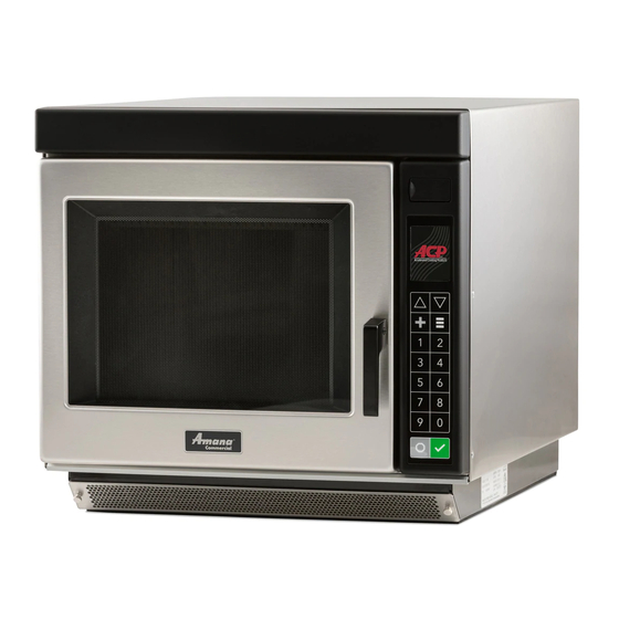
Commercial Microwave—Technical Information
208/230 VAC, 60 Hz Models
RC17S2
RC17SDOSI
DQ22HSI
MC23MPTW2
KFC2W2
• Due to possibility of personal injury or property damage, always contact an authorized technician for servicing or
repair of this unit.
• Refer to Service Manual for installation, operating, testing, troubleshooting, and disassembly instruction.
All safety information must be followed as provided in Service Manual.
To avoid the risk of electrical shock, personal injury or death; disconnect power to oven and discharge capacitor
before servicing, unless testing requires power.
Models
RC17SX
RC17SD2OSII
Power Source
Voltage AC
208/230 VAC
Amperage (Single
Unit)
Frequency
Single Phase, 3 wire
grounded
Receptacle
Plug
Power Output −
Microwave
Nominal microwave
1700 Watts
energy (IEC705)
Operating Frequency
2450 MHz
Power Consumption
Microwave only
2700 Watts
Dimensions
Cabinet (in cm)
Width
19 1/4"
Height
18 1/4"
Depth
26 1/4"
Oven Interior (in cm)
Width
13"
Height
8 1/2"
Depth
15"
Weight
Uncrated
Crated
** MC23MPTW2, MC23MPW2 uses 20A Twist−Loc NEMA L6-20P plug
January 2012
©2012 ACP, Inc.
P1333401M
P1333403M
P1333405M
P1333407M
P1333409M
!
!
RC17S2
RC22S2
DQ22HSI2
WDYRC22
208/230 VAC
20 A
20 A
60 Hz
60 Hz
X
X
6-20R
6-20R
6-20P
6-20P
2200 Watts
2450 MHz
3200 Watts
49 cm
19 1/4"
49 cm
46 cm
18 1/4"
46 cm
67 cm
26 1/4"
67 cm
33 cm
13"
33 cm
22 cm
8 1/2"
22 cm
38 cm
15"
38 cm
94 lbs.
94 lbs.
101 lbs.
101 lbs.
RC17SX
RC22S2
MC23MPW2
WDYRC22
RC30S2
CAUTION
WARNING
RC30S2
KFC2W2
208/230 VAC
208/230 VAC
30 A
30 A
60 Hz
60 Hz
X
6-30R
6-30R
6-30P
6-30P
3000 Watts
2700 Watts
2450 MHz
2450 MHz
4400 Watts
4100 Watts
19 1/4"
49 cm
19 1/4"
18 1/4"
46 cm
18 1/4"
26 1/4"
67 cm
26 1/4"
13"
33 cm
13"
8 1/2"
22 cm
8 1/2"
15"
38 cm
15"
115 lbs.
115 lbs.
123 lbs.
123 lbs.
1
P1333402M
P1333404M
P1333406M
P1333408M
P1333410M
MC23MPTW2
MC23MPW2
208/230 VAC
20 A
60 Hz
X
X
**
**
2000 Watts
2450 MHz
3200 Watts
49 cm
19 1/4"
49 cm
46 cm
18 1/4"
46 cm
67 cm
26 1/4"
67 cm
33 cm
13"
33 cm
22 cm
8 1/2"
22 cm
38 cm
15"
38 cm
115 lbs.
123 lbs.
16500030
Advertisement
Table of Contents

Related Manuals for ACP P1333401M


Summary of Contents for ACP P1333401M
- Page 1 38 cm Weight Uncrated 94 lbs. 94 lbs. 115 lbs. 115 lbs. 115 lbs. Crated 101 lbs. 101 lbs. 123 lbs. 123 lbs. 123 lbs. ** MC23MPTW2, MC23MPW2 uses 20A Twist−Loc NEMA L6-20P plug January 2012 16500030 ©2012 ACP, Inc.
-
Page 2: Component Testing Procedures
Note: This test is not conclusive. If oven does not heat and all other components test good replace the magnetron and retest. Blower motor Remove all wires from motor. Approximately 25 Ω Measure resistance across coil ....16500030 January 2012 ©2012 ACP, Inc. - Page 3 Terminal to terminal ........Approximately 12K Ω Refer to Parts Manual Power cord Measure resistance of wires. Continuity should be indicated on for proper power cord each wire. part number. Verify polarity and grounding. January 2012 16500030 ©2012 ACP, Inc.
- Page 4 Volts Test points A and B 3.0 VAC Board Board If voltage is present and no display is indicated, replace display board. If no voltage is present, check wire harness connections and H.V. board. 16500030 January 2012 ©2012 ACP, Inc.
- Page 5 J1 pin 1 (Brown wire) Test mode 5 off − no continuity 208 VAC Antenna motor J2 connector & J2 pin 3 Test mode 5 on − < 1 Ω line voltage Cavity light January 2012 16500030 ©2012 ACP, Inc.
- Page 6 Test mode 3 off − line voltage Magnetron 3 All wires J4 pin 4 (Black wire) (Bottom) at connected to & J4 pin 5 (Brown wire) Test mode 3 on − 0 volts 208 VAC H.V. board 16500030 January 2012 ©2012 ACP, Inc.
- Page 7 H.V. System # 3 Top Rear Magnetron Top Front Magnetron Bottom Magnetron Center Transformer Left Transformer Right Transformer Bottom Center Capacitor Top Left Capacitor Right Capacitor Diode Diode Diode Center Triac Left Triac Right Triac January 2012 16500030 ©2012 ACP, Inc.
- Page 8 Two Magnetron Models H.V. System # 1 H.V. System # 3 Top Rear Magnetron Bottom Magnetron Left Transformer Right Transformer Top Capacitor Bottom Capacitor Diode Diode Left Triac Right Triac 16500030 January 2012 ©2012 ACP, Inc.
-
Page 9: Power Testing Procedure
Using the test shown below will indicate if the oven performance is satisfactory. Test equipment required: • 1000 ml test container and thermometer (ACP power test bowl part # 12018801). • Digital watch / watch with a second hand for use on ovens with electromechanical timers. -
Page 10: Display Diagnostics
Door Interlock Primary Switch Verify latch mechanism moves freely on door. • Verify J1 connector on display board is properly seated. • Test interlock switch assembly and perform door adjustment if necessary. • Replace interlock switch assembly. 16500030 January 2012 ©2012 ACP, Inc. -
Page 11: Service Test
Note: Not applicable on two magnetron models: Pad 3 Mode Name Service Pad 3 Pressing Pad 3 while in Service Mode Entry Functional Magnetron #3 shall be toggled. When on, it shall run for 62 seconds. Description Display January 2012 16500030 ©2012 ACP, Inc. - Page 12 Displays Door Cycles stored in EEPROM. Will always be a multiple of Functional Description ten. Display Pad 9 Mode Name Service Pad 9 Entry Pressing Pad 9 while in Service Mode Functional Prompts user to clear service information. Description Display 16500030 January 2012 ©2012 ACP, Inc.
- Page 13 Service Test 12719301 DQ22HSI2 RC17S2 RC17SX RC22S2 January 2012 16500030 ©2012 ACP, Inc.
-
Page 14: Wiring Diagram And Schematic
Wiring Diagram and Schematic W ARNING To avoid risk of electrical shock, personal injury or death; disconnect power to oven and discharge capacitor before servicing, unless testing requires power. 12719301 DANGER HIGH VOLTAGE DQ22HSI2 RC17S2 RC17SX RC22S2 16500030 January 2012 ©2012 ACP, Inc. - Page 15 Wiring Diagram and Schematic W ARNING To avoid risk of electrical shock, personal injury or death; disconnect power to oven and discharge capacitor before servicing, unless testing requires power. 12719101 KFC2W2 MC23MPW2 MC23MPTW2 RC30S2 January 2012 16500030 ©2012 ACP, Inc.
- Page 16 Wiring Diagram and Schematic W ARNING To avoid risk of electrical shock, personal injury or death; disconnect power to oven and discharge capacitor before servicing, unless testing requires power. 12719101 DANGER HIGH VOLTAGE KFC2W2 MC23MPW2 MC23MPTW2 RC30S2 16500030 January 2012 ©2012 ACP, Inc.
Need help?
Do you have a question about the P1333401M and is the answer not in the manual?
Questions and answers