Table of Contents
Advertisement
Quick Links
Advertisement
Table of Contents

Related Manuals for Advantech ARK-3202V -S6A1E


Summary of Contents for Advantech ARK-3202V -S6A1E
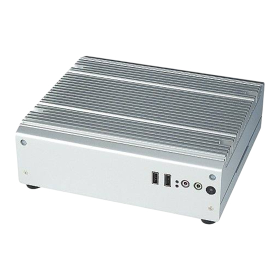
- Page 1 User Manual ARK-3202V Compact Embedded IPC...
- Page 2 The documentation and the software included with this product are copyrighted 2011 by Advantech Co., Ltd. All rights are reserved. Advantech Co., Ltd. reserves the right to make improvements in the products described in this manual at any time without notice.
- Page 3 Because of Advantech’s high quality-control standards and rigorous testing, most of our customers never need to use our repair service. If an Advantech product is defec- tive, it will be repaired or replaced at no charge during the warranty period. For out- of-warranty repairs, you will be billed according to the cost of replacement materials, service time and freight.
- Page 4 Technical Support and Assistance Visit the Advantech web site at www.advantech.com/support where you can find the latest information about the product. Contact your distributor, sales representative, or Advantech's customer service center for technical support if you need additional assistance. Please have the following information ready before you call: –...
- Page 5 Safety Instructions Read these safety instructions carefully. Keep this User Manual for later reference. Disconnect this equipment from any AC outlet before cleaning. Use a damp cloth. Do not use liquid or spray detergents for cleaning. For plug-in equipment, the power outlet socket must be located near the equip- ment and must be easily accessible.
- Page 6 1 x Utility CD 1 x Registration and 2 years Warranty card Ordering Information Model Number Description Intel® ATOM N270 1.6 GHz Compact Embedded Box IPC, ARK-3202V -S6A1E with 2 MiniPCIe , on-board GPS, and 5 COM Optional Accessories Part Number Description 1757003659 ADAPTER AC 65W DC19V/3.42A FSP065-RAC...
-
Page 7: Table Of Contents
Contents Chapter General Introduction ......1 Introduction ....................2 Product Feature ..................2 1.2.1 General ..................2 1.2.2 Display ..................2 1.2.3 Power Consumption..............2 Hardware Specification ................2 1.3.1 System ..................2 1.3.2 Memory ..................3 1.3.3 Input/Output .................. 3 1.3.4 Graphics.................. - Page 8 BIOS Setup ..................... 30 3.2.1 Main Menu .................. 31 3.2.2 Standard CMOS Features ............32 3.2.3 Advanced BIOS Features ............33 3.2.4 Advanced Chipset Features ............34 3.2.5 Integrated Peripherals ..............36 3.2.6 USB Device Setting ..............39 3.2.7 Security Chip Configuration (Optional Item) ....... 40 3.2.8 Power Management Setup ............
-
Page 9: Chapter 1 General Introduction
Chapter General Introduction This chapter gives background information on ARK-3202V series. -
Page 10: Introduction
Introduction ARK-3202V offers industrial-grade, high computing power, multiple I/O and low-noise operation for a range of in-vehicle applications. ARK-3202V features a vehicle-friendly power design (compliant with ISO-7637-2), wireless communications, on-board GPS receiver, in-vehicle certification (eMark), anti-vibration and shock resistant design (MIL-810), and easy installation that speeds up system integrators' time-to-market and reduces costs for space-critical, in-vehicle applications. -
Page 11: Memory
1.3.2 Memory RAM: Up to 2 GB in 1 slots 200-pin SODIMM sockets. Supports DDRII 400/533 SDRAM 1.3.3 Input/Output Serial ports: Five serial ports, 2 x RS-232 onboard, 3 x RS-232/422/485 with auto flow Keyboard and PS/2 mouse connector: 6-pin mini-DIN connectors for PS/2 keyboard and mouse USB port: 5 x USB 2.0 with 480 Mbps DIO connector: 8-bit general purpose input/output... -
Page 12: Mechanical Specification
Mechanical Specification 1.4.1 Dimensions Figure 1.1 ARK-3202V Mechanical Dimension Drawing 1.4.2 Weight 3 kg (6.6 lb) Power Requirement 1.5.1 System Power Minimum power input: DC 9 V ~ 32 V, 7.2 A ~ 2.0 A 1.5.2 RTC Battery 3 V / 195 mAH BR2032 ARK-3202V User Manual... -
Page 13: Environmental Specifications
Environmental Specifications 1.6.1 Operation Temperature With Industrial Grade CompactFlash disk: -20 ~ 60° C 1.6.2 Relative Humidity 95% @ 40° C (non-condensing) 1.6.3 Storage Temperature -40 ~ 85° C (-40 ~ 185° F) 1.6.4 Vibration Loading during Operation With CompactFlash disk: 5 Grms, IEC 60068-2-64, random, 5 ~ 500 Hz, 1 Oct./ min, 1 hr/axis. - Page 14 ARK-3202V User Manual...
-
Page 15: Chapter 2 Hardware Installation
Chapter Hardware installation This chapter introduces external IO and the installation of ARK- 3202V Hardware. -
Page 16: Ark-3202V I/O Indication
ARK-3202V I/O Indication LAN-1 LAN-2 USB4 USB3 PS/2 USB0 DC INPUT COM-1 COM-2 COM3~5 Figure 2.1 ARK-3202V Rear View PWR LED ON/OFF HDD LED USB2 USB1 LINE-OUT Figure 2.2 ARK-3202V Front View ARK-3202V User Manual... -
Page 17: Ark-3202V External I/O Connectors
ARK-3202V External I/O Connectors Table 2.1: Connector Table JFP1 Front Panel Indicate and SW Header (By Cable to AMO-0102) COM1-5 COM Port Header VGA1 VGA Port LAN1, 2 LAN Port X 2 USB0 USB I/O Port KBMS1 PS2 Keyboard & Mouse USB12 USB X 2 Header (By Cable to AMO-0102) USB34... - Page 18 COM1, COM2 COM Port Header Part Number 1653210260 Package BH10x2P-S2.00 Description BOX HEADER 10*2P 180D(M) 2.0mm SMD W/O Pb Name DCDA DSRA SINA RTSA SOUTA CTSA DTRA DCDB DSRB SINB RTSB SOUTB CTSB DTRB ARK-3202V User Manual...
- Page 19 COM Port / COM3~COM5 The ARK-3202V comes with a D-Sub 26-pin connector that carries COM Port signal, and can support RS-232, RS-422 and RS485 via internal DIP switch. RS-232 RS-422 RS-485 DCD3 Tx3- RxD3 Tx3+ TxD3 Rx3+ DTR3 Rx3- DCD5 RxD5 CTS5 DSR4...
- Page 20 VGA1 VGA Port Part Number 1654515304 Package DSUB15P Description D-SUB CONN. 15P 90D(F) DIP 5mm BLUE W/O Pb Name CRT_R CRT_G CRT_B GND_VGA CRT_FOC_ON GND_VGA GND_VGA +V5_VGA GND_VGA CRT_DDAT CRT_HSYNC CRT_VSYNC CRT_DCLK GND_F GND_F ARK-3202V User Manual...
- Page 21 LAN1, LAN2 LAN Port X 2 Part Number 1652003274 Package RJ45-2x1+FMR Description PHONE JACK RJ45 28P DIP Gold flash RTB-19GB9J1A Net Name LAN1_MDI0+ LAN1_MDI0- LAN1_MDI1+ LAN1_MDI1- LAN1_1P8R TCT1 LAN1_MDI2+ LAN1_MDI2- LAN1_MDI3+ LAN1_MDI3- LAN1_LED1_R +V3.3_LAN1 LAN1_LINK1000# LAN1_LINK100# LAN2_MDI0+ LAN2_MDI0- LAN2_MDI1+ LAN2_MDI1- LAN2_1P8R TCT2 LAN2_MDI2+...
- Page 22 ARK-3202V User Manual...
- Page 23 USB5 USB I/O Port Part Number 1654904105 Package USB4P Description USB CON. 4P 90D(F) DIP A TYPE RoHS Name USBV2 USBP4- USBP4+ GND_F GND_F GND_F KBMS1 PS2 Keyboard & Mouse Part Number 1654003199 Package MINIDIN6P Description MINIDIN 6P Short body W/Shielding90D(F) DIP Number Net Name R_KDAT...
- Page 24 USB1, 2 and USB3, 4 USB X 2 Header Part Number 1655002182 Package WB10P-2.0 Description Wafer box conn. DIP 2*5P 180D(M) 2.0mm NO.10P Name USBV0 USBV0 USBD0- USBD1- USBD0+ USBD1+ FGND SPI1 BIOS Socket Part Number 1651000682 Package IC SKT8P Description IC SKT 8P SMD WO/Pb C ACA-SPI-004-K01 Name...
- Page 25 DVI1 DVI Header Part Number 1653910261 Package DF13-20P-S1.25 Description *CONN. SMD 10*2P 180D(M)DF13-20DP-1.25V(54) HRS Name TDC0- +V5_TMDS TDC0+ TLC- TLC+ TDC1- TDC1+ SC_DDC SD_DDC TDC2- HPDETT TDC2+ +V5_TMDS ARK-3202V User Manual...
- Page 26 LVDS1 LVDS Header Part Number 1653920200 Package DF13-40P-S1.25 Description *CONN. 40P 90D 1.25mm SMD WO/Pb DF13-40DP-1.25V Number Net Name +V_LCD +V_LCD +V_LCD +V_LCD LVDS0_D0- LVDS1_D0- LVDS0_D0+ LVDS1_D0+ LVDS0_D1- LVDS1_D1- LVDS0_D1+ LVDS1_D1+ LVDS0_D2- LVDS1_D2- LVDS0_D2+ LVDS1_D2+ LVDS0_CLK- LVDS1_CLK- LVDS0_CLK+ LVDS1_CLK+ LVDS0_DDC_SC LVDS0_DDC_SD ARK-3202V User Manual...
- Page 27 INV1 LVDS power Header Part Number 1655305020 Package WB5P-2.00 Description WAFER BOX 2.0mm 5P 180D(M) W/LOCK Name +V12_INV1 LVDS0_a_ENABKL +V5_INV1 ARK-3202V User Manual...
- Page 28 HDAUD1 HD AUDIO Header Part Number 1653006204 Package PH6x2P-2.00 Description PIN HEADER 6*2P 180D(M) 2.0mm DIP NO.12P Name +V5_Audio AZ_SYNC AZ_BITCLK AZ_SDOUT AZ_SDIN0_R AZ_SDIN1_R AZ_RST# +V12_Audio ARK-3202V User Manual...
- Page 29 DIMMA1 SODIMM DDR2 Socket Part Number 1651000087 Footprint SODIMM200P Description SKT DIMM 200P DDR2 H=6.5mm STD SMD WO/Pb ATX1 ATX Power Header Part Number 1655412110 Package ATX6x2P-R4.20 Description WAFER 2*6P 4.2mm 90D(M) W/LOCK 4200-WR-A1 Number Net Name +V5SB PSON_SIO# +V12 ARK-3202V User Manual...
-
Page 30: Figure 2.3 Pci-7030 For Ark-3202V
Figure 2.3 PCI-7030 for ARK-3202V Jumper Setting CMOS1 Clear CMOS Setting JLVDS1 LVDS Voltage Setting JWDT1 Watch Dog Setting CMOS1 Clear CMOS Setting Part Number 1653003100 Package PH3x1P-2.54 Description PIN HEADER 3*1P 180D(M) 2.54mm DIP WO/Pb Setting Function Normal (Default) Clear ARK-3202V User Manual... - Page 31 JLVDS1 LVDS Voltage Setting Part Number 1653003100 Package PH3x1P-2.54 Description PIN HEADER 3*1P 180D(M) 2.54mm DIP WO/Pb Setting Function 3.3 V (Default) JWDT1 Watch Dog Setting Part Number 1653003100 Package PH3x1P-2.54 Description PIN HEADER 3*1P 180D(M) 2.54mm DIP WO/Pb Setting Function By South Bridge By SIO (Default)
-
Page 32: Ark-3202V Com Jumper And Switch Setting
ARK-3202V COM Jumper and Switch Setting 2.3.1 COM3 (RS232 is default) Jumper J3 7-8 (Default) for COM3 Ring 2-4 for COM3 provide 5V ARK-3202V User Manual... -
Page 33: Com4
2.3.2 COM4 (RS232 is default) Jumper J3 9-10 (Default) for COM4 Ring 1-3 for COM4 provide 5V 2.3.3 COM5 (RS232 is default) Jumper J4 7- 8 (Default) for COM5 Ring 1-3 for COM5 provide 5V ARK-3202V User Manual... -
Page 34: Memory Installation
Memory Installation Step 1: Remove the Heatsink by loosening the fixing screws. Step 2: Remove the heatspreader by unscrewing the four screws. Step 3: Insert the memory module into the SODIMM socket. Figure 2.4 Memory Installation ARK-3202V User Manual... -
Page 35: Compact Flash Installation
Compact Flash Installation step 1: Remove the bottom cover by unscrewing the four screws. Step 2: Unscrew CF bracket and install the compactFlash. Figure 2.5 CF Card installation MiniPCIe Add-on Card Installation Step 1: Remove the bottom cover by unscrewing the four screws. Step 2: Install Mini PCIe add-on module. -
Page 36: Mounting Bracket Installation
Mounting Bracket installation Fasten both brackets with four screws onto the bottom cover. The screw size is: M4*8 (PN: 1930003238) Figure 2.7 Mounting brackets installation ARK-3202V User Manual... -
Page 37: Chapter 3 Bios Settings
Chapter BIOS settings This chapter introduces how to set BIOS configuration data. -
Page 38: Bios Introduction
Intel, AMD, nVidia, VIA, and compatible CPUs from 386 through to Pentium and AMD Geode, K7 and K8 (including multiple processor platforms), and VIA Eden C3 and C7 CPU. You can use Advantech’s utili- ties to select and install features as needed. -
Page 39: Main Menu
3.2.1 Main Menu Press <Del> to enter AwardBIOS CMOS Setup Utility, the Main Menu will appear on the screen. Use arrow keys to select among the items and press <Enter> to accept or enter the sub-menu. Standard CMOS Features This setup page includes all the items in standard compatible BIOS. Advanced BIOS Features This setup page includes all the items of Award BIOS enhanced features. -
Page 40: Standard Cmos Features
Exit Without Saving Abandon all CMOS value changes and exit BIOS setup. 3.2.2 Standard CMOS Features Date The date format is <weekday>, <month>, <day>, <year>. Weekday From Sun to Sat, determined and displayed by BIOS only Month From Jan. to Dec. From 1 to 31 Year From 1999 through 2098... -
Page 41: Advanced Bios Features
Total Memory This item displays the total system memory size. 3.2.3 Advanced BIOS Features CPU Feature This item allows users to adjust CPU features. Hard Disk Boot Priority This item allows users to select boot sequence for system device HDD, USB- HDD, SCSI, RAID. -
Page 42: Advanced Chipset Features
This item enables users to switch A20 control by port 92 or not. Typematic Rate Setting This item enables users to set the two typematic controls items. – Typematic Rate (Chars/Sec) This item controls the speed at which the system registers auto-repeated key- strokes. - Page 43 This item enables users to set the timing delay in clock cycles before SDRAM starts a read command after receiving it. DRAM RAS# to CAS# Delay [Auto] This item enables users to set the timing of the transition from RAS (row address strobe) to CAS (column address strobe) as both rows and column are separately addressed shortly after DRAM is refreshed.
-
Page 44: Integrated Peripherals
3.2.5 Integrated Peripherals Note! This “Integrated Peripherals” page controls the configuration of the board’s chipset, including IDE, ATA, SATA, USB, AC97, MC97 and Super IO and Sensor devices. This page is chipset dependent; the screen capture above is illustrative, but screens do differ depending on chipset features. - Page 45 Onboard Device This item enables users to set the Onboard device status, including enabling AC97, and LAN devices. Super IO Device This item enables users to set the Super IO device status, including enabling of COM, and LPT. CKB input clock [8 MHz] PS/2 keyboard communicates with the keyboard controller.
- Page 46 Onboard Serial port 1 [3F8 / IRQ4] This item allows users to adjust serial port 1 of address and IRQ. Onboard Serial port 2 [2F8/ IRQ3] This item allows users to adjust serial port 2 of address and IRQ. UART Mode select [Normal] This item allows you to select UART mode.
-
Page 47: Usb Device Setting
3.2.6 USB Device Setting USB 1.0 Controller [Enabled] Select.Enabled. if your system contains a Universal Serial Bus (USB) controller and you have USB peripherals. The choices are "Enabled" and "Disabled". USB 2.0 Controller [Enabled] This entry is used to disable/enable the USB 2.0 controller only. The BIOS itself may or may not have high-speed USB support. -
Page 48: Security Chip Configuration (Optional Item)
3.2.7 Security Chip Configuration (Optional Item) 3.2.8 Power Management Setup Note! Adjust “Power management Setup” to configure the system to most effective energy savings still consistent with the intended style of use. Power-Supply Type [ATX] This item allows users to set power-supply type, ATX or AT mode. ACPI Suspend Type [S3(STR)] This item allows users to select sleep state when in suspend. - Page 49 Run VGA BIOS if S3 Resume [Auto] This item allows the system to re-initialize the VGA BIOS after the system resumes from ACPI S3 mode. Power Management [User Define] This item allows users to select system power saving mode. Min Saving Minimum power management.
-
Page 50: Pnp/Pci Configurations
When Enabled, the system resumes from suspend mode if an interrupt occurs. The choices are "Enabled" and "Disabled". PWRON After PWR-Fail [ON/Off/Former-Sts] Use this to set up the system after power failure. The “Off” setting keeps the sys- tem powered off after power failure, the “On” setting boots up the system after failure, and the “Former-Sts”... -
Page 51: Pc Health Status
3.2.10 PC Health Status Shutdown Temperature [Disabled] The system will shut down automatically if the CPU temperature goes over the selected setting. CPU Warning Temperature [Disabled] The system will give an automatic warning if the CPU temperature goes over the selected setting. -
Page 52: Frequency/Voltage Control
3.2.11 Frequency/Voltage Control Auto Detect PCI Clk [Enabled] This item enables users to set the PCI Clock by system automatic detection or by manual. Spread Spectrum [Disabled] This item enables users to set the spread spectrum modulation. CPU Host/SRC/PCI Clock [Default] This item enables users to set the CPU Host and PCI clock by system automatic detection or by manual. -
Page 53: Load Setup Defaults
3.2.12 Load Setup Defaults Note! Load Setup Defaults loads the default system values directly from ROM. Useful if the stored record created by the Setup program should ever become corrupted (and therefore unusable). 3.2.13 Set Password Note! To enable this feature, you should first go to the Advanced BIOS Fea- tures menu, choose the Security Option, and select either Setup or Sys- tem, depending on which aspect you want password protected. - Page 54 To Establish Password Choose the Set Password option from the CMOS Setup Utility main menu and press <Enter>. When you see “Enter Password”, enter the desired password and press <Enter>. At the “Confirm Password” prompt, retype the desired password, then press <Enter>.
-
Page 55: Save & Exit Setup
3.2.14 Save & Exit Setup Note! Typing “Y” will quit the BIOS Setup Utility and save user setup values to CMOS. Typing “N” will return to BIOS Setup Utility. 3.2.15 Quit without Saving Note! Typing “Y” will quit the BIOS Setup Utility without saving to CMOS. Typing “N”... - Page 56 ARK-3202V User Manual...
-
Page 57: Software Installation
Chapter Software Installation This chapter introduces driver installation. -
Page 58: Chipset Driver Installation
Chipset Driver Installation 4.1.1 Before You Begin To facilitate the installation of the enhanced display drivers and utility software, read the instructions in this chapter carefully. The drivers for ARK-3202V are located on the software installation CD. The driver in the folder of the driver CD will guide and link you to the utilities and drivers under a Windows system. -
Page 59: Windows Xp Driver Setup
4.1.3 Windows XP Driver Setup Insert the driver CD into your system's CD-ROM drive. You can see the driver folder items. Navigate to the "INF" folder and click "infinst_autol.exe" to com- plete the installation of the driver. ARK-3202V User Manual... -
Page 60: Vga Driver Installation
VGA Driver Installation 4.2.1 Introduction ® To benefit from the Intel 945GSE integrated graphics controller, you need to install ® the VGA driver. The Intel 945GSE integrated graphics controller includes the follow- ing features: ® ® Intel Graphics Media Accelerator 950: Incorporating the latest Microsoft DirectX 9 support capabilities. -
Page 61: Lan Driver Installation
LAN Driver Installation 4.3.1 Introduction The ARK-3202V has a dual Gigabit Ethernet LAN via dedicated PCI Express x 1 bus (Intel82574L), which offers bandwidth of up to 500 MB/sec, eliminating the bottleneck of network data flow and incorporating Gigabit Ethernet to operate at 1000Mbps. 4.3.2 Installation Note! -
Page 62: Audio Driver Installation
Audio Driver Installation Change folder address to “\Driver\AUDIO”. And double click to execute WDM_R255.exe. Click “Next” button to skip welcome message. ARK-3202V User Manual... -
Page 63: Gps Test Setting Guide
Select “Yes, I want to restart this computer now,” and click “Finish” button. The computer will restart automatically. The driver installation is now complete. GPS Test Setting Guide A simple way to check the GPS function is use Hyper Terminal. Please follow the figures below to add a new Hyper Terminal setting. - Page 64 Please select the "Yes" for next process. Please select the country and key-in area code for your country for example Tai- wan is +886. ARK-3202V User Manual...
- Page 65 Please Key-In any description name to build the setting, for this we use the GPS. Please select the "COM5", The GPS Module on ARK-3202V is via COM5. ARK-3202V User Manual...
- Page 66 Please set "Bits per second" to "9600", Due to the GPS Module on ARK-3202V uses 9600, "Flow control" set to "None". After the setting, you can see the Hyper Terminal window receive the informa- tion from the GPS if setup successfully. ARK-3202V User Manual...
- Page 67 Save your Hyper Terminal setting and create a path on your desktop for testing. ARK-3202V User Manual...
- Page 68 ARK-3202V User Manual...
-
Page 69: Ark In-Vehicle Series Power Management
Appendix ARK In-Vehicle Series Power Management... -
Page 70: Introduction
Introduction ARK vehicle series meets ISO 7637-2 power board design certification for in-vehicle Embedded Box Computers, it is equipped with fuse, TVS, OVP IC and PIC IC. With vehicle power on support when a power source is connected, the system will start itself automatically without pushing the ATX button when external DC Power is installed. -
Page 71: Software Setup
Off Delay & Hard Off setting: Mode Off Delay (Sec.) Hard Off (Sec.) 0 (Default) Never Never Software Setup Install the SUSI Driver for ARK Vehicle series, when successful the Device Man- ager shows the device as below. ARK-3202V User Manual... - Page 72 Execute the SUSIPic demo for ARK Vehicle series. Pressing the "Settings” item allow users to set the voltage and timer for the vehi- cle power system. Ignition-on Voltage Level: The voltage level setting. When ignition voltage exceeds this level, it turn on the system. Adjust the suitable voltage level of ignition-on depending on the customer application.
- Page 73 Battery-low Voltage Level: This is the voltage level setting. When battery voltage exceedes this level, users can turn the system on via the ignition. Adjust suitable volt- age level depending on customer application. Battery-low Off Delay: The battery low off delay time setting is for when the battery is under the limit.
- Page 74 No part of this publication may be reproduced in any form or by any means, electronic, photocopying, recording or otherwise, without prior written permis- sion of the publisher. All brand and product names are trademarks or registered trademarks of their respective companies. © Advantech Co., Ltd. 2011...
- Page 75 Mouser Electronics Authorized Distributor Click to View Pricing, Inventory, Delivery & Lifecycle Information: Advantech ARK-3202V-S6A1E...
Need help?
Do you have a question about the ARK-3202V -S6A1E and is the answer not in the manual?
Questions and answers