
Subscribe to Our Youtube Channel
Related Manuals for Advantech AMAX-5570


Summary of Contents for Advantech AMAX-5570
- Page 1 User Manual AMAX-5570 Industrial PC Ultra Compact Control Platform with Intel Atom Processor, 64GB eMMC, 2 x LAN, 2 x USB, 2 x CAN, 2 x COM, and Slice IO expansion...
- Page 2 For technical support services, please visit our support website at http://support.advantech.com/ This manual applies to the AMAX-5570 related models. Below list are g e n e r a l abbreviated as AMAX-5570 expanded products especially for BSMI certificate in TW, others extended product number like CTOS PN also included in this article.
- Page 3 AMAX5570E232603-T AMAX5570E232404-T AMAX5570E232504-T AMAX5570E232604-T AMAX5570E232405-T AMAX5570E232505-T AMAX5570E232605-T AMAX5570E232406-T AMAX5570E232506-T AMAX5570E232606-T AMAX5570E232407-T AMAX5570E232507-T AMAX5570E232607-T AMAX5570E232408-T AMAX5570E232508-T AMAX5570E232608-T AMAX5570E232409-T AMAX5570E232509-T AMAX5570E232609-T AMAX5570E232701-T AMAX5570E232702-T AMAX5570E232703-T AMAX5570E232704-T AMAX5570E232705-T AMAX5570E232706-T AMAX5570E232707-T AMAX5570E232708-T AMAX5570E232709-T Part No. Edition 1 Printed in Taiwan August 2023 AMAX-5570 User Manual...
- Page 4 RoHS 限用物質含有情況標示聲明書 Declaration of the Presence Condition of the Restricted Substances Marking AMAX-5570 User Manual...
- Page 5 Because of Advantech’s high quality-control standards and rigorous testing, most of our customers never need to use our repair service. If an Advantech product is defec- tive, it will be repaired or replaced at no charge during the warranty period. For out- of-warranty repairs, you will be billed according to the cost of replacement materials, service time and freight.
- Page 6 境中,且應於其機器本體及使用說明書中含有下列警語: **CNS 15936甲類警語:為避免電磁干擾,本產品不應安裝或使用於住宅環境。 Technical Support and Assistance Visit the Advantech web site at www.advantech.com/support where you can find the latest information about the product. Contact your distributor, sales representative, or Advantech's customer service center for technical support if you need additional assistance. Please have the following information ready before you call: –...
- Page 7 This equipment is not suitable for use in locations where children are likely to be present. If the equipment is used in a manner not specified by the Advantech, the protec- tion provided by the equipment may be impaired. The equipment contains no user-serviceable parts. Do not open, Return to man- ufacturer for servicing.
- Page 8 Consignes de sécurité Lire attentivement les instructions de sécurité. Conserver ce manuel pour utilisation ultérieure, Débranchez cet équipement de toute prise secteur avant le nettoyer. Utilisez seulement un chiffon humide. N'utilisez pas de détergent liquide ou pulvérisé pour le nettoyage. Gardez cet équipement à...
- Page 9 L'équipement ne contient aucune pièce réparable par l'utilisateur. Ne pas ouvrir, retourner au fabricant pour réparation. Ne bloquez pas les ou es de ventilation. Il s'agit d'un équipement de type ouvert et doit être installé dans un boî tier approprié ATTENTION: Danger d'explosion si la batterie est mal remplace.
-
Page 10: Table Of Contents
I/O Interfaces ................. 4 1.4.4 Environment .................. 4 1.4.5 Certifications.................. 5 Dimensions ....................6 Figure 1.1 AMAX-5570 Dimensions ..........6 Chapter Hardware Functionality ...... Introduction ....................8 Figure 2.1 Diagram of Board Component Locations on Mother Board(Top Side) ............8 Figure 2.2 Diagram of Board Component Locations on Mother... - Page 11 Storage Installation (optional) ..............21 Wireless Module Installation (Optional) ........... 26 Extension Kit Installation (Optional) ............30 Reset Settings ..................34 Table 3.1: Reset Settings ............34 BIOS Setting..................... 34 Appendix A System Settings/Pin Assignments .. Power Connector (DCIN1) ............... 36 Table A.1: Power Connector Pin Assignments ......
-
Page 12: Chapter 1 Overview
Chapter Overview This chapter overviews specifica- tions for AMAX-5570. ◼ Introduction ◼ Safety Precautions ◼ Accessories ◼ Hardware Specifications ◼ Dimensions... -
Page 13: Introduction
Introduction AMAX-5570 is specially designed for machine and equipment builders, with efficient Intel Atom® 4 core CPU series processors and optimized local expansion slots for general IT and OT applications. On board eMMC storage and Memory design minimizes the overall size and allows scalable local expansion with mPCIE and M.2 B key ports for further storage or wireless communication requirements. -
Page 14: Packing List
Packing List Please refer to below packing list: ◼ AMAX-5570 (with din-rail mount) ◼ 1 x 2 PIN Plug-in block for Power ◼ 1 x 12 PIN Plug-in block for IO expansion ◼ 1 x Thermal PAD for M.2 B key modules(1990038939N000) If anything is missing or damaged, contact your distributor or sales representative immediately. -
Page 15: System Hardware
1.4.2 System Hardware BIOS AMI EFI X64 Watchdog Timer Programmable 255 levels timer interval, from 1 to 255 sec Hardware Security TPM 2.0 Processor Intel® Atom® Quad core x6413E, 1.5GHz 4 GB DDR4 2666 MHz onboard(4 slots SMT) Memory Graphics Engine Intel®... -
Page 16: Certifications
1.4.5 Certifications Certification CE, FCC, CB, UL 61010-2-201, BSMI... -
Page 17: Dimensions
Dimensions 48.8 x 70 x 100 mm (W x D x H mm) Figure 1.1 AMAX-5570 Dimensions... -
Page 18: Chapter 2 Hardware Functionality
Chapter Hardware Functionality This chapter details setup instruc- tions for AMAX-5570’s hardware functions. It includes connecting peripherals and indicators. ◼ Introduction ◼ External I/O Connector ◼ Internal I/O Connector ◼ LED Indicators ◼ Reset Buttons ◼ Antenna Hole... -
Page 19: Introduction
Introduction The following diagram demonstrates the location of AMAX-5570’s motherboard’s key components and internal/external connectors. Memory RST1 Figure 2.1 Diagram of Connector Locations on AMAX-5570 MB (Top Side) BAT1 BTB1 Memory BTB2 USB1 LAN1 PWR1 DCIN1 Figure 2.2 Diagram of Key Components Location on AMAX-5570 MB(Bottom Side) - Page 20 Pin1-2 Normally Pin2-3 Clean CMOS AT/ATX mode setup PIN 1-2 AT(Default) PIN 2-3 ATX The next diagram demonstrates the location of AMAX-5570’s Daughter board’s key components and internal/external connectors. Figure 2.3 Diagram of Key Components Location on AMAX-5570 DB01(Top Side)
- Page 21 Figure 2.4 Diagram of Key Components Location on AMAX-5570 DB01(Bottom Side) Table 2.2: Key components, Connectors on DB01 Board Category Label Function M.2 B Key M.2-B1 SIM Card SIM1 M.2 B Key PIN configuration Serial Port 1 configuration(232/422/485) CAN bus terminal configuration...
-
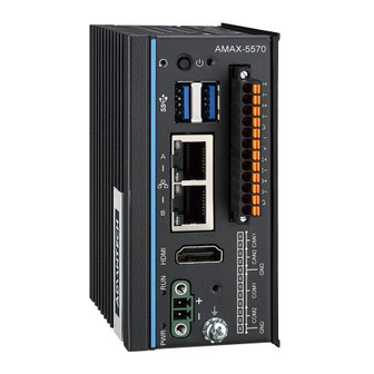
Page 22: External I/O Connector
External I/O Connector AMAX-5570 Base Unit Figure 2.5 Front Panel of AMAX-5570 Figure 2.6 Top View of AMAX-5570... -
Page 23: Power Connector
Manual- Appendix A.2 for pin assignments.) USB Connector AMAX-5570 features 2 x USB ports that comply with USB EHCI, 3 for Rev. 3.2 specifications. The USB connectors support plug-and-play and hot-swap- ping functionality for external devices. Additionally, this can be enabled/disabled in the BIOS menu. -
Page 24: Can Bus And Serial Port Connector
CAN bus and Serial Port Connector AMAX-5570 has 2 x CAN bus ports, 1 x COM RS232/422/485 port and 1 x COM RS- 485 port of terminal block type. They offer trans- mission speeds of 50 ~115.2 kbps. The default mode for COM1 is RS-485 Mode. Settings can be adjusted via an on- board switch (SW1). -
Page 25: Internal I/O Connectors And Switches
Internal I/O Connectors and Switches The following figure demonstrates the locations of internal connectors and switches on the AMAX-5570’s motherboard(MB) and daughterboard(DB01). Figure 2.7 Internal I/O Connectors & Switches in AMAX-5570 Note! *This power is from DC Power inputs AMAX-5570 User Manual... -
Page 26: Connector
There’s one Nano SIM Slot for supporting LTE function, labeled “SIM1” on board. In addition to install SIM card on “SIM1”, users are required to install a LTE Module on “M.2-B1” M.2 B Key to enable the functionality. AMAX-5570 User Manual... -
Page 27: Others
GPIO signal controls. Green indicates under programming. 2.4.2 Reset Buttons Press the “Reset” button to initiate a hardware reset. 2.4.3 Antenna Socket There are total 4 antenna sockets in AMAX-5570, see chapter 3.4 Wireless Module installation for assembly detail. AMAX-5570 User Manual... -
Page 28: Chapter 3 Initial Setup
Chapter Initial Setup This chapter explains how to Ini- tialize the AMAX-5570 ◼ Chassis Grounding ◼ Connecting Power ◼ Mounting instruction ◼ Installation instruction ◼ Extension Module Installation (Optional) ◼ Wireless Module Installation (Optional) ◼ BIOS Settings... -
Page 29: Chassis Grounding
Chassis Grounding The AMAX-5570 provides good EMI protection and a stable grounding base. There is an easy-to-connect chassis grounding point. Figure 3.1 Chassis Grounding Connection Diagram Earth terminal shall be used 16 AWG minimum size with green and yellow conductor to connector to earth. -
Page 30: Connecting Power
1 or UL 61010-1 or 61010-2-201 power supply only. This adapter is rated at 24Vdc, 3A and has a Tmax of 60 °C (140°F). If you need further assistance or information, please contact Advantech. Follow the following instructions: Insert the positive and negative wires into the V+ and V- contacts on the terminal block connector. - Page 31 3. After system turn to stand-by status so that operators could disconnect power input. Mounting Instruction AMAX-5570 come with DIN rail kit accessory, in general all system components can be securely installed onto a DIN-rail (35 mm) 1. Installed the system onto the DIN-rail.
- Page 32 The left side of system was main heat shrink position for CPU dissipation, strong recommended to keep more space for better nature air flow. Note! AMAX-5570 is designed with ruggedized fanless thermal solution. The heat generated from the motherboard dissipates thru the heat conduction thorough metal chassis.
- Page 33 Expansion Slots Installation (optional) AMAX-5570 supports the installation of AMAX-5000 series EtherCAT Slice IO modules on the right side. And provided local M.2 B key and mPCIe expansion capability. The installation demonstrate in the following steps. 3.5.1 Installing AMAX-5000 Slice IO module 1.
- Page 34 3. Follow the edge slot and install slice IO module until the module arrived the end point. 4. Push the hook back to original position to snap the rail.
- Page 35 3.5.2 Installing M.2 B key expansion module Remove 5 screws from device’s back cover.
- Page 36 Remove the provided screws from the board, and Insert the M.2 B key module(2242) on the expansion slot location. Secure it with the provided screw. Note! M.2 B key 3052 can also be installed by removing the 3052 bracket. Installed 5 screws back with device’s back cover.
- Page 37 3.5.3 Installing mPCIe expansion module Remove 5 screws from device’s back cover. Removed 2 screws from device’s top/bottom side, and disassemble the front cover.
- Page 38 Removed 3 screws between two layers and disassemble the IO board layer. Removed the screw on the stud of MB and installed mPCIe expansion module, then secure back the screw.
- Page 39 Assembly two boards together and then secure back 3 screws for chassis. Assembly front cover back and secure 2 screws for it.
- Page 40 Secure back cover with 5 screws...
-
Page 41: Wireless Module Installation (Optional)
Wireless Module Installation (Optional) AMAX-5570 supports to install Wireless module which come with antenna installation. There are total 4 antenna sockets and distributed into first layer and second layer. Follow the steps below for these antenna installation: 3.7.1 First Layer Antenna 1. - Page 42 3.7.2 Second Layer antenna 1. Followed previous steps to disassemble the back cover, then removed 2 screws at the second layer chassis which with 2 antenna holes, take off the antenna bracket. 2. Use screwdriver to drill though the holes on the bracket.
-
Page 43: Bios Setting
3. Install suitable SMA cable and antenna on the socket, then install back the antenna socket on the machine. Note! The SMA cable come with longer Heat-shrink tubing might get interference with the board edge. BIOS Setting With the BIOS Setup program, you can modify BIOS settings and control the special features of your computer. -
Page 44: System Settings/Pin Assignments
Appendix System Settings/Pin Assignments... -
Page 45: Power Connector (Dcin1)
1000BASE-T: In MDI and in MDI-X configuration, MDI2- MDI[2]+/- corresponds to BI_DC+/- and MDI[3]+/ - MDI3+ corresponds to BI_DD+/-. ◼ 100BASE-TX: Unused. MDI3- ◼ 10BASE-T: Unused. Right LED Left LED 10Link 100 Link 1000 Link Active Orange Green Green AMAX-5570 User Manual... -
Page 46: Usb Connector (Usb1)
Table A.4: USB 3.0 Connector Pin Assignments Signal Name Description VBUS Power USB 2.0 differential pair Ground for power return StdA_SSRX- SuperSpeed receiver differential pair StdA_SSRX+ GND_DRIAN Ground for signal return StdA_SSTX- SuperSpeed transmitter differential pair StdA_SSTX+ AMAX-5570 User Manual... - Page 47 TMDS Data2 Shield TMDS Data2- TMDS Data1+ TMDS Data1 Shield TMDS Data1- TMDS Data0+ TMDS Data0 Shield TMDS Data0- TMDS Clock+ TMDS Clock Shield TMDS Clock- Reserved DDC/CEC/HEC Ground +5 V Power (max 50 mA) Hot Plug Detect AMAX-5570 User Manual...
-
Page 48: M.2 Connector
Mechanical notch B Mechanical notch B Mechanical notch B Mechanical notch B Mechanical notch B Mechanical notch B WAKE_ON_WAN# M2_LTE_W2_DISABLE_N USB_Z_SSRX1- M2_SIM1_RESET USB_Z_SSRX1+ M2_SIM1_CLK M2_SIM1_DATA USB_C_SSTX1- M2_SIM1_PWR USB_C_SSTX1+ M2_SIM2_DET SATA1_RX+ SATA1_RX- SATA1_C_TX- SATA1_C_TX+ M2_SIM1_DET LTE_RST#_P67 +V3.3_M2 +V3.3_M2 +V3.3_M2 AMAX-5570 User Manual... -
Page 49: Mpcie Connector (Mini1)
Connector (CN3) Table A.9: mPCIe Connector Pin Assignments Signal Name Signal Name PCIE_WAKE# +V3.3_MINI +V1.5 PCIEX1_CLKREQ0# CLK100M_PCIEX1_D0- CLK100M_PCIEX1_D0+ WIFI_DISABLE# MINI_PLTRST# SATA0_RX+ +V3.3_MINI SATA0_RX- +V1.5 SATA0_TX- SATA0_TX+ USB_Z_P8- USB_Z_P8+ +V3.3_MINI +V3.3_MINI MPCIE_PWRSEL +V1.5 MSATA#_z_PCIE_SEL +V3.3_MINI AMAX-5570 User Manual... - Page 50 M.2 B key PIN Configuration (SW1) When M.2 B key installed Wireless module, these modules got individual PIN configuration which AMAX-5570 provided for configuring. Pin1(M.2_pin20) Pin2(M.2_pin22) High(1.8V) Pin3(M.2_pin38) Pin4(M.2_Pin68) Pin5 Pin6 COM1 RS232/422/485 mode & COM1,COM2 Terminal Setting(SW2) The default setting for the COM1 port is RS-232. This can be switched to RS-422 or RS- 485 mode with PIN1&PIN2 of SW2.
-
Page 51: At/Atx Setting (Pson1)
AT/ATX Setting (SW4) SW4 using jumper for setting AT/ATX mode. The default setting is AT mode. See the follow table for jumper installation for mode. Default Description Instruction ATX Mode Closed 2-3 AT Mode Closed 1-2 (Default) AMAX-5570 User Manual... - Page 52 A.12 Riser Connector (BTB1) Table A.11: Expansion Board to Board Connector Pin Assignments AMAX-5570 User Manual...
-
Page 53: Tpm 2.0 Bios Setting
A.13 TPM 2.0 BIOS Setting The AMAX-5570 systems support TPM 2.0 functionality. This can be enabled or dis- abled in the BIOS menu by following the instructions provided below: Power on the AMAX-5570 system and press “Delete” to enter the BIOS configura- tion menu. - Page 54 Real-time feature(CODESYS Support) The AMAX-5570 systems d e f a u l t c o m e w i t h “ C O D E S Y S E n a b l e d ” s o t h a t support real-time application which followed CODESYS real time engine(RTE) recommendation, which would keep CPU in more stable way to make sure accurate timing for control application task.
- Page 55 A.15 Ctrl Driver GPIO Scheme For Linux environment, we recommend user to enable this item to make sure all drivers worked properly with the OS. Disabled this item would cause Linux OS operation slow or shutdown error. AMAX-5570 User Manual...
- Page 56 No part of this publication may be reproduced in any form or by any means, electronic, photocopying, recording or otherwise, without prior written permis- sion from the publisher. All brand and product names are trademarks or registered trademarks of their respective companies. © Advantech Co., Ltd. 2020 AMAX-5570 User Manual...
Need help?
Do you have a question about the AMAX-5570 and is the answer not in the manual?
Questions and answers