Table of Contents
Advertisement
Quick Links
Advertisement
Table of Contents

Related Manuals for Advantech ARK-3440 Series


Summary of Contents for Advantech ARK-3440 Series
- Page 1 User Manual ARK-3440 Fanless Embedded Box PC...
- Page 2 The documentation and the software included with this product are copyright © 2012 by Advantech Co., Ltd. All rights are reserved. Advantech Co., Ltd. reserves the right to make improvements in the products described in this manual at any time without notice.
- Page 3 Because of Advantech’s high quality-control standards and rigorous testing, most of our customers never need to use our repair service. If an Advantech product is defec- tive, it will be repaired or replaced at no charge during the warranty period. For out- of-warranty repairs, you will be billed according to the cost of replacement materials, service time and freight.
- Page 4 Technical Support and Assistance Visit the Advantech web site at www.advantech.com/support where you can find the latest information about the product. Contact your distributor, sales representative, or Advantech's customer service center for technical support if you need additional assistance. Please have the following information ready before you call: –...
- Page 5 Safety Instructions Read these safety instructions carefully. Keep this User Manual for later reference. Disconnect this equipment from any AC outlet before cleaning. Use a damp cloth. Do not use liquid or spray detergents for cleaning. For plug-in equipment, the power outlet socket must be located near the equip- ment and must be easily accessible.
- Page 6 Packing List Before installation, please ensure the following items have been shipped: 1 x ARK-3440 Unit 1 x Rubber foot kit 2 x Desk/Wall mount plate 1 x 4-pin Phoenix DC power connector 1 x DVI-I to VGA adaptor ...
-
Page 7: Table Of Contents
Contents Chapter General Introduction ......1 Introduction ....................2 Product Features..................2 1.2.1 General ..................2 1.2.2 Display ..................2 1.2.3 Power Consumption..............2 Hardware Specifications ................3 Mechanical Specifications................. 4 1.4.1 Dimensions ................... 4 Figure 1.1 ARK-3440 Mechanical Dimensions Drawing....4 1.4.2 Weight................... - Page 8 Figure 2.12HDMI receptacle connector........13 Table 2.5: HDMI receptacle connector pin assignments... 13 2.3.4 Ethernet Connector (LAN) ............13 Figure 2.13Ethernet connector ........... 13 Table 2.6: RJ-45 Connector pin assignments ......13 2.3.5 LVDS Connector (Optional) ............14 Figure 2.14LVDS Connector (optional) ........14 Table 2.7: LVDS Connector Pin Assignment ......
- Page 9 Appendix B Display Application ......45 Introduction ..................... 46 Figure B.1 BIOS VGA setting............. 46 LVDS....................... 46 Dual Display .................... 46 B.3.1 Display modes ................47 Display Resolution Setting ..............47 Appendix C Application Notes ......49 RS-485 Supports Auto Flow Control ............50 Figure C.1 BIOS COM port setting..........
- Page 10 ARK-3440 User Manual...
-
Page 11: Chapter 1 General Introduction
Chapter General Introduction This chapter gives background information on the ARK-3440 series. -
Page 12: Introduction
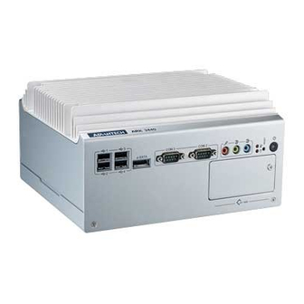
Introduction ARK-3440 Box IPC is an ideal, application-ready, system platform solution. All elec- tronics are protected in a compact sealed aluminum case for easy embedding in the customer’s own housing, or as a stand-alone where space is limited and the environ- ment is harsh. -
Page 13: Hardware Specifications
Hardware Specifications ® CPU: Intel Core™ i7-610E 2.53 GHz / Core™ i5-520E 2.4GHz / CoreTM i3- 330E 2.13 GHz ® System Chipset: Intel QM57 BIOS: AMI™ 64 bit, SPI System Memory: 2 x 204-pin-pin SODIMM socket, Support DDR3 1066 MHz, up to 4 GB ... -
Page 14: Mechanical Specifications
Mechanical Specifications 1.4.1 Dimensions Units: mm Figure 1.1 ARK-3440 Mechanical Dimensions Drawing 1.4.2 Weight 4.0 kg (8.8lb) Power Requirements 1.5.1 System power Minimum power input: DC 9 V ~ 34 V 9.0 A ~ 2.4 A 1.5.2 RTC battery 3 V / 195 mAH BR2032 ARK-3440 User Manual... -
Page 15: Environmental Specifications
Environmental Specifications 1.6.1 Operating temperature With Industrial Grade CompactFlash disk: 0 ~ 50° C, with air flow With 2.5" consumer grade HDD on internal HDD bay: 0 ~ 45° C, with air flow 1.6.2 Relative Humidity 95% @ 40° C (non-condensing) 1.6.3 Storage temperature -40 ~ 85°... - Page 16 ARK-3440 User Manual...
-
Page 17: Chapter 2 Hardware Installation
Chapter Hardware installation This chapter introduces external IO and the installation of ARK-3440 Hardware. -
Page 18: I/O Locations
I/O Locations LE D R E S E T L IN -O U T U S B 1 U S B 3 U S B 2 U S B 4 eS A T A C O M 3 C O M 2 M IC L IN -IN O N /O F F... -
Page 19: Front Panel Controls, Indicators, & Connectors
Front Panel Controls, Indicators, & Connectors 2.2.1 Power ON/OFF Button ARK-3440 has a Power On/Off button with LED indicators on the front side that show On status (Green LED) and Off/Suspend status (Orange LED). The Power button supports dual functions: Soft Power -On/Off (Instant off or Delay 4 Seconds then off), and Suspend. -
Page 20: Com Connector
2.2.5 COM Connector ARK-3440 provides 6 D-sub 9-pin connectors that are serial communication interface ports. The COM1 on the rear panel supports RS-232/422/485 mode by BIOS selec- tion; COM2 and 3 on the front panel and COM5 and 6 on the internal header only. The COM1 and COM4 default settings are RS-232;... -
Page 21: Usb Connector
2.2.7 USB Connector ARK-3440 provides six USB connectors that give complete Plug & Play and hot swapping for up to 127 external devices. The USB interface complies with USB UHCI, Rev. 2.0 compliant. The USB interface can be disabled in the system BIOS setup. -
Page 22: Digital Visual Interface Connector (Dvi-I)
2.3.2 Digital Visual Interface Connector (DVI-I) The ARK-3440 offers an integrated D-sub 24-pin female DVI-I Digital Visual Interface connector; it carries integrated analog and digital video signals. This supports high- speed, high-resolution digital displays and traditional analog displays. Figure 2.11 DVI-I Connector Table 2.4: DVI-I Connector pin assignments Signal Name Signal Name... -
Page 23: Hdmi Connector
2.3.3 HDMI Connector An integrated, 19-pin receptacle connector HDMI Type A Interface is provided. The HDMI link supports resolutions up to 1920x1200@60Hz. Figure 2.12 HDMI receptacle connector Table 2.5: HDMI receptacle connector pin assignments Signal Name Signal Name TMDS Data 2+ TMDS Data 2 shield TMDS Data 2- TMDS Data 1+... -
Page 24: Lvds Connector (Optional)
2.3.5 LVDS Connector (Optional) The ARK-3440 supports a D-Sub 26-pin connector that carries an LVDS signal out- put, and can direct-connect to LVDS LCD display via external cable. The system also provides jumper JP5 on the internal motherboard for selecting the LCD signal power of 5V or 3.3V;... -
Page 25: Lcd Backlight On/Off Control Connector (Optional)
2.3.6 LCD Backlight On/Off control Connector (Optional) The ARK-3440 supports a D-sub 9-pin connector which provides BKLTEN signal as well as +12 V, +5 V and Ground Pin signals that allow the user to connect these sig- nals to an LCD inverter to implement the LCD On/Off control. ... -
Page 26: Lpt Connector (Optional)
2.3.7 LPT Connector (Optional) The ARK-3440 supports one D-sub 25-pin female connector, which can serve as a printer or other communications interface port. Pin assignments are as follows. Figure 2.16 LPT Connector (optional) Table 2.9: LPT Connector Pin Assignment Signal Name Signal name STROBE ERROR... -
Page 27: Memory Installation
Memory Installation Remove the top screws and top cover. Remove two screws and memory heatspreader. Insert the memory module into the SODIMM socket. If only one memory module is being installed, always install it into CN12. Reinstall heatspreader and top cover. Figure 2.17 Memory Installation ARK-3440 User Manual... -
Page 28: Compact Flash Installation
Compact Flash Installation Open the front CF/HDD door by loosening the door screw. Insert the CF card into the CF socket, then reassemble. Figure 2.18 CF Card Installation HDD Installation 2.6.1 Internal fixed HDD installation Remove the bottom cover by unscrewing the 4 screws Install the 2.5”... -
Page 29: Removable 2.5" Storage Device Installation
2.6.2 Removable 2.5" Storage Device Installation It is recommended to use 2.5" SATA solid state device on the removable bay. Open the front CF/HDD door by loosening the door screw. Attach the 2.5” SATA storage device to the loader with 4 HDD mounting screws Slide HDD loader along the rails to the end and fix the lever screw. -
Page 30: Mini Pcie Installation
Mini PCIe Installation Open the bottom cover and remove the riser card module. (Refer Chapter 2.4) Insert the Mini PCIe card into the Mini PCIe socket and latch into place. Figure 2.22 Mini PCI Card Installation Antenna Installation Remove the top heatsink by loosening the four screws. (See Section 2.4) Pass the internal antenna cable jack through the antenna hole in the rear panel and fix it in place by tightening the matching nut. -
Page 31: Optional Cable Installation
2.10 Optional Cable Installation Open the bottom cover and follow the illustration and table below for optional cable installations and connections. Figure 2.24 Optional Cable Installation Rear Panel Connector Internal Connector LVDS power cable (P/N:1700009396)* LVDS cable (P/N:1700009398) COM5 cable (P/N:1700008871) COM6 cable (P/N:1700008871) LPT cable (P/N:1700018187) ARK-3440 User Manual... -
Page 32: Cpu Thermal Grease Pad
(JP5) needs to be configured. 2.11 CPU Thermal Grease Pad CPU thermal grease pad is one of the key components of ARK-3440 thermal design. Always use the grease pad provided by Advantech. The P/N of the grease pad is : Part Number Description 1990020828N001 Thermal-Pad D27*0.25 K=3 TP HW-PCM45Fφ27*0.25... -
Page 33: Bios Settings
Chapter BIOS settings This chapter introduces how to set BIOS configurations. -
Page 34: Bios Introduction
BIOS Introduction Advantech provides a current version of the full-featured AMI BIOS that has been integrated into many motherboards for over a decade. With the AMI BIOS Setup pro- gram, users can modify BIOS settings and control various system features. This chapter describes the basic navigation of the ARK-3440 BIOS setup screens. -
Page 35: Main Setup
3.2.1 Main Setup When users first enter the BIOS Setup Utility, they enter the Main setup screen. Users can always return to the Main setup screen by selecting the Main tab. There are two Main Setup options. They are described in this section. The Main BIOS Setup screen is shown below. -
Page 36: Advanced Bios Features Setup
Advanced BIOS Features Setup Select the Advanced tab from the ARK-3440 setup screen to enter the Advanced BIOS Setup screen. Users can select any item in the left frame of the screen, such as PCI Configuration, to go to the sub menu for that item. Users can display an Advanced BIOS Setup option by highlighting it using the <Arrow>... - Page 37 – PCI Common Settings PCI Latency Timer: Value to be programmed into PCI Latency Timer Register. 32 PCI Bus Clocks [Default] 64 PCI Bus Clocks 96 PCI Bus Clocks 128 PCI Bus Clocks 160 PCI Bus Clocks 192 PCI Bus Clocks 224 PCI Bus Clocks 248 PCI Bus Clocks –...
- Page 38 – Hyper-threading: Enabled for Windows XP and Linux (OS optimized for Hyper-Threading Technology) and Disabled for other OS (OS not optimized for Hyper-Threading Technology). When Disabled only one thread per enabled core is enabled. Disabled Enabled [Default] – Active Processor Cores: Number of cores to enable in each processor pack- age.
- Page 39 Disable Energy Efficient Custom [Default] – TDC Limit: Turbo-XE Mode Processor TDC Limit in 1/8 A granularity. 0 means using the factory-configured value. – TDP Limit: Turbo-XE Mode Processor TDP Limit in 1/8 W granularity. 0 means using the factory-configured value. ...
- Page 40 2048x1536 LVDS – Panel Scaling: Select the LCD panel scaling option used by the Internal Graphics Device. Auto [Default] Force Scaling Maintain Aspect Ratio – Backlight Control: Back Light Control Setting. PWM Inverted [Default] PWM Normal GMBus Inverted GMBus Normal –...
- Page 41 – TDT: Enable/Disable TDT in BIOS for testing only. Disabled [Default] Enabled Intel TXT(LT) Configuration: Intel Trusted Execution Technology Intel TXT(LT) Support Disabled [Default] Enabled USB Configuration: USB Configuration Parameters – Legacy USB Support: Enables Legacy USB support. AUTO option disables legacy support if no USB devices are connected.
- Page 42 IO=278h; IRQ=3,4,5,6,7,10,11,12; IO=3BCh; IRQ=3,4,5,6,7,10,11,12; IO=378h; IO=278h; IO=3BCh; – Device Mode: Change the Printer Port mode. STD Printer Mode [Default] SPP Mode EPP-1.9 and SPP Mode EPP-1.7 and SPP Mode ECP Mode ECP and EPP 1.9 Mode ECP and EPP 1.7 Mode ...
-
Page 43: Chipset Bios Feature Setup
Chipset BIOS Feature Setup Select the Chipset tab from the ARK-3440 setup screen to enter the Chipset BIOS Setup screen. Users can select any item in the left frame of the screen, such as PCI Configuration, to go to the sub menu for that item. Users can display a Chipset BIOS Setup option by highlighting it using the <Arrow>... - Page 44 – PCI Express Compliance Mode: PCI Express Compliance Testing Mode. Disabled [Default] Enabled – PCI Express Port: PCI Express. Disabled Enabled Auto [Default] – IGD Memory: IGD Share Memory Size. Disabled 32M [Default] 128M – PAVP Mode: Select PAVP Mode used by Internal Graphics Device. Disabled [Default] Enabled –...
- Page 45 – Azalia internal HDMI codec: Enable/Disable internal HDMI codec for Azalia. Disabled [Default] Enabled – High Precision Timer: Enable or Disable the High Precision Event Timer. Disabled Enabled [Default] – PCI Express Ports Configuration: PCI Express Ports Configuration – PCI Express Port 1: Enable or Disable the PCI Express Ports in the Chipset. Disabled Enabled Auto [Default]...
- Page 46 – EHCI Controller 2: Enable / Disable USB 2.0 (EHCI) Support. Disabled Enabled [Default] – RMH Support: Enable / Disable RMH Support; AUTO: Only Enable RMH support on Ibex Peak B0 Stepping. Disabled Enabled Auto [Default] – USB Port 0: Enable / Disable USB Port 0. Disabled Enabled [Default] –...
-
Page 47: Boot Bios Feature Setup
Boot BIOS Feature Setup Select the BOOT tab from the setup screen to enter the BOOT BIOS Setup screen. Users can select any item in the left frame of the screen, such as PCI Configuration, to go to the sub menu for that item. Users can display a BOOT BIOS Setup option by highlighting it using the <Arrow>... -
Page 48: Security Bios Feature Setup
Option ROM Messages: Set display mode for Option ROM. Force BIOS [Default] Keep Current Interrupt 19 Capture: Enabled: Allows Option ROMs to trap Int 19. Disabled [Default] Enabled Boot Option Priorities: Sets the system boot order. Hard Drive BBS Priorities:Sets the order of the legacy devices in this group. -
Page 49: Save & Exit Bios Feature Setup
Save & Exit BIOS Feature Setup Select the BOOT tab from the ARK-3440 setup screen to enter the save BIOS Setup screen. Users can select any item in the left frame of the screen. Users can display a save BIOS Setup option by highlighting it using the <Arrow> keys. All save BIOS Setup options are described in this section. - Page 50 Save Changes: Save Changes done so far to any of the setup options. Save configuration? Yes [Default] Discard Changes: Discard Changes done so far to any of the setup options. Load Previous Values? Yes [Default] Restore Defaults: Restore/Load Defaults values for all the setup options. Load Optimized Defaults? Yes [Default] ...
-
Page 51: Appendix A Function Settings
Appendix Function Settings... -
Page 52: Function Setting
Function Setting Figure A.1 Top View Figure A.2 Bottom View ARK-3440 User Manual... - Page 53 Table A.1: ATX / AT Mode switch ATX / AT Mode switch Footprint 3x1 Pin Setting Function (1-2) (2-3) ATX Mode (default) Table A.2: PCI Express mini card version select JP2 / JP6 mini PCI Express mini card version select Footprint 3x1 Pin Setting...
- Page 54 ARK-3440 User Manual...
-
Page 55: Appendix B Display Application
Appendix Display Application... -
Page 56: Introduction
Introduction The ARK-3440 has an onboard Intel® QM57 chipset for its PCIE controller. It sup- ports LVDS DVI and HDMI displays and conventional analog CRT monitors. The VGA controller can drive CRT displays with resolutions up to 2048 x 1536 @ 60Hz, support 48 bits LVDS display mode up to UXGA panel resolution with frequency range from 25-MHz to 112-MHz. -
Page 57: Display Modes
B.3.1 Display modes Clone mode Initially on PCs, the multiple output interface was designed to display the same image on all output interfaces (sometimes referred to as mirroring or cloning). This reflected the fact that these video cards were originally used in presentations where the user typically had his or her face to the audience with a duplicate of the projected image available to the presenter. - Page 58 ARK-3440 User Manual...
-
Page 59: Appendix C Application Notes
Appendix Application Notes... -
Page 60: Rs-485 Supports Auto Flow Control
RS-485 Supports Auto Flow Control ARK-3440 COM1 port connector located on the rear panel and COM4 can be config- ured to operate in RS-232, RS-422 or RS-485 mode by adjusting the "Onboard Serial port 3 Mode" & "Onboard Serial port 4 Mode" of "Integrated Peripherals" in the BIOS. Refer to Chapter 3 "BIOS Operation"... -
Page 61: Software Flow Control
C.1.2 Software Flow Control Both software and hardware flow control need software to perform the handshaking task. This makes the term software flow control somewhat misleading. What is meant is that with hardware flow control, additional lines are present in the communication cable which signal handshaking conditions. -
Page 62: How To Implement
One is, where the RTS of each side is connected with the CTS side of the other. In that way, the communication protocol differs somewhat from the original one. The RTS output of computer A signals computer B that A is capable of receiving informa- tion, rather than a request for sending information as in the original configuration. -
Page 63: System Requirements - Pc Compatible
C.2.2 System Requirements - PC Compatible Wake on LAN (WoL) support is implemented on the motherboard of a computer. Most modern motherboards with an embedded Ethernet controller support WoL with- out the need for an external cable. Older motherboards must have a WAKEUP-LINK header onboard and connected to the network card via a special 3-pin cable;... - Page 64 ARK-3440 User Manual...
- Page 65 No part of this publication may be reproduced in any form or by any means, electronic, photocopying, recording or otherwise, without prior written permis- sion of the publisher. All brand and product names are trademarks or registered trademarks of their respective companies. © Advantech Co., Ltd. 2012...
- Page 66 ARK-3440 User Manual...
Need help?
Do you have a question about the ARK-3440 Series and is the answer not in the manual?
Questions and answers