Table of Contents
Advertisement
Quick Links
Advertisement
Table of Contents

Subscribe to Our Youtube Channel
Related Manuals for Advantech ARK-3403


Summary of Contents for Advantech ARK-3403
- Page 1 User Manual ARK-3403...
- Page 2 A product returned without proof of the purchase date is not eligible for warranty service. Write the RMA number visibly on the outside of the package and ship it prepaid to your dealer. Part No. 2006340301 Edition 2 Printed in China September 2010 ARK-3403 User Manual...
- Page 3 Association, work sites are classified into different classes, divisions and groups, based on hazard considerations. This equipment is compliant with the speci- fications of Class I, Division 2, Groups A, B, C and D indoor hazards. ARK-3403 User Manual...
- Page 4 Discard used batteries according to the manufacturer's instructions. Note! Notes provide optional additional information. Document Feedback To assist us in making improvements to this manual, we would welcome comments and constructive criticism. Please send all such - in writing to ARK-3403 User Manual...
- Page 5 The sound pressure level at the operator's position according to IEC 704-1:1982 is no more than 70 dB (A). DISCLAIMER: This set of instructions is given according to IEC 704-1. disclaims all responsibility for the accuracy of any statements contained herein. ARK-3403 User Manual...
- Page 6 Don't touch any components on the CPU card or other cards while the PC is on. Disconnect power before making any configuration changes. The sudden rush of power as you connect a jumper or install a card may damage sensitive elec- tronic components. ARK-3403 User Manual...
-
Page 7: Table Of Contents
Figure 2.9 USB connector ............9 Table 2.2: USB Connector............9 2.2.8 Compact Flash Card ..............9 ARK-3403 rear side external I/O connectors ..........9 2.3.1 Power Input Connector ..............9 Figure 2.10Power Input Connector..........9 Table 2.3: Power connector pin assignments......9 2.3.2... - Page 8 Figure 3.10Chipset ACPI Configuration ........29 3.4.6 AHCI Configuration..............30 Figure 3.11Advanced ACPI Configuration........30 3.4.7 APM Configuration..............30 Figure 3.12APM Configuration ........... 30 3.4.8 Event Log Configuration ............. 31 Figure 3.13South Bridge ACPI Configuration......31 3.4.9 MPS Configuration..............32 ARK-3403 User Manual viii...
- Page 9 Table A.3: COM1 / COM2 RS232/422/485 select ..... 57 Appendix B Application Notes ......59 WOL Setting.................... 60 B.1.1 Introduction ................. 60 B.1.2 System requirements - PC Compatible........60 B.1.3 How it works................61 B.1.4 Magic Packet ................61 ARK-3403 User Manual...
- Page 10 ARK-3403 User Manual...
-
Page 11: Chapter 1 General Introduction
Chapter General Introduction This chapter gives background Information on ARK-3403 series. -
Page 12: Introduction
The ARK-3403 answers this demand by offering 6 x USB 2.0 ports, 2 x Giga LAN port, audio function, 4 x COM ports and 2 PCI expansion slots; packed into a small rugged unit and powered by an Intel Atom D510 processor. -
Page 13: Hardware Specifications
1 Slot PCI and 1 Slot PCIe X 1 – 2 Slots PCIe x 1 (Optional) – 2 Slots PCI (Optional) – 2 x Mini PCIe Mechanical Specifications 1.4.1 Dimensions Unit: mm Figure 1.1 ARK-3403 Mechanical dimension drawing ARK-3403 User Manual... -
Page 14: Weight
Shock during operation With CompactFlash Disk: 50 G, IEC60068-2-27, half sine, 11 ms duration With 2.5-inch hard disk: 20 G, IEC60068-2-27, half sine, 11 ms duration 1.6.6 CE/FCC Class A, CCC, BSMI 1.6.7 Safety UL, CCC, BSMI ARK-3403 User Manual... -
Page 15: Chapter 2 Hardware Installation
Chapter Hardware Installation This chapter introduces external IO and the installation of ARK- 3403 Hardware. -
Page 16: Ark-3403 I/O Indication
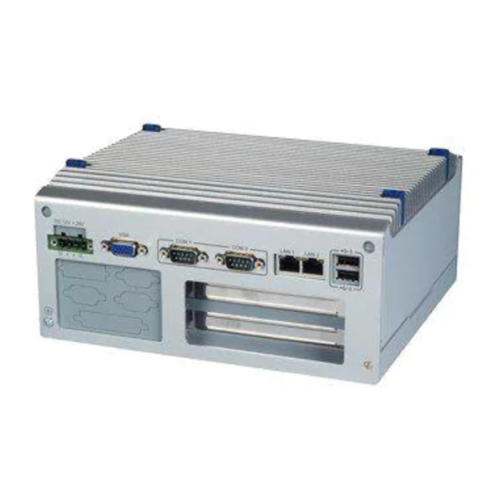
ARK-3403 I/O indication Figure 2.1 ARK-3403 Front view Figure 2.2 ARK-3403 Rear view ARK-3403 User Manual... -
Page 17: Ark-3403 Front Side External I/O Connectors
2.2.1 Power ON/OFF Button ARK-3403 comes with a Power On/Off button with LED indicators on the front side to show its On status (Green LED) and Off/Suspend status (Orange LED), that support dual function of Soft Power -On/Off (Instant off or Delay 4 Second), and Suspend. -
Page 18: Com Connector
Note: NC represents “No Connection”. 2.2.6 e-SATA Connector ARK-3403 has a 7 pin external connector for e-SATA device. That is fully compliant with SATA I/SATA II standards, its can be access with external SATA I/SATA II device then up to 300MB/sec. -
Page 19: Usb Connector
Signal Name USB data- USB data+ 2.2.8 Compact Flash Card ARK-3403 is equipped with an external CF card. You can find the installation in Chapter 2.5. ARK-3403 rear side external I/O connectors 2.3.1 Power Input Connector ARK-3403 comes with a two pins header that carries 12~24 VDC external power input. -
Page 20: Vga Connector
2.3.2 VGA Connector The ARK-3403 offers a high resolution VGA interface via D-Sub 15 pin connector to support a VGA monitor. It supports VGA and VESA, the display output resolution up to 2048 * 1536 @ 60 Hz. Figure 2.11 VGA connector Table 2.4: VGA Connector pin assignments... -
Page 21: Lvds Connector (Optional)
2.3.4 LVDS Connector (Optional) The ARK-3403 comes with a D-Sub 26-pin connector that carries LVDS signal out- put, and can direct connect to LVDS LCD Display via external cable. The system also provides power of 3.3V. Figure 2.13 LVDS connector Table 2.6: CN35 LVDS Connector Pin Assignment... -
Page 22: Lcd Backlight On/Off Control Connector (Optional)
2.3.5 LCD backlight On/Off control Connector (Optional) The ARK-3403 comes with a D-Sub 9-pin connector which provides BKLTEN signal as well as +12V, +5V and Ground Pin signals that allow the user to connect these signals to LCD Inverter to implement the LCD On/Off control. -
Page 23: Lpt Connector (Optional)
2.3.6 LPT Connector (Optional) The ARK-3403 provides one D-sub 25-pin female connector, which offers printers or other communication interface port. If you want to use LPT port, you can find the Pin assignment as following. Figure 2.15 LPT connector Table 2.8: CN29 LPT Connector Pin Assignment... -
Page 24: Dio Connector (Optional)
2.3.7 DIO Connector (Optional) The ARK-3403 provides one D-sub 25-pin male connector, which offers Digital I/O communication interface port. If you want to use DIO port, you can find the Pin assignment as following. Figure 2.16 DIO connector Table 2.9: CN32 DIO Connector Pin Assignment... -
Page 25: Memory Installation
Memory Installation Remove top screws and heatsink. Remove the heatspreader by unscrewing the 5 screws. Insert the memory module into the SODIMM socket. Reverse steps to reassemble. Figure 2.17 Memory installation ARK-3403 User Manual... -
Page 26: Compact Flash Installation
Internal fixed HDD installation Remove 4 retaining screws and the bottom cover. Install the 2.5-inch SATA HDD with 4 HDD screws. Connect the SATA signal cable and power cable. Reverse steps to reassemble. Figure 2.19 Internal fixed HDD installation ARK-3403 User Manual... -
Page 27: Removable Hdd Installation
Loosen door screw and open front CF/HDD door. Attach the 2.5-inch SATA HDD on the loader with 4 HDD screws. Slide in HDD loader along the rails to the end and fix with lever screw. Close door and fasten. Figure 2.20 Removable HDD installation ARK-3403 User Manual... -
Page 28: Pci Card Installation
Remove the riser card module. Insert the PCI extension card into the PCI slot of the riser card module. Reattach the riser card module. Replace bottom cover and secure with the 4 screws. Figure 2.21 Removable PCI Installation ARK-3403 User Manual... -
Page 29: Mini Pcie Installation
Remove top screws and heatsink. (Refer Chapter 2.1) Pass the internal antenna cable jack through the antenna hole on the rear panel and fix it in place with the matching nut. Attache the external antenna. Reattach heatsink. Figure 2.23 Antenna installation ARK-3403 User Manual... - Page 30 ARK-3403 User Manual...
-
Page 31: Chapter 3 Bios Settings
Chapter BIOS Settings This chapter introduces how to set BIOS configuration data. -
Page 32: Bios Introduction
With the AMI BIOS Setup program, users can modify BIOS settings and control various system features. This chapter describes the basic navigation of the ARK-3403 BIOS setup screens. Figure 3.1 Setup program initial screen AMI's BIOS ROM has a built-in Setup program that allows users to modify the basic system configuration. -
Page 33: Main Setup
Date using the <Arrow> keys. Enter new values through the keyboard. Press the <Tab> key or the <Arrow> keys to move between fields. The date must be entered in MM/DD/YY format. The time must be entered in HH:MM:SS format. ARK-3403 User Manual... -
Page 34: Advanced Bios Features Setup
Advanced BIOS Features Setup Select the Advanced tab from the ARK-3403 setup screen to enter the Advanced BIOS Setup screen. You can select any of the items in the left frame of the screen, such as CPU Configuration, to go to the sub menu for that item. You can display an Advanced BIOS Setup option by highlighting it using the <Arrow>... -
Page 35: Ide Configuration
Hard Disk Write Protect Disable/Enable device write protection. This will be effective only if device is accessed through BIOS. IDE Detect Time Out (Sec) This item allows you to select the time out value for detecting ATA/ATAPI device(s). ARK-3403 User Manual... -
Page 36: Super Io Configuration
This item allows you to select parallel port mode. Parallel Port IRQ This item allows you to select parallel port IRQ. LPT/FDD Switch This function will switch LPT port to FDD mode. WatchDog Function WatchDog function support (Seconds/Minutes). ARK-3403 User Manual... -
Page 37: Hardware Health Configuration
Figure 3.6 Hardware Health Configuration H/W Health Function This item allows you to enable or disable H/W monitoring. Temperature & Voltage show CPU/System Temperature Vcore / +3.3Vin / +5Vin / +12Vin / VBAT 3.4.5 ACPI Configuration Figure 3.7 ACPI Settings ARK-3403 User Manual... -
Page 38: Figure 3.8 General Acpi Configuration
This item allows you to invoke VA BIOS POST on S3/STR resume. 3.4.5.2 Advanced ACPI Configuration Figure 3.9 Advanced ACPI Configuration ACPI Version Features This item allows you to enable RSDP pointers to 64-bit fixed system description tables. ARK-3403 User Manual... -
Page 39: Figure 3.10Chipset Acpi Configuration
Allows you to configure Intel’s Energy Lake power management technology. APIC ACPI SCI IRQ Enable/Disable APIC ACPI SCI IRQ. USB Device Wakeup From S3/S4 Enable/Disable USB Device Wakeup from S3/S4. High Performance Event Timer Enable / Disable High performance Event timer. ARK-3403 User Manual... -
Page 40: Ahci Configuration
Figure 3.11 Advanced ACPI Configuration AHCI Ports0 / Port1 / Port2 While entering setup, BIOS auto detects the presence of IDE devices. This dis- plays the status of auto detected IDE devices. 3.4.7 APM Configuration Figure 3.12 APM Configuration ARK-3403 User Manual... -
Page 41: Event Log Configuration
Enable / Disable RI to generate a wake event. Resume On PME# Enable / Disable PME to generate a wake event. Resume On RTC Alarm Enable / Disable RTC to generate a wake event. 3.4.8 Event Log Configuration Figure 3.13 South Bridge ACPI Configuration ARK-3403 User Manual... -
Page 42: Mps Configuration
Mark all events as read Mark all unread events as read. Clear Event Log Discard all events in the event Log. 3.4.9 MPS Configuration Figure 3.14 South Bridge ACPI Configuration MPS Revision This item allows you to select MPS reversion. ARK-3403 User Manual... -
Page 43: Smbios Configuration
3.4.10 Smbios Configuration Figure 3.15 South Bridge ACPI Configuration SMBIOS SMI Support SMBIOS SMI wrapper support for PnP function 50h-54h. 3.4.11 USB Configuration Figure 3.16 South Bridge ACPI Configuration ARK-3403 User Manual... -
Page 44: Figure 3.17Usb Mass Storage Device Configuration
If Auto, USB devices less than 530 MB will be emulated as Floppy and larger as hard drive. Force FDD option can be used to force a FDD formatted drive to boot as FDD (E.G., a ZIP drive). ARK-3403 User Manual... -
Page 45: Advanced Pci / Pnp Settings
Advanced PCI / PnP Settings Select the PCI/PnP tab from the ARK-3403 setup screen to enter the Plug and Play BIOS Setup screen. You can display a Plug and Play BIOS Setup option by highlight- ing it using the <Arrow> keys. All Plug and Play BIOS Setup options are described in this section. -
Page 46: Boot Settings
When set to Reserved, the specified DMA will be reserved for legacy ISA devices. Reserved Memory Size Use to set size of reserved memory block for legacy ISA device. Boot Settings Figure 3.19 Boot Setup Utility 3.6.1 Boot Settings Configuration Figure 3.20 Boot Setting Configuration ARK-3403 User Manual... -
Page 47: Security Setup
Security Setup Figure 3.21 Password Configuration Select Security Setup from the ARK-3403 Setup main BIOS setup menu. All Security Setup options, such as password protection and virus protection, are described in this section. To access the sub menu for the following items, select the item and press <Enter>:... -
Page 48: Advanced Chipset Settings
Boot sector Virus protection: The boot sector virus protection will warn if any program tries to write to the boot sector. Advanced Chipset Settings Figure 3.22 Advanced Chipset Settings 3.8.1 North Bridge Configuration Figure 3.23 North Bridge Configuration ARK-3403 User Manual... -
Page 49: Figure 3.24Video Function Configuration
Specify the amount of DVMT / FIXED system memory to allocate for video memory. Boot Display Device Select boot display device at post stage. Flat Panel Type This item allows you to select panel resolution. Spread Spectrum Clock This item allows you to enable or disable spread spectrum clock. ARK-3403 User Manual... -
Page 50: South Bridge Chipset Configuration
Intel 82583V LAN Boot Enables or disables Intel 828583V LAN boot. SLP_S4# Min. Assertion Width This item allows you to set a minimum assertion width of the SLP-S4# signal to guarantee that memory has been safely power-cycled. ARK-3403 User Manual... -
Page 51: Exit Option
3.9.3 Load Optimal Defaults The ARK-3403 automatically configures all setup items to optimal settings when you select this option. Optimal Defaults are designed for maximum system performance, but may not work best for all computer applications. In particular, do not use the Opti- mal Defaults if your computer is experiencing system configuration problems. -
Page 52: Load Fail-Safe Defaults
3.9.4 Load Fail-Safe Defaults The ARK-3403 automatically configures all setup options to fail-safe settings when you select this option. Fail-Safe Defaults are designed for maximum system stability, but not maximum performance. Select Fail-Safe Defaults if your computer is experi- encing system configuration problems. -
Page 53: Chapter 4 Software Installation
Chapter Software installation This chapter introduces driver installation. -
Page 54: Driver Installation
Driver Installation 4.1.1 Chipset driver installation Change folder address to \Driver\00-PCH. And double click to execute infinst_autol.exe. Click “Next” button to go to the next step. ARK-3403 User Manual... - Page 55 Click “Yes” to accept License Agreement. Click “Next” to exit Readme File Information window. ARK-3403 User Manual...
-
Page 56: Graphic Driver Installation
Select “Yes, I want to restart this computer now.” and click “Finish” bottom. The computer will restart automatically. Then the driver installation is complete. 4.1.2 Graphic driver installation Change folder address to \Driver\01-Graphic. And double click to execute setup.exe. ARK-3403 User Manual... - Page 57 Click “Next” button to skip through welcome window. Click “Yes” to accept License Agreement. ARK-3403 User Manual...
- Page 58 Click “Next” to exit Readme File Information window. Click “Next” button to continue. ARK-3403 User Manual...
-
Page 59: Audio Driver Installation
Select “Yes, I want to restart this computer now.” and click “Finish” button. The computer will restart automatically. Then the driver installation is completed. 4.1.3 Audio driver installation Change folder address to \Driver\02-Audio. And double click to execute WDM_R192.exe. ARK-3403 User Manual... - Page 60 Click “Next” button to skip welcome message. Select “Yes, I want to restart this computer now.” and click “Finish” button. The computer will restart automatically. Then the driver installation is completed. ARK-3403 User Manual...
-
Page 61: Lan Driver Installation
4.1.4 LAN driver installation Change folder address to \Driver\03-LAN. And double click to execute Auto- run.exe. Select “Install Drivers and Software”. ARK-3403 User Manual... - Page 62 Click “Next” button to go to the next step. Select “I accept the terms in the license agreement”, and click “Next” button. ARK-3403 User Manual...
- Page 63 ® ® Select Drivers > Intel PROSet for Windows Device Manager > Advanced Net- works Services [by default setting]. And click “Next” button to go to the next step. Click “Install” button to start Installation. ARK-3403 User Manual...
- Page 64 The network driver installation is complete. Click “Finish” button to exit Install Shield. ARK-3403 User Manual...
-
Page 65: Appendix A Function Settings
Appendix Function Settings... -
Page 66: Function Settings
Table A.1: ATX / AT Mode switch ATX / AT Mode switch Footprint 2x1 Pin Setting Function (1-2) Empty ATX Mode (default) Table A.2: Clear CMOS Clear CMOS Footprint 3x1 Pin Setting Function (1-2) Normal (default) (2-3) Clear CMOS ARK-3403 User Manual... -
Page 67: Table A.3: Com1 / Com2 Rs232/422/485 Select
Table A.3: COM1 / COM2 RS232/422/485 select CN17 / CN11 RS232/422/485 select Footprint 9x2 Pin Setting Function (5-6),(7-9),(8-10),(13-15),(14-16) RS232 (3-4),(9-11),(10-12),(15-17),(16-18) RS422 (1-2),(9-11),(10-12),(15-17),(16-18) RS485 RS232 RS422 RS485 ARK-3403 User Manual... - Page 68 ARK-3403 User Manual...
-
Page 69: Appendix B Application Notes
Appendix Application Notes... -
Page 70: Wol Setting
"Power Management" tab. Check "Allow this device to bring the computer out of standby" and then "Only allow management sta- tions to bring the computer out of standby" to make sure it does not wake up on all network activity. ARK-3403 User Manual... -
Page 71: How It Works
It is typically sent as a UDP datagram to port 0, 7 or 9, or, in former times, as an IPX packet. ARK-3403 User Manual... - Page 72 Please verify specifications before quoting. This guide is intended for reference purposes only. All product specifications are subject to change without notice. No part of this publication may be reproduced in any form or by any means, electronic, photocopying, recording or otherwise, without prior written permis- sion of the publisher.
Need help?
Do you have a question about the ARK-3403 and is the answer not in the manual?
Questions and answers