Table of Contents
Advertisement
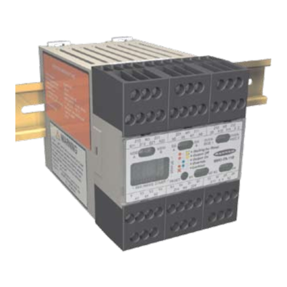
Models MMD-TA-11B and MMD-TA-12B
Features
• Compact, 67.5 mm DIN-mounted housing with
plug-in terminal blocks.
®
• For use with EZ-SCREEN
Output Signal Switching
Device (OSSD) outputs or MINI-SCREEN
®
SCREEN
, MACHINE-GUARD
devices with hard relay contact safety output(s) or
+24V dc (PNP) outputs.
• Monitors two or four inputs to automatically suspend
the safety function of a safeguarding device.
• Can be used as a dual controller when muting
function is not used.
• Safety (protective) Stop Interface (SSI) for connection
of supplemental safeguarding devices, E-stops, or
other devices.
• Category 2, 3, or 4 hookup per ISO 13849-1/-2.
• Selectable external device monitoring (EDM).
• Selectable Automatic or Monitored Manual Reset
provides flexibility for point-of-operation, area, or
perimeter guarding.
• Two N.O. safety contacts (model MMD-TA-11B) or
diverse-redundant solid-state safety outputs (model
MMD-TA-12B).
• Status LEDs and two-digit Diagnostic Display indicate
module status.
• Easy configuration for:
Auto/manual reset
One-/two-channel EDM
One-/two-direction muting
Selectable mute enable
Monitored/non-monitored mute lamp
Selectable backdoor timer
Selectable mute on power-up
Phone: 800.894.0412 - Fax: 888.723.4773 - Web: www.clrwtr.com - Email: info@clrwtr.com
Muting Module
Instruction Manual
®
, MICRO-
®
, or other safety
Section 1
Section 2
Section 3
Section 4
Section 5
Section 6
Section Contents
Introduction . . . . . . . . . . . . . . . . . . . . . . . . . . . . . . . . . . . . . Page 1
Components and Specifications . . . . . . . . . . . . . . . . . . . . . Page 8
System Installation . . . . . . . . . . . . . . . . . . . . . . . . . . . . . . . Page 12
Operating Instructions . . . . . . . . . . . . . . . . . . . . . . . . . . . . . Page 39
Troubleshooting and Maintenance . . . . . . . . . . . . . . . . . . . Page 40
Checkout Procedures . . . . . . . . . . . . . . . . . . . . . . . . . . . . . Page 42
Appendix . . . . . . . . . . . . . . . . . . . . . . . . . . . . . . . . . . . . . . . Page 45
Advertisement
Table of Contents

Related Manuals for Banner MMD-TA-12B


Summarization of Contents
Overview
Introduction
Explains the purpose and intended use of the Muting Module.
Operating Status LEDs and Diagnostic Display
Describes the module's status indicators and diagnostic display.
Automatic or Monitored Manual Reset Select
Explains how to select between automatic and manual reset modes.
Lockout Conditions
Describes conditions that cause the module to enter a lockout state.
Control Reliability: Redundancy and Self-Checking
Explains the module's design for safety and redundancy.
Mutable Safety Stop Interface (MSSI)
Details the Muteable Safety Stop Interface (MSSI) input.
Safety (Protective) Stop Interface (SSI)
Describes the Safety Stop Interface (SSI) for additional devices.
OSSD Outputs
Explains the Output Signal Switching Device (OSSD) safety outputs.
Auxiliary Output (Aux)
Describes the non-safety-related Auxiliary (Aux) output.
External Device Monitoring (EDM)
Details the External Device Monitoring (EDM) feature.
Mute Inputs (M1-M4) and Mute Devices
Explains the mute device inputs and their requirements.
Mute Enable (ME)
Describes the Mute Enable input function.
Mute Lamp Output (ML)
Details the Mute Lamp Output for status indication.
Backdoor Timer
Explains the Backdoor Timer for limiting mute duration.
Mute on Power-Up
Describes the Mute on Power-Up function.
Override
Explains the Override function for clearing obstructions.
One-Way/Two-Way Muting
Details one-way vs. two-way muting configurations.
Designated and Qualified Persons
Defines designated and qualified persons for safety procedures.
Components and Specifications
Specifications
Lists the technical specifications for the module.
Specifications, continued
Continues the technical specifications for the module.
Specifications, continued
Continues the technical specifications for the module.
Application Notes
Provides notes on mute timing and applications.
Accessories
Lists available accessories for the module.
Dimensions
Shows the physical dimensions of the module.
System Installation
Appropriate Application
Discusses suitable applications and limitations for the module.
Muting Application Design
Describes typical applications where muting is used.
Use of Corner Mirrors with Optical Safety Systems
Explains why corner mirrors are not allowed for muting.
Multiple Presence-Sensing Safety Devices (PSSDs)
Discusses muting multiple PSSDs or sensing fields.
Pass-Through Hazards
Explains pass-through hazards and how to mitigate them.
Installing the Module
Details the physical installation of the module.
Muting Module Configuration
Explains how to configure the module using DIP switches.
Connection Terminals and Functions
Details terminal connections and their functions.
Installing Input Devices
Covers the installation of various input devices.
Manual Reset Switch
Details the installation and placement of the manual reset switch.
Muting Devices
Explains requirements and types of muting devices.
Mute Lamp Output (ML)
Describes the Mute Lamp Output hookup and configuration.
Auxiliary Output (AUX)
Details the Auxiliary Output hookup for both models.
Override Switch Hookup
Explains how to connect override switches.
SSI and MSSI Interfacing
Covers interfacing SSI and MSSI with safety systems.
Safety Circuit Integrity and ISO 13849-1 (EN954-1)
Discusses safety circuit integrity levels and ISO standards.
Generic SSI and MSSI Hookups
Provides generic hookup examples for SSI and MSSI.
Category 4
Details Category 4 requirements for SSI/MSSI interfacing.
SSI Emergency Stop Switch Device Hookup
Explains how to hook up E-stop switches to SSI.
Category 3
Details Category 3 requirements for E-stop switches.
Category 4
Details Category 4 requirements for E-stop switches.
SSI/MSSI Interlocked Guard or Gate Hookup
Describes interfacing SSI/MSSI with interlocked guards/gates.
Category 2
Explains Category 2 requirements for interlocked guards.
Category 3
Explains Category 3 requirements for interlocked guards.
Category 4
Explains Category 4 requirements for interlocked guards.
SSI Supplemental Safety System Hookup
Shows an example hookup for supplemental safety systems.
Machine Interface – Initial Hookup and Checkout
Details initial hookup and checkout procedures for the machine interface.
Temporary Power and Initial Checkout
Covers temporary power-up and initial checkout steps.
Permanent Hookup to the Guarded Machine
Explains permanent connections to the guarded machine.
Mute Enable Hookup
Details the hookup procedure for the Mute Enable input.
External Device Monitoring (EDM) Hookup
Explains the hookup configurations for EDM.
OSSD Output Connections
Covers the connection of OSSD outputs to machine inputs.
FSD Interfacing Connections
Details interfacing Final Switching Devices (FSDs).
Dual-Channel Control
Explains dual-channel control for FSDs.
Single-Channel Control
Explains single-channel control for FSDs.
Commissioning Checkout
Outlines the commissioning checkout procedure.
Operating Instructions
Security Protocol
Details security measures for the module's enclosure.
Periodic Checkout Requirements
Emphasizes the need for regular checkout procedures.
Normal Operation
Describes normal operation and status indicator conditions.
Troubleshooting and Maintenance
Troubleshooting Lockout Conditions
Explains how to identify and clear lockout conditions.
Diagnostic Display
Describes the diagnostic display for problem diagnosis.
Effects of Electrical Noise
Discusses how electrical noise can affect the module.
Repairs
Provides instructions for returning the module for repair.
Periodic Checkout Procedures
Schedule of Checkouts
Outlines the schedule for different types of checkouts.
Commissioning Checkout
Details the commissioning checkout procedure.
Daily Checkout
Describes the daily checkout procedure.
Semi-Annual Checkout
Details the semi-annual checkout procedure.
Appendix A. Mute Timing Sequences
Muting Sequence with Two Muting Devices
Shows timing for two muting devices.
Muting Sequence with Four Muting Devices
Shows timing for four muting devices.
Appendix B. Typical Muting Applications
Entry/Exit Applications
Describes Entry/Exit applications with muting.
Robot Load/Unload Station Application
Details robot load/unload station muting applications.
Turret Table Application
Describes turret table muting applications.
Power Press Applications
Explains muting applications for power presses.
Glossary of Terms
ANSI (American National Standards Institute)
Defines ANSI and its role in technical standards.
Auto Power-Up
Defines the Auto Power-Up feature of safety light screens.
Blocked Condition
Defines a blocked condition in a safety light screen.
Brake
Defines a brake as a mechanism for stopping motion.
Clutch
Defines a clutch as a mechanism for transmitting torque.
Control Reliability
Defines Control Reliability for control systems.
CSA: Canadian Standards Association
Defines CSA and its role as a testing agency.
Defined Area
Defines the "screen of light" generated by a safety light screen.
Designated Person
Defines a Designated Person for checkout procedures.
Emitter
Defines the light-emitting component of a safety light screen.
External Device Monitoring (EDM)
Defines External Device Monitoring (EDM).
Failure to Danger
Defines a failure that delays machine safety system arrest.
Final Switching Device (FSD)
Defines the component that interrupts circuits to the MPCE.
FMEA (Failure Mode and Effect Analysis)
Defines FMEA testing procedure.
Forced-Guided Contacts
Defines relay contacts that are mechanically linked.
Guarded Machine
Defines the machine protected by a safety system.
Hard Guard
Defines physical barriers to prevent entry into hazardous areas.
Hazardous Area
Defines an area posing an immediate physical hazard.
Hazard Point
Defines the closest reachable point of a hazardous area.
Internal Lockout
Defines an internal safety system lockout condition.
Key Reset (Manual Reset)
Defines a key-operated switch for resetting safety systems.
Latch Condition
Defines the response of safety outputs to object entry.
Lockout Condition
Defines a system condition causing safety outputs to turn OFF.
Machine Operator
Defines an individual who controls machine operation.
Machine Primary Control Element (MPCE)
Defines the electrically-powered element controlling machine motion.
Minimum Object Sensitivity (MOS)
Defines the minimum diameter object a safety system can detect.
Muting
Defines the automatic suspension of a safety function.
OFF State
Defines the state where an output circuit is interrupted.
ON State
Defines the state where an output circuit is complete.
OSHA (Occupational Safety and Health Administration)
Defines OSHA and its regulatory role.
OSSD
Defines Output Signal Switching Device for initiating stop signals.
Pass-Through Hazard
Defines a hazard situation where personnel pass through a safeguard.
Point-of-Operation
Defines the location where machine function is performed.
Point-of-Operation Guarding
Defines safeguards protecting personnel at the point of operation.
Qualified Person
Defines an individual qualified for safety system tasks.
Receiver
Defines the light-receiving component of a safety light screen.
Reset
Defines the action to restore safety outputs to ON state.
Self-Checking (Circuitry)
Defines circuitry that verifies its own components.
Separation Distance (Safety Light Screen)
Defines minimum distance for hazard stopping before reach.
Specified Test Piece
Defines an object used to block a light beam for testing.
Supplemental Guarding
Defines additional guarding to prevent access.
Test Piece
Defines an object used to test safety light screen operation.
Trip Condition
Defines safety output response to object entry.
TUV (Technischer Überwachungsverein)
Defines TUV as a testing/certification organization.
UL (Underwriters Laboratory)
Defines UL as a third-party testing organization.
Need help?
Do you have a question about the MMD-TA-12B and is the answer not in the manual?
Questions and answers