Rohde & Schwarz ZVB 4 Service Manual
Vector network analyzers
Hide thumbs
Also See for ZVB 4:
- Quick start manual (102 pages) ,
- Manual (156 pages) ,
- Operating manual (813 pages)

Related Manuals for Rohde & Schwarz ZVB 4


Summary of Contents for Rohde & Schwarz ZVB 4
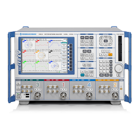
- Page 1 Service Manual Vector Network Analyzers ® R&S ZVB 4 / ZVB 8 / ZVB 14 / ZVB 20 1145.1010.04/06 / 08/10 / 14/17/19 / 20/23/25 Test and Measurement 1145.1078.82-04...
-
Page 2: Documents
® R&S is a registered trademark of Rohde & Schwarz GmbH & Co. KG. Trade names are trademarks of the owners. The instrument includes software developed by the OpenSSL Project for use in the OpenSSL Toolkit (http://www.openssl.org/). It includes cryptographic software written by Eric Young (eay@cryptsoft.com) and software written by Tim Hudson (tjh@cryptsoft.com). -
Page 3: Alignment
R&S ZVB Chapter Overview Chapter Overview Safety Instructions Spare Parts Express Service List of R&S Representatives Contents of Manuals for Vector Network Analyzers R&S ZVB Service and Repair Chapter 1: Performance Test Chapter 2: Alignment Chapter 3: Repair Chapter 4: Software Update / Installation of Options Chapter 5: Documents... - Page 5 R&S ZVB Index Index Alignment ............... 2.3 Hard Disk Frequency accuracy..........2.6 Replacement ............3.27 Frequency response correction ......2.7, 2.9 Hard Disk battery Level accuracy ............2.9 Replacement ............3.27 Manual ..............2.4 Reference frequency..........2.6 Test equipment ............2.4 Instrument construction ..........3.1 Battery Replacement............
-
Page 6: Table Of Contents
Index R&S ZVB Level linearity ............ 1.5, 1.8 Protocol ..............1.18 Performance Test............1.1 Shipping Frequency accuracy........1.16, 1.17 Instrument ..............5.1 Power cables ..............5.4 Module ..............5.1 Power supply Software update .............4.1 Function ..............3.19 Spare parts Replacement............3.36 electrical parts ..........5.5, 5.19 Replacement............ - Page 7 Procedure in Case of Service and Ordering of Spare Parts This section contains information on shipping an instrument to your service center and ordering spare parts. Please contact your local Rohde & Schwarz service center if you need service or repair work of your equipment or to order spare parts.
- Page 8 Ordering Spare Parts To deliver spare parts promptly and correctly, we need the following information: ● Stock number (see list of spare parts in chapter "Documents") ● Designation ● Component number according to list of spare parts ● Number of pieces ●...
- Page 9 FSQ FVREF "Überschrift 2" \* MERGEFORMAT Fehler! Form atvorlage nicht definiert. R&S ZVB Contents Table of Contents – Chapter 1 "Performance Test" 1 Performance Test....................1.1 Preliminary Remarks ........................1.1 Test Equipment and Accessories ....................1.2 Performance Test ..........................1.4 Checking the Frequency Uncertainty ..................1.4 Checking the Harmonics ......................1.5 Checking the Maximum Output Power..................1.6 Checking the Accuracy of Output Power..................1.7...
- Page 11 R&S ZVB Preliminary Remarks 1 Performance Test Preliminary Remarks • The required characteristics of the network analyzer are checked after a warm–up time of at least 60 minutes; this ensures that the guaranteed data is met. • The values stated in the following sections are not guaranteed data; only the specifications in the data sheet are binding.
- Page 12 Performance Test R&S ZVB Test Equipment and Accessories Item Type of Recommended characteristics or Recommended R&S Application equipment features model Order No. Spectrum a) Counter mode: R&S FSU 26 1129.9003.26 Frequency uncertainty analyzer Min. resolution: 100 Hz Harmonics –6 Max. rel. frequency deviation: 10 Output linearity b) Linearity Input linearity...
- Page 13 R&S ZVB Test Equipment and Accessories Item Type of Recommended characteristics or Recommended R&S Application equipment features model Order No. Test cable 3.5mm(male) – 3.5 mm (female), Frequency uncertainty approx. 1.5 m Harmonics Matching port 1 to port 4 Power measurement uncertainty Input linearity on R&S ZVB14/20...
-
Page 14: Performance Test
Performance Test R&S ZVB Performance Test Compare with data sheet Checking the Frequency Uncertainty Instrument: Spectrum analyzer (see Chapter “Test Equipment“, Item1) Test cable (see Chapter “Test Equipment“, Item7) Test setup: Connect the spectrum analyzer to (port 2 to port 4) Spectrum analyzer settings: –... -
Page 15: Checking The Harmonics
R&S ZVB Performance Test Checking the Harmonics Instrument: Spectrum analyzer (see Chapter "Test Equipment", Item1) Test cable (see Chapter “Test Equipment", Item7) Test setup: Connect the spectrum analyzer to port1 (port 2 to port 4) Spectrum analyzer settings: Note: Synchronize the reference oscillators in the spectrum analyzer and in the ®... -
Page 16: Checking The Maximum Output Power
Performance Test R&S ZVB Checking the Maximum Output Power Instrument: Power sensor or Power meter with power sensor (see Chapter “Test Equipment“, Item2) Test setup: Connect power sensor to port1 (port 2 to port 4) Power sensor settings: For measurement frequencies, see Performance Test Report {f R&S ZVB settings: –... -
Page 17: Checking The Accuracy Of Output Power
R&S ZVB Performance Test Checking the Accuracy of Output Power Instrument: Power sensor or Power meter with power sensor (see Chapter “Test Equipment“, Item2) Test setup: Connect the power sensor to port 1 (port 2 to port 4) Power sensor settings: For measurement frequencies, see Performance Test Report {f R&S ZVB settings: –... -
Page 18: Checking The Output Linearity
Performance Test R&S ZVB Checking the Output Linearity Instrument: Spectrum analyzer (see Chapter “Test Equipment“, Item1) Test cable (see Chapter “Test Equipment“, Item7) Test setup: Connect the spectrum analyzer to port 1(port 2 to port 4) Spectrum analyzer settings: Note: Synchronize the reference oscillators in the spectrum analyzer and in the ®... -
Page 19: Checking The Power Measurement Uncertainty
R&S ZVB Performance Test Checking the Power Measurement Uncertainty Instrument: Power sensor or Power meter with power sensor (see Chapter “Test Equipment“, Item2) Signal generator (see Chapter “Test Equipment“, Item5) Power splitter (see Chapter “Test Equipment“, Item6) Calibration kit (see Chapter “Test Equipment“, Item4) Test cable (see Chapter “Test Equipment“, Item7) Preparation/ Connect the signal generator to the power–splitter input using the test... -
Page 20: Checking The Input Linearity
Performance Test R&S ZVB Checking the Input Linearity Instrument: Calibration kit (see Chapter “Test Equipment“, Item4) ® R&S ZVB settings: – [ Preset ] – [ Meas : Ratios: b1/a1 Src Port 1] [ Meas : Ratios: b2/a2 Src Port 2] [ Meas : Ratios: b3/a3 Src Port 3] [ Meas : Ratios: b4/a4 Src Port 4] –... -
Page 21: Checking The Input Noise Level
R&S ZVB Performance Test Checking the Input Noise Level Test equipment Calibration kit (see Chapter “Test Equipment“, Item4) Test setup: Connect the Match Male from the calibration kit to port 1 (port 2 to port 4) ® R&S ZVB settings: –... -
Page 22: Checking The Matching (Raw)
Performance Test R&S ZVB Checking the Matching (raw) Instrument: Calibration kit (see Chapter “Test Equipment“, Item4) Test cable (see Chapter “Test Equipment“, Item7) ® 1. Preparation/ Connect the test cable to port 1 on the R&S ZVB and perform a 1–port test setup: calibration at the end of the cable. -
Page 23: Checking The Dynamic Range
R&S ZVB Performance Test Checking the Dynamic Range Test equipment: Calibration kit N (see Chapter “Test Equipment“, Item 4) Test setup: Connect Short Male to port1 and port 2 (port 3 and port 4) (use Short Female with Through Male as a second Short Male) ®... -
Page 24: Checking The Dynamic Range Reduced Due To Spurious
Performance Test R&S ZVB Checking the Dynamic Range reduced due to Spurious Only with Instruments fitted with Synthesizers 1145.xxxx Test equipment: Calibration kit N (see Chapter “Test Equipment“, Item4) Test setup: Connect Short Male to port1 and port 2 (port 3 and port 4) (use Short Female with Through Male as a second Short Male) ®... -
Page 25: Checking The Dc Measurement Inputs
R&S ZVB Performance Test Checking the DC Measurement Inputs DC Power Supply NGSM 32/10 (see Chapter “Test Equipment“, Item9) Test equipment: Multimeter R&S URE3 (see Chapter “Test Equipment“, Item10) DC cable (see Chapter “Test Equipment“, Item11) Test setup: Connect the Power Supply to the Input DC MEAS 1V (DC MEAS 10V) of R&S ZVB using the DC cable. -
Page 26: Checking The Optional R&S Zvb20-B80 Low Frequency Extension
Performance Test R&S ZVB Checking the optional R&S ZVB20-B80 Low Frequency Extension Test equipment: Test port cable Test Setup: Connect test port cable between: a) Test Port 1 and REF IN 1 b) Test Port 1 and MEAS IN 1 c) Test Port 2 and REF IN 2 d) Test Port 2 and MEAS IN 2 ®... -
Page 27: Checking The Optional R&S Zvb20-B81 External Testset
R&S ZVB Performance Test Checking the optional R&S ZVB20-B81 External Testset Test equipment: R&S ZVA24 with option R&S ZVA24-B16 and test port cable, two Short standards, and a Match standard. Test Setup: Connect R&R ZVB20-B81 with R&R ZVA24 and a) connect Shorts at PORT 1 and PORT 2 of R&S ZVB20-B81 b) connect Match at PORT 1 or PORT 2 respectively of R&S ZVB20-B81 c) connect test port cable between PORT 1 and PORT 2 of R&S ZVB20-B81 d) connect Shorts at PORT 1 and PORT 2 of R&S ZVB20-B81... -
Page 28: Performance Test Report
Performance Test Report R&S ZVB Performance Test Report Table 1–1: Performance Test Report ROHDE & SCHWARZ Performance Test Report R&S ZVB Version Model (R&S ZVB4 / R&S ZVB8/R&S ZVB14 / R&S ZVB20) Item number: 1045. Serial number Tested by: Date: Signature: General: All Tables apply to port1;... - Page 29 R&S ZVB Performance Test Report Parameter Covered on Min. value Actual value Max. value Unit Measurement tolerance Port __ Page 1.5 1 dB Harmonics Source power +8 dBm Freq. Harmonics 2.1 GHz 4.2 GHz ________ 6.3 GHz ________ –20 –20 2.5 GHz 5.0 GHz ________ 7.5 GHz...
- Page 30 Performance Test Report R&S ZVB Parameter Covered on Min. value Actual value Max. value Unit Measurement tolerance Port __ Page 1.6 1 dB Max. output power w.o. Opt. B21 /B22/ Test frequency R&S ZVB4 and ZVB8: 300 kHz ________ 1 MHz ________ 2 MHz ________...
- Page 31 R&S ZVB Performance Test Report Parameter Covered on Min. value Actual value Max. value Unit Measurement tolerance Port __ Page 1. 1 dB Max. output power w. Opt. B21 /B22/ B23 Test frequency R&S ZVB4 and ZVB8: 300 kHz ________ 1 MHz ________ 2 MHz...
- Page 32 Performance Test Report R&S ZVB Parameter Covered on Min. value Actual value Max. value Unit Measurement tolerance Port __ Page 1.7 0. dB Power Uncertainty output power –10 dBm Test frequency R&S ZVB4 and ZVB8: 300 kHz – 2 ________ 1 MHz –...
- Page 33 R&S ZVB Performance Test Report Parameter Covered on Min. value Actual value Max. value Unit Measurement tolerance Port __ Page 1.8 0.06 dB Power linearity w. o. Opt. B21/B22/B23 Reference –10 dBm ZVB4/8 (ZVB14/20): Freq. Level 51 MHz 20 dB –...
- Page 34 Performance Test Report R&S ZVB Parameter Covered on Min. value Actual value Max. value Unit Measurement tolerance Port __ Page 1.8 0.06 dB Power linearity w. o. Opt. B21/B22/B23 Reference –10 dBm Freq. Level 2.1 GHz 20 dB – 0.8 ________ 15 dB –...
- Page 35 R&S ZVB Performance Test Report Parameter Covered on Min. value Actual value Max. value Unit Measurement tolerance Port __ Page 1.8 0.06 dB Power linearity w. o. Opt. B21/B22/B23 Reference –10 dBm R&S ZVB8, ZVB14, ZVB20: Freq. Level 6 GHz 20 dB –...
- Page 36 Performance Test Report R&S ZVB Parameter Covered on Min. value Actual value Max. value Unit Measurement tolerance Port __ Page 1.8 0.06 dB Power linearity w. o. Opt. B21/B22/B23 Reference –10 dBm Freq. Level 13 GHz 20 dB – 0.8 ________ 15 dB –...
- Page 37 R&S ZVB Performance Test Report Parameter Covered on Min. value Actual value Max. value Unit Measurement tolerance Port __ Page 1.8 0.06 dB Power linearity w. Opt. B21/B22/B23 R&S ZVB4 and ZVB8 only Reference –10 dBm R&S ZVB4/8 (R&S ZVB14/20): Freq.
- Page 38 Performance Test Report R&S ZVB Parameter Covered on Min. value Actual value Max. value Unit Measurement tolerance –90 dB Page 1.8 – 3 ________ 0.06 dB Port __ Power linearity w. Opt. B21/B22/B23 R&S ZVB4 and ZVB8 only Reference –10 dBm Freq.
- Page 39 R&S ZVB Performance Test Report Parameter Covered on Min. value Actual value Max. value Unit Measurement tolerance –85 dB – 3 ________ –90 dB – 3 ________ Port __ Page 1.8 0.06 dB Power linearity w. Opt. B21/B22/B23 R&S ZVB4 and R&S ZVB8 only Reference –10 dBm Freq.
- Page 40 Performance Test Report R&S ZVB Parameter Covered on Min. value Actual value Max. value Unit Measurement tolerance –80 dB – 3 ________ –85 dB – 3 ________ –90 dB – 3 ________ Page 1.8 Port __ 0.06 dB Power linearity w.
- Page 41 R&S ZVB Performance Test Report Parameter Covered on Min. value Actual value Max. value Unit Measurement tolerance –75 dB – 3 ________ –80 dB – 3 ________ –85 dB – 3 ________ –90 dB – 3 ________ Port __ Page 1.8 0.06 dB Power linearity w.
- Page 42 Performance Test Report R&S ZVB Parameter Covered on Min. value Actual value Max. value Unit Measurement tolerance Page 1.9 0.2 dB Port __ Power measurement uncertainty Test frequency R&S ZVB4 and ZVB8: 300 kHz – 1 ________ 1 MHz – 1 ________ 2 MHz –...
- Page 43 R&S ZVB Performance Test Report Parameter Covered on Min. value Actual value Max. value Unit Measurement tolerance Port __ Page 1.10 0.06 dB Input linearity Reference –10 dBm 50 MHz 20 dB –0.1 ________ 15 dB –0.1 ________ 10 dB –0.1 ________ 5 dB...
- Page 44 Performance Test Report R&S ZVB Parameter Covered on Min. value Actual value Max. value Unit Measurement tolerance Port __ Page 1.10 0.06 dB Input linearity Reference –10 dBm R&S ZVB4, ZVB8: 4 GHz 20 dB –0.1 ________ 15 dB –0.1 ________ 10 dB –0.1...
- Page 45 R&S ZVB Performance Test Report Parameter Covered on Min. value Actual value Max. value Unit Measurement tolerance Port __ Page 1.10 0.06 dB Input linearity Reference –10 dBm R&S ZVB14, ZVB20: 8.1 GHz 15 dB –0.3 ________ 10 dB –0.1 ________ 5 dB –0.1...
- Page 46 Performance Test Report R&S ZVB Parameter Covered on Min. value Actual value Max. value Unit Measurement tolerance Port __ Page 1.11 Input noise level Test frequency R&S ZVB4 and ZVB8: 423.450 kHz ________ –70 1.12345 MHz ________ –70 2.12345 MHz ________ –70 5.12345 MHz...
- Page 47 R&S ZVB Performance Test Report Parameter Covered on Min. value Actual value Max. value Unit Measurement tolerance Page 1.12 1 dB Port __ Matching (raw) Test frequency R&S ZVB4, ZVB8: 300 kHz ________ 1 MHz ________ 2 MHz ________ 5 MHz ________ R&S ZVB4/8, (R&S ZVB14/20):...
- Page 48 Performance Test Report R&S ZVB Parameter Covered on Min. value Actual value Max. value Unit Measurement tolerance Port __ Page 1.13 Dynamic range R&S ZVB4/8 2–port unit w. o. Opt. B21/22/23 Test frequency 300 kHz ________ 1 MHz ________ 2 MHz ________ 5 MHz ________...
- Page 49 R&S ZVB Performance Test Report Parameter Covered on Min. value Actual value Max. value Unit Measurement tolerance Port __ Page 1.13 Dynamic range R&S ZVB4/8 3–port and 4–port unit w. o. Opt. B21/22/23 Test frequency 300 kHz ________ 1 MHz ________ 2 MHz ________...
- Page 50 Performance Test Report R&S ZVB Parameter Covered on Min. value Actual value Max. value Unit Measurement tolerance Port __ Page 1.13 Dynamic range R&S ZVB4/8 2–port unit w. Opt. B21/22/23 Test frequency 300 kHz ________ 1 MHz ________ 2 MHz ________ 5 MHz ________...
- Page 51 R&S ZVB Performance Test Report Parameter Covered on Min. value Actual value Max. value Unit Measurement tolerance Port __ Page 1.13 Dynamic range R&S ZVB4/8 3–port and 4–port unit w. Opt. B21/22/23 Test frequency 300 kHz ________ 1 MHz ________ 2 MHz ________ 5 MHz...
- Page 52 Performance Test Report R&S ZVB Parameter Covered on Min. value Actual value Max. value Unit Measurement tolerance Port __ Page 1.13 Dynamic range R&S ZVB14, R&S ZVB20 Test frequency 10 MHz ________ 20 MHz ________ 50 MHz ________ 100 MHz ________ 200 MHz ________...
- Page 53 R&S ZVB Performance Test Report Parameter Covered on Min. value Actual value Max. value Unit Measurement tolerance Port ___ Page 1.14 Dynamic range reduced due to spurious R&S ZVB4, ZVB8 only: Test frequency 16 MHz ________ 32 MHz ________ 48 MHz ________ 96 MHz ________...
- Page 54 Performance Test Report R&S ZVB Parameter Covered on Min. value Actual value Max. value Unit Measurement tolerance Accuracy Page 1.15 1 mV DC meas 1 V Pos. Input –1000 m V – 27.5 ________ + 27.5 –300 mV – 10.0 ________ + 10.0 –10 mV...
- Page 55 R&S ZVB Performance Test Report Parameter Covered on Min. value Actual value Max. value Unit Measurement tolerance Opt. R&S ZVB20-B80 Page 1.16 a1(2 MHz) – a1(10 MHz) ________ b1(2 MHz) – b1(10 MHz) ________ a2(2 MHz) – a2(10 MHz) ________ b2(2 MHz) –...
-
Page 57: Frequency Accuracy
R&S ZVB Table of Contents - Alignment Table of Contents - Chapter 2 "Alignment" 2 Alignment......................2.3 Service Menu ...........................2.3 Manual Alignment and Recording Correction Values ..............2.4 Test Equipment ........................2.4 Aligning the Frequency Accuracy.....................2.6 Aligning the DC Inputs......................2.7 Correction Value Recording and Factory System Error Calibration .........2.9 Installation of the Alignment Program ..................2.9 Checking the Gauge.........................2.9 1145.1078.82... - Page 58 Table of Contents - Alignment R&S ZVB 1145.1078.82 I-2.2...
-
Page 59: Alignment
R&S ZVB Manual Alignment and Recording Correction Values 2 Alignment This chapter describes the alignment of the frequency reference and the recording of correction data after a board has been replaced. The following manual alignments or corrections can be performed on the ZVB: •... - Page 60 Manual Alignment and Recording Correction Values R&S ZVB Manual Alignment and Recording Correction Values In the sequel, the test equipment and the instrument preparations required to manually align the ZVB and each of the alignments are described. Preliminary remarks The analyzer must be allowed to warm up for at least 30 minutes before alignment. This is the only way of ensuring that the guaranteed data are met.
- Page 61 R&S ZVB Manual Alignment and Recording Correction Values Item Type of equipment Recommended Recommended R&S Order No. Application specifications model Calibration kit N calibration kit R&S ZV-Z21 1085.7099.02 Recording correction values on R&S ZVB4/8 Calibration kit 3.5 mm calibration kit R&S ZV-Z23 1085.7099.02 Recording correction...
-
Page 62: Manual Alignment And Recording Correction Values
Manual Alignment and Recording Correction Values R&S ZVB Aligning the Frequency Accuracy Test equipment Spectrum analyzer (section "Test Equipment", item 1): Error <1x10 Test setup: Connect the spectrum analyzer to the 10-MHz reference output at the rear of the ZVB. ZVB settings: Select internal reference MENU : System: Reference Internal... -
Page 63: Aligning The Dc Inputs
R&S ZVB Manual Alignment and Recording Correction Values Writing data to the hard disk: Change to computer application Select path C:\Documents and Settings\AllUsers\ApplicationData\Rohde&Schwarz\NWA\data\eeprom\ FR\config.ini Transform data format to decimal Write decimal data to [ TUNE ] 128_PRETUNE = … (without option ZVAB-B4) OCXO_TUNE = …... - Page 64 Manual Alignment and Recording Correction Values R&S ZVB The values that have been obtained in this way are now written to the hard disk using the Service Functions described below and then transferred to the EEprom of network controller1. Example illustrating DC Meas 1 V: When +1 V is applied, V 1 = 1.023 V is displayed by the R&S ZVB;...
-
Page 65: Correction Value Recording And Factory System Error Calibration
R&S ZVB Manual Alignment and Recording Correction Values Correction Value Recording and Factory System Error Calibration Required test equipment (see Table 2-1): • PC with IEC/IEEE bus interface • ZVAB-Service program • Power meter with power sensor • Signal generator •... -
Page 67: Disk Drive
R&S ZVB Instrument Construction and Function Description Table of Contents - Chapter 3 "Repairs" Repairs......................3.1 Instrument Construction and Function Description ................3.1 Block Diagram ..........................3.2 Description of the Block Diagram .....................3.11 Board Replacement ..........................3.20 Board Overview ........................3.21 Replacing Front Module Controller A90 ...................3.22 Replacing the Lithium Battery on the Front Module Controller..........3.25 Replacing Hard Disk A60......................3.27 Replacing LCD A70 and the DC/AC Converter ................3.28... - Page 68 Instrument Construction and Function Description R&S ZVB Troubleshooting - Boot Error ....................3.57 Troubleshooting with the Selftest .....................3.58 Checking the Temperature Sensors ..................3.63 Service Functions ........................3.64 Determining which Boards are defective ..................3.68 Board Test ..........................3.69 Testing the frequency reference board..................3.70 Testing the Synthesizer Board....................3.71 Testing the Reflectometer RM8 ....................3.74 Testing the Reflectometer RM20 .....................3.78 Testing the LO Divider Board ....................3.82...
-
Page 69: Repairs
R&S ZVB Instrument Construction and Function Description 3 Repairs This chapter describes the R&S ZVB`s construction, simple procedures for repairs, troubleshooting and board replacement. A selftest which checks the diagnostic voltages of the board and indicates limit violations is provided for troubleshooting and diagnostics. Chapter 4 of this service manual describes the installation of options and firmware updates. -
Page 70: Block Diagram
Instrument Construction and Function Description R&S ZVB Block Diagram See also Chapter 5, Annex and Drawings. BRIDGE PORT 1 OPTION GENERATOR GENERATOR PORT 1 PORT 1 ATTENUATOR 15 to 21 MHz PORT 1 RECEIVER REF PORT 1 RECEIVER MEAS PORT 1 NETCON NETCON ANALOG... - Page 71 R&S ZVB Instrument Construction and Function Description BRIDGE PORT 1 OPTION GENERATOR GENERATOR PORT 1 PORT 1 15 to 21 MHz ATTENUATOR PORT 1 RECEIVER REF PORT 1 RECEIVER MEAS PORT 1 NETCON NETCON ANALOG DIGITAL BRIDGE PORT 1 OPTION GENERATOR GENERATOR PORT 2...
- Page 72 Instrument Construction and Function Description R&S ZVB BRIDGE PORT 1 OPTION GENERATOR GENERATOR PORT 1 PORT 1 15 to 21 MHz ATTENUATOR PORT 1 RECEIVER REF PORT 1 RECEIVER MEAS PORT 1 NETCON NETCON ANALOG DIGITAL BRIDGE PORT 1 OPTION GENERATOR GENERATOR PORT 2...
- Page 73 R&S ZVB Instrument Construction and Function Description BRIDGE PORT 1 OPTION GENERATOR GENERATOR PORT 1 PORT 1 15 to 21 MHz ATTENUATOR PORT 1 RECEIVER REF PORT 1 RECEIVER MEAS PORT 1 NETCON NETCON ANALOG DIGITAL BRIDGE PORT 2 OPTION GENERATOR GENERATOR PORT 2...
- Page 74 Instrument Construction and Function Description R&S ZVB BRIDGE PORT 1 OPTION GENERATOR GENERATOR PORT 1 PORT 1 15 to 21 MHz ATTENUATOR PORT 1 RECEIVER REF PORT 1 RECEIVER MEAS PORT 1 NETCON NETCON ANALOG DIGITAL BRIDGE PORT 2 OPTION GENERATOR GENERATOR PORT 2...
- Page 75 R&S ZVB Instrument Construction and Function Description COUPLER PORT 1 GENERATOR PORT 1 (Driver+Doubler) PORT 1 15 to 21 MHz RECEIVER REF PORT 1 RECEIVER MEAS PORT 1 NETCON NETCON ANALOG DIGITAL GRAPHICS DISPLAY COUPLER PORT 2 GENERATOR PORT 2 (Driver+Doubler) PORT 2 RECEIVER...
- Page 76 Instrument Construction and Function Description R&S ZVB COUPLER PORT 1 GENERATOR PORT 1 (Driver+Doubler) 15 to 21 MHz PORT 1 RECEIVER REF PORT 1 RECEIVER MEAS PORT 1 NETCON NETCON ANALOG DIGITAL GRAPHICS DISPLAY COUPLER PORT 2 GENERATOR PORT 2 (Driver+Doubler) PORT 2 RECEIVER...
- Page 77 R&S ZVB Instrument Construction and Function Description GENERATOR (Driver+Doubler) 15 to 21 MHz PORT 1 RECEIVER REF PORT 1 RECEIVER MEAS PORT 1 NETCON NETCON ANALOG DIGITAL COUPLER PORT 2 GENERATOR (Driver+Doubler) PORT 2 RECEIVER REF PORT 2 RECEIVER MEAS PORT 2 FREQUENCY OPTION SYNTHESIZER 2...
- Page 78 Instrument Construction and Function Description R&S ZVB COUPLER PORT 1 GENERATOR (Driver+Doubler) 15 to 21 MHz PORT 1 RECEIVER REF PORT 1 RECEIVER MEAS PORT 1 NETCON NETCON ANALOG DIGITAL COUPLER PORT 2 GENERATOR (Driver+Doubler) PORT 2 RECEIVER REF PORT 2 RECEIVER MEAS PORT 2 FREQUENCY...
-
Page 79: Description Of The Block Diagram
R&S ZVB Instrument Construction and Function Description Description of the Block Diagram The block diagrams shown in Fig. 3-1 to Fig. 3-9 apply to the R&S ZVB4, R&S ZVB8, R&S ZVB14 and the R&S ZVB20 4 and 2 ports and to the R&S ZVB4 and R&S ZVB8 3 ports. The R&S ZVB is a vector network analyzer covering 300 kHz to 4 GHz (R&S ZVB4), 300 kHz to 8 GHz (R&S ZVB8), 10 MHz to 14 GHz (R&S ZVB14) or 10 MHz to 20 GHz (R&S ZVB20). - Page 80 Instrument Construction and Function Description R&S ZVB Receiver The receiver section has two channels (measurement channel and reference channel) and uses single conversion. Every channel contains a buffer amplifier, two mixers for each of the frequency ranges 300 kHz to 4 GHz and 4 GHz to 8 GHz (R&S ZVB8 only) with LO amplifiers and an IF amplifier. In the mixer, the input signal is directly converted to the IF range, approx 15 to 21 MHz.
- Page 81 R&S ZVB Instrument Construction and Function Description Network controller The network controller comprises two boards, the netcon analog and the netcon digital which are screwed together to form a single unit. The boards are four-channel – in other words, one network controller is required for two ports (2 measurement channels + 2 reference channels).
- Page 82 Instrument Construction and Function Description R&S ZVB Frequency reference The frequency reference board generates the highly stable and spectrally pure clock signals, required by the R&S ZVB, which can be phase-locked to external synchronisation signals. The various function blocks are: The 128 MHz VCXO (voltage-controlled crystal oscillator) which generates a stable, low-noise reference frequency for the synthesisers, for the A/D converters and for digital signal processing.
- Page 83 R&S ZVB Instrument Construction and Function Description Synthesizers The source signals for the generator signals associated with each port and the LO signal for the mixers on the receiver boards for each of the reflectometers are generated on the synthesizer board. One or two individual synthesizers are accommodated on a synthesizer board.
- Page 84 Instrument Construction and Function Description R&S ZVB DS Synthesizer to Reflectometer 1 (GEN) Synthesizer 9 kHz to 8GHz to Reflectometer 2 (GEN) to Reflectometer 3 (GEN) Synthesizer 9 kHz to 8GHz to Reflectometer 4 (GEN) 1145.1078.82 3.16...
- Page 85 R&S ZVB Instrument Construction and Function Description LO Synthesizer to Reflectometer 1 (LO) to Reflectometer 2 (LO) Synthesizer 15.625 MHz to 8025 MHz to Reflectometer 3 (LO) to Reflectometer 4 (LO) The synthesizer models are incorporated as follows in the various R&S ZVB models: LS Synth.
- Page 86 Instrument Construction and Function Description R&S ZVB LO divider The LO signal from the synthesizer is distributed via the LO-divider board between the receiver boards associated with the reflectometers that have been installed. A maximum of four reflectometers can be supplied with the LO signal in this way.
-
Page 87: Power Supply
R&S ZVB Instrument Construction and Function Description Power supply The power supply produces all the voltages required to power the R&S ZVB. It can be turned off with a switch on the instrument’s rear panel. The power supply is a primary-switched power supply with power factor correction (PFC) and standby circuit (+12 V standby). -
Page 88: Board Replacement
Instrument Construction and Function Description R&S ZVB Motherboard The motherboard supplies power to the boards and connects them to the control and data buses. A number of RF connections are also routed via the motherboard. As well as straight connections, a number of circuits are accommodated on the motherboard: Motherboard controller (MBCON) 28 V supply Preamplifier for the DC measurement inputs... -
Page 89: Board Overview
R&S ZVB Instrument Construction and Function Description Board Overview Table 3-1 Overview: Board Replacement Board Actions after replacement Function test Alignment Other Recording of correction values System error calibration Front module controller Check error log BIOS update Lithium battery Check error log Hard disk Check error log System error calibration... -
Page 90: Replacing Front Module Controller A90
Instrument Construction and Function Description R&S ZVB Replacing Front Module Controller A90 (See Chapter 5, Spare Parts List, Item 580, and drawings 1145.1010, 1145.1290) The front module controller is located behind the front unit. Opening the instrument and removing the front unit Turn off the instrument and disconnect from the mains. -
Page 91: Switching Foil
R&S ZVB Instrument Construction and Function Description Carefully insert the new front module controller on the motherboard and screw into place with 10 sems screws (590). Caution: With type FMR6 1091.2520.00, there is a danger of shorting between board components, tracks and screws (590). -
Page 92: Protocol
Instrument Construction and Function Description R&S ZVB Putting into operation Connect the mains cable and turn on at the power on switch. The instrument is now in standby mode. Insert the BIOS disk in the floppy disk drive. Turn on the instrument and wait for the first beep. Press the DEL key. The instrument should now display the setup menu. -
Page 93: Replacing The Lithium Battery On The Front Module Controller
R&S ZVB Instrument Construction and Function Description Replacing the Lithium Battery on the Front Module Controller (See Chapter 5, Spare Parts List, Item (582), and drawings 1145.1010, 1145.1290) The lithium battery is located on the front module controller behind the front unit. Caution Do not expose lithium batteries to high temperatures or naked flames. - Page 94 Instrument Construction and Function Description R&S ZVB Removing the lithium battery Carefully lift up and pull out the battery. Note: Lithium battery 3.4 V (dia. 20 mm * 3 mm) R&S Item No. 0858.2049.00 Front Module Controller Typ FMR6 Connector for rotary pulse generator Contact side of switching foil (keyboard) up Battery LAN 1 LAN 2...
-
Page 95: Replacing Hard Disk A60
R&S ZVB Instrument Construction and Function Description Putting into operation Connect the mains cable and turn on at the power switch. The instrument is now in standby mode. Select Service Level 2 (see Service Functions). When the instrument has been started, check the protocol file for errors: [ INFO : Error Log ] Replacing Hard Disk A60 (See Chapter 5, Spare Parts List, Item 710, and drawings 1145.1010 and 1145.1290) -
Page 96: Replacing Lcd A70 And The Dc/Ac Converter
Instrument Construction and Function Description R&S ZVB Replacing LCD A70 and the DC/AC Converter (See Chapter 5, Spare Parts List Items 910, 930 and drawings 1145.1290, 1145.1384) The LCD and the associated DC/AC converter are accommodated on a mounting plate. The connection to the front module controller is made with cables which should also be replaced individually. - Page 97 R&S ZVB Instrument Construction and Function Description Installing and putting into operation a new LCD or DC/AC converter Reinstall the new LCD or new DC/AC converter by reversing the disassembly procedure, refit all screws and reconnect the cables that have been disconnected (drawing 1145.1384). When replacing the display (921) or display cable (945), use a new adhesive label (946) to secure the cabling.
-
Page 98: Replacing Flexible Switch Board (Keyboard) A16 / Key Pad A15
Instrument Construction and Function Description R&S ZVB Replacing Flexible switch board (Keyboard) A16 / Key Pad A15 (See Chapter 5, Spare Parts List, Items 860, 870, 875, 877 and drawings 1145.1010, 1145.1384) The flexible switch board (keyboard) and key pad are located behind the front cover and the keyboard frame. - Page 99 R&S ZVB Instrument Construction and Function Description Note: Thread the foil cable’s connector through the slot in the mounting tray. Position the key pad so that the pins on the flexible switch board pass through the holes in the key pad. Place the rear of the display unit on the key pad (870, 875).
-
Page 100: Replacing The Front Cover
Instrument Construction and Function Description R&S ZVB Replacing the Front Cover (See Chapter 5, Spare Parts List, Items 300, 303, 306, 310, 313, 316, 317, 318, 320, 323, 324, 327, 328, 330 and drawing 1145.1010) The front cover is the outermost front panel with lettering. Each instrument type has its own front cover. Turn off the instrument and disconnect from the mains. -
Page 101: Replacing Disk Drive A30
R&S ZVB Instrument Construction and Function Description Replacing Disk Drive A30 (See Chapter 5, Spare Parts List, Item 670 and drawing 1145.1290) Opening the instrument and removing the disk drive Turn off the instrument and disconnect from the mains, screw off the 4 rear-panel feet (460) and pull off the enclosure (400) backwards. -
Page 102: Replacing Usb Board A40
Instrument Construction and Function Description R&S ZVB Replacing USB Board A40 (See Chapter 5, Spare Parts List, Item 1050 and drawings 1145.1290 and 1145.1384) The USB board is located behind the front cover and the keyboard frame next to the ON key. Opening the instrument and removing the USB-board Turn off the instrument and disconnect from the mains. -
Page 103: Replacing Power Supply A20
R&S ZVB Instrument Construction and Function Description Replacing Power Supply A20 (See Chapter 5, Spare Parts List, Items 790 and drawings 1145.1010, 1145.1290) The power supply is installed at the rear of the instrument frame. Removing the power supply Turn off the instrument and disconnect from the mains, screw off the 4 rear-panel feet (460) and pull off the enclosure (400) towards the rear. -
Page 104: Replacing Fuse Board A21
Instrument Construction and Function Description R&S ZVB Replacing Fuse board A21 (See Chapter 5, Spare Parts List, Item 735, and drawings 1145.1010, 1145.1290) The fuse board is installed on the left-hand side of the power supply. Removing the power supply and the fuse board Turn off the instrument and disconnect from the mains, screw off the 4 rear-panel feet (460) and pull off the enclosure (400) backwards. -
Page 105: Replacing A Fan
R&S ZVB Instrument Construction and Function Description Replacing a Fan (See Chapter 5, Spare Parts List, Item 15 and drawings 1145.1010, 1145.1290, 1145.1332) The fans, three in all, are located behind the right-hand side panel. Opening the instrument and removing the fan Turn off the instrument and disconnect from the mains, screw off the 4 rear-panel feet (460) and pull off the enclosure (400) backwards. -
Page 106: Replacing Motherboard A10
Instrument Construction and Function Description R&S ZVB Push the enclosure (400) back on and screw the 4 rear-panel feet (460) into position. Connect the mains cable, turn on at the mains switch and press the ON key. Replacing Motherboard A10 (See Chapter 5, Spare Parts List, Item 510 and drawings 1145.1010, 1145.1290) The motherboard is located on the base of the instrument. - Page 107 R&S ZVB Instrument Construction and Function Description Disconnect the cables to the LCD, the DC/AC illumination converter, the key pad (keyboard), the tachogenerator and, if necessary, the network connection to the front module controller. Note: When disconnecting cables, be especially careful with the cable to the keyboard. It is a foil cable and can only be removed when the locking device on the foil-cable connector is released.
- Page 108 Instrument Construction and Function Description R&S ZVB Installing the motherboard and reassembling the instrument N.B.: The motherboard is the passport of the instrument and unique for every unit. The Eprom on the motherboard contains the serial No. of the instrument. Pre-configured motherboards are not available.
-
Page 109: Replacing A Reflectometer Rm8 A510 To 540
R&S ZVB Instrument Construction and Function Description Replacing a Reflectometer RM8 A510 to 540 (See Chapter 5, Spare Parts List, Items 165, 170, 175 and drawing 1145.1010) The boards are located under the motherboard. Opening the instrument and removing the board Turn off the instrument and disconnect from the mains, screw off the 4 rear-panel feet (460) and pull off the enclosure (400) backwards. -
Page 110: Replacing Generator Board (R&S Zvb4/8 Only)
Instrument Construction and Function Description R&S ZVB Replacing Generator Board (R&S ZVB4/8 only) (See Chapter 5, Spare Parts List, Item 110 and drawing 1302.4960.08) Opening the instrument and removing the board Remove the Reflectometer (see chapter Replacing a Reflectometer RM8 A510 to A540) Remove the cover (130) Remove the fan cable Pull off the Generator Board (110) -
Page 111: Replacing Receiver Board (R&S Zvb4/8 Only)
R&S ZVB Instrument Construction and Function Description Replacing Receiver Board (R&S ZVB4/8 only) (See Chapter 5, Spare Parts List, Item 120, 125 and drawing 1302.4960.08) Opening the instrument and removing the board Remove the Reflectometer (see chapter Replacing a Reflectometer RM8 A510 to A540) Remove the cover (150) Pull off the Receiver Board (120, 125) Installing the board and reassembling the instrument... -
Page 112: Replacing Generator And Receiver Cover (R&S Zvb4/8 Only)
Instrument Construction and Function Description R&S ZVB Replacing Generator and Receiver Cover (R&S ZVB4/8 only) (See Service Circular 10028 and Chapter 5, Spare Parts List, Items 130, 150 and drawing 1302.4960.08) Opening the instrument and removing the cover Remove the Reflectometer (see chapter Replacing a Reflectometer RM8 A510 to A540) Remove the RM mount (200), 4 Screws (210) Remove the covers (130, 150) Installing the cover and reassembling the instrument... -
Page 113: Replacing The Inner Conductor Of A Port Connector (R&S Zvb4/8 Only)
R&S ZVB Instrument Construction and Function Description Replacing the Inner Conductor of a Port Connector (R&S ZVB4/8 only) (See Chapter 5, Spare Parts List, Item 110, and drawings 1145.1010, 1145.3593, 1145.3664) Opening the instrument and removing the reflectometer Remove the Reflectometer (see chapter Replacing a Reflectometer RM8 A510 to A540) Replacing the inner conductor Unscrew the N outer conductor with a spanner (narrow, SW 14 mm) and take out inner conductor unit. -
Page 114: Replacing The Bridge Unit (R&S Zvb4/8 Only)
Instrument Construction and Function Description R&S ZVB Replacing the Bridge Unit (R&S ZVB4/8 only) (See Chapter 5, Spare Parts List, drawings 1145.1010, 1145.3664, Item 100) Opening the instrument and removing the reflectometer Remove the Reflectometer (see chapter Replacing a Reflectometer RM8 A510 to A540) Removing the bridge unit Loosen the MEAS, REF and GEN cables (310, 320, 300) at both ends and disconnect at the bridge unit. -
Page 115: Replacing A Reflectometer Rm20 A510 To 540
R&S ZVB Instrument Construction and Function Description Replacing a Reflectometer RM20 A510 to 540 (See Chapter 5, Spare Parts List, Items 180, 185, 190 and drawings 1145.1010, 1302.4425) The boards are located under the motherboard. Opening the instrument and removing the board Turn off the instrument and disconnect from the mains, screw off the 4 rear-panel feet (460) and pull off the enclosure (400) backwards. -
Page 116: Replacing The Coupler Unit (R&S Zvb20 Only)
Instrument Construction and Function Description R&S ZVB Replacing the Coupler Unit (R&S ZVB20 only) (See Chapter 5, Spare Parts List, drawing 1145.1010, item 200) Opening the instrument and removing the coupler Turn off the instrument and disconnect from the mains, screw off the 4 rear-panel feet (460) and pull off the enclosure (400) backwards. -
Page 117: Replacing The Reflectometer Fan
R&S ZVB Instrument Construction and Function Description Replacing the Reflectometer Fan (See Chapter 5, Spare Parts List, Item 80, 190 and drawings 1145.1010, 1145.3664, 1145.4277) Remove the Reflectometer (see chapter Replacing a Reflectometer RMxx A510 to A540) Replacing the fan Disconnect the fan cable at the reflectometer. -
Page 118: Replacing Network Controller Board A130, A140
Instrument Construction and Function Description R&S ZVB Replacing Network Controller Board A130, A140 (See Chapter 5, Spare Parts List, Items 100, 105 and drawing1145.1010) The board is in the upper section of the instrument. Opening the instrument and removing the board Turn off the instrument and disconnect from the mains, screw off the 4 rear-panel feet (460) and pull off the enclosure (400) backwards. -
Page 119: Replacing Synthesizer Board A150, A160
R&S ZVB Instrument Construction and Function Description Replacing Synthesizer Board A150, A160 (See Chapter 5, Spare Parts List, Items 110, 111, 112, 113, 115 and drawing 1145.1010) The board is located in the upper section of the instrument. N.B.: Synthesizers with part numbers 1145.xxxx or 1300.xxxx are no longer available. In case of defect please contact the Central Service in Munich. -
Page 120: Replacing Lo Divider A600
Instrument Construction and Function Description R&S ZVB Replacing LO Divider A600 (See Chapter 5, Spare Parts List, Item 125 and drawing 1145.1010) The board is located under the motherboard. Opening the instrument and removing the board Turn off the instrument and disconnect from the mains, screw off the 4 rear-panel feet (460) and pull off the enclosure (400) backwards. -
Page 121: Replacing Frequency Reference Board A100
R&S ZVB Instrument Construction and Function Description Replacing Frequency Reference Board A100 (See Chapter 5, Spare Parts List, Item 120 and drawings 1145.1010, 1164.1770) Opening the instrument and replacing the board Turn off the instrument and disconnect from the mains, screw off the 4 rear-panel feet (460) and pull off the enclosure (400) backwards. -
Page 122: Troubleshooting
Instrument Construction and Function Description R&S ZVB Troubleshooting The instructions in this manual describe troubleshooting down to the board level. Any defective boards can then be replaced and the instrument put back into operation. A selftest which checks the board diagnostic voltages and displays limit violations is provided to facilitate troubleshooting and diagnosis. -
Page 123: Troubleshooting - Power-Up Problems
R&S ZVB Instrument Construction and Function Description Troubleshooting - Power-up Problems • Fault: It is not possible to turn on the R&S ZVB. Action Cause of fault / remedy Check mains switch on the rear panel Mains switch OFF: Turn on at mains switch. Check LED is yellow (standby) LED does not come on: Measure voltage at X92.C23... -
Page 124: Troubleshooting Boot Problems
Instrument Construction and Function Description R&S ZVB Troubleshooting Boot Problems • Fault: R&S ZVB does not start the measurement application. The first action the R&S ZVB performs after power-up is booting BIOS for the processor. When the processor has been successfully initialised, the Windows XP start-up procedure begins. Then, the measurement application is loaded as an autostart program. -
Page 125: Troubleshooting - Boot Error
R&S ZVB Instrument Construction and Function Description Troubleshooting - Boot Error If the message below appears on the screen when the boot procedure has been completed, Warning: Boot error occurred. For details browse Error Log file. the cause of the error can be found in the Error-Log file. Setup INFO Info... -
Page 126: Troubleshooting With The Selftest
Instrument Construction and Function Description R&S ZVB Troubleshooting with the Selftest The selftest is used to check supply voltages to the boards, including voltages generated on the boards themselves. On the frequency reference board, two clock signals (128 MHz and ADC-CLK) are also measured. - Page 127 R&S ZVB Instrument Construction and Function Description Total selftest status: user mode ---PASSED--- Instrument Type: R&S ZVB8 with 4 Ports Part Number: 1145.1010k10 Product ID: 01.00 Serial Number: 100124 IP Addresses IP Address: 0.0.0.0&nbs; Subnet Mask: 0.0.0.0 IP Address: 0.0.0.0 Subnet Mask: 0.0.0.0 IP Address: 127.0.0.1 (Localhost) Subnet Mask: 255.0.0.0...
- Page 128 Instrument Construction and Function Description R&S ZVB +2.5VD_MDD2 1.125V 1.375V 1.260V PASSED +1.5VD_FCON 0.675V 0.825V 0.752V PASSED -5VA_ADC 2.250V 2.750V 2.460V PASSED DGND1 0.000V 0.200V 0.000V PASSED DGND2 0.000V 0.200V 0.000V PASSED AGND 0.000V 0.200V 0.000V PASSED Voltages Sy1\DDSCON Test description Result State +10V_A SUPPLY...
- Page 129 R&S ZVB Instrument Construction and Function Description Voltages Rm3 Test description Result State 0.000V 0.200V 0.000V PASSED 0.000V 0.200V 0.000V PASSED +5V SUPPLY 2.300V 2.700V 2.500V PASSED +10.5VA SUPPLY 2.300V 2.800V 2.584V PASSED +10.5VB SUPPLY 2.300V 2.800V 2.600V PASSED +12V FAN 2.000V 2.600V 2.196V...
-
Page 130: Replacement
Instrument Construction and Function Description R&S ZVB Interpreting the Results of the Selftest Negative voltages are transformed into positive voltages by means of a positive voltage and a resistor network because the A/D converters that are used can handle only positive voltages. This is why an acceptable negative voltage may elicit a FAIL because the associated positive voltage is out of tolerance. -
Page 131: Checking The Temperature Sensors
R&S ZVB Instrument Construction and Function Description Checking the Temperature Sensors Select Service Level 2 (see Service Functions). Setup INFO Info When the Hardware Info softkey is pressed information about the installed hardware, the results of temperature measurements and … are displayed. -
Page 132: Service Functions
Instrument Construction and Function Description R&S ZVB Service Functions The service functions allow you to examine particular circuit sections on specific boards or to make well-defined settings that would normally change automatically according to the state of the instrument (e.g. the IF). There are a number of service functions which, if used incorrectly, could cause the instrument to malfunction. - Page 133 R&S ZVB Instrument Construction and Function Description Service Function Structure Group Main ID Sub ID Function Address Data Group Applies to HW (boards) Boards Boards Main ID Sub ID 0: All boards 1: Network controller1 0: All board 1: PCI 2: ND 3: NA 2: Network controller2...
- Page 134 Instrument Construction and Function Description R&S ZVB Group 1: General Functions Functions Servicefunction Data Serv. Lev. Enables/disables the peak detector and RMS 1.0.0.1.X Use disabled detector independently of the model Use enabled Enable/disables the arbitrary mode settings in 1.0.0.5.X Use disabled the port configuration (e.g.
-
Page 135: Motherboard Function
R&S ZVB Instrument Construction and Function Description Motherboard Functions Service function Data Serv. lev. MB: Fan manual 2.5.0.11.1.X X = 0 to 5 MB: Fan automatic 2.5.0.11.0 MB:Read Temp 2.5.0.3.1 Front (NC) (addr.:205) MB: Read Temp 2.5.0.3.2 Rear (SY) (addr.: 204) MB: Read Temp 2.5.0.3.3 Back (PS) (addr.: 202) -
Page 136: Determining Which Boards Are Defective
Instrument Construction and Function Description R&S ZVB Determining which Boards are defective The table below lists boards that are probably defective based on the faults that occurred during the performance test. Defective board Problem with: Probable Also possible Frequency accuracy Frequency reference SSB phase-noise Only one port... -
Page 137: Board Test
R&S ZVB Instrument Construction and Function Description Board Test When boards are being tested, internal sources are used whenever possible. This means that it is always assumed that the downstream board in the signal path is OK. If a clear fault is not present, the order of the board tests given below should always be followed. -
Page 138: Testing The Frequency Reference Board
Instrument Construction and Function Description R&S ZVB Testing the frequency reference board (see Test Equipment) Remove the board from the instrument. Reinsert board and extension card. Connect the output to be tested to the spectrum analyzer using an adapter cable and adapter SMA-N. -
Page 139: Testing The Synthesizer Board
R&S ZVB Instrument Construction and Function Description Testing the Synthesizer Board N.B.: Synthesizers with part numbers 1145.xxxx or 1300.xxxx are no longer available. In case of defect please contact the Central Service in Munich. Synthesizer1 Disconnect source cable at the reflectometer (1 to 4, depending on which synthesizer section is to be tested). - Page 140 Instrument Construction and Function Description R&S ZVB Local Mod. 02, Mod. 03 Frequency Local Level 2nd harmonic 3rd harmonic SSB noise (R&S ZVB (Mod. 02, carrier offset setting) Mod. 03) 100 kHz 300 kHz +3 dBm to -3 dBm < -28 dBc <...
- Page 141 R&S ZVB Instrument Construction and Function Description Synthesizer-DS 1302.5180.xx Source 1 to 4 (set port1 to 4 active) Frequency Source Level 2nd harmonic 3rd harmonic SSB noise (R&S ZVB carrier offset setting) 100 kHz 300 kHz +3 dBm to -5 dBm <...
-
Page 142: Testing The Reflectometer Rm8
Instrument Construction and Function Description R&S ZVB Testing the Reflectometer RM8 Generator levels It is assumed that the synthesizer section (synthesizer1) associated with the reflectometer to be tested is OK. Loosen cable W514 (GEN -> Bridge unit) at both ends and screw off at the generator output GEN. Note: When loosening, support the cable with a 7 mm spanner Connect the generator output to the spectrum analyzer using the SMA cables () and adapter SMA-N. - Page 143 R&S ZVB Instrument Construction and Function Description Frequency Output level Displayed level ax or bx 300 kHz -20 dBm 0 dBm 50 MHz -20 dBm 0 dBm 1 GHz -20 dBm 0 dBm 3 GHz -20 dBm 0 dBm 6 GHz -20 dBm 0 dBm 8 GHz...
- Page 144 Instrument Construction and Function Description R&S ZVB Frequency Level Output level MEAS Output level REF 300 kHz 0 dBm -18 dBm -32 dBm 50 MHz 0 dBm -18 dBm -32 dBm 1 GHz 0 dBm -18 dBm -32 dBm 3 GHz 0 dBm -18 dBm -32 dBm...
- Page 145 R&S ZVB Instrument Construction and Function Description Bridge Directivity The following is assumed: • The generator and receiver sections of the reflectometer associated with the bridge unit are OK. Screw the SHORT from an N calibration kit to the port connector. Perform a sweep from 300 kHz to 8 GHz, measure S11, save measured values (Data ->...
-
Page 146: Testing The Reflectometer Rm20
Instrument Construction and Function Description R&S ZVB Testing the Reflectometer RM20 Generator levels It is assumed that the synthesizer section (synthesizer1) associated with the reflectometer to be tested is OK. Loosen cable W514 (GEN -> coupler unit) at both ends and screw off at the generator output GEN. Connect the generator output to the spectrum analyzer using the R&S SMA cable (). - Page 147 R&S ZVB Instrument Construction and Function Description Frequency Output level Displayed level ax or bx 10 MHz -30 dBm +20 dBm ± 3 dB 100 MHz -30 dBm +5 dBm ± 3 dB -5 dBm ± 3 dB 1 GHz -20 dBm 2.5 GHz -20 dBm...
- Page 148 Instrument Construction and Function Description R&S ZVB Frequency Level Output level MEAS Output level REF -50 dBm ± 3 dB -47 dBm ± 3 dB 10 MHz 0 dBm 100 MHz 0 dBm -35 dBm ± 3 dB -32 dBm ± 3 dB 1 GHz 0 dBm -15 dBm ±...
- Page 149 R&S ZVB Instrument Construction and Function Description Coupler Directivity The following is assumed: • The generator and receiver sections of the reflectometer associated with the coupler unit are OK. Screw the SHORT from the calibration kit to the port connector. Perform a sweep from 10 MHz to 20 GHz, measure S11, save measured values (Data ->...
-
Page 150: Testing The Lo Divider Board
Instrument Construction and Function Description R&S ZVB Testing the LO Divider Board It is assumed that the LO-synthesizer section (synthesizer2 for 3-port and 4-port-models, synthesizer 1 for 2-port-models) is OK. Disconnect cable W656, WW659, W666 or W669, depending on which LO-branch is being tested. Connect the output under test (X6, X7, X8 or X9) to the spectrum analyzer using the adapter cable. -
Page 151: Testing The Network Controller Board
R&S ZVB Instrument Construction and Function Description Testing the Network Controller Board Testing the IF inputs It is assumed that there is one functioning reflectometer in the instrument. Disconnect the IF-MEAS and IF-REF cable from each of the reflectometers. Connect the input to be tested at the end of the appropriate IF cable (W136, W137, W138, W139, and W146, W147, W148, W149) to a functioning port using the adapter cable and SMA-N adapter . -
Page 152: Testing The Motherboard
Instrument Construction and Function Description R&S ZVB Testing the Motherboard 28 V supply Using a multimeter, measure the voltage at X 100.B5 (wrt ground). Permissible deviation: ± 0.5 V Preamplifier for DC measurement inputs Apply the DC voltages listed in the table using the 4-pin Mini-DIN connector at the DC measurement input. -
Page 153: Software Update
R&S ZVB Table of Contents - Software Update / Installation of Options Table of Contents- Chapter 4 "Software Update / Installation of Options" 4 Software Update / Installation of Options ............4.1 Installing new R&S ZVB Software....................4.1 Installing Options ..........................4.2 1145.1078.82 I-4.1... - Page 154 Table of Contents - Software Update / Installation of Options R&S ZVB 1145.1078.82 I-4.2...
- Page 155 R&S ZVB Installing new R&S ZVB Software Software Update / Installation of Options Chapter 4 provides information on updating software, restoring the operating system installation and installing options. Descriptions accompanying the software update or the options can be included in this folder as part of Chapter 4.
-
Page 156: Replacement
R&S ZVB Installing Options Installing Options The following options can be fitted to the R&S ZVB: Oven Controlled Crystal Oscillator (OCXO) R&S ZVAB-B4 1164.1757.02 Time Domain R&S ZVAB-K2 1164.1657.02 Mixer and Harmonic Measurement R&S ZVAB-K3 1164.1592.02 Direct Generator/Receiver Access for R&S ZVB14 1145.1010.17 only (2-port) R&S ZVB14-B16 1164.1240.17 for R&S ZVB14 1145.1010.19 only (4-port) -
Page 157: Power Cables
R&S ZVB Contents - Documents Contents - Chapter 5 "Documents" 5 Documents......................5.1 Spare Parts............................5.1 Available Power Cables......................5.1 Spare Parts List ..........................5.2 Mechanical Drawings ........................5.2 Block Circuit Diagram ........................5.15 1145.1078.82 I-5.1... -
Page 159: Documents
R&S ZVB Spare Parts 5 Documents This chapter contains the spare parts list and the documents for the complete R&S ZVA unit. For gene- ral information about spare parts for our products please refer to the sheet “Procedure in Case of Servi- ce and Ordering of Spare Parts”... -
Page 160: Spare Parts List
Spare Parts List Mechanical Drawings 1145.1078.82... - Page 161 R&S ZVB List of ZVB parts including spare parts List of R&S ZVB parts including spare parts The R&S ZVB is constructed in accordance with R&S Design 2000. Rackmount: 5E 1/1 T350 MOD. 04/05/06/08/09/10/20/21 Overall dimensions: B x H x T: 465.1 x 241.8 x 417.0 Accessories: 19'' Adapter ZZA-511, Stock No.
- Page 162 1300.0874.00 VS 6900/ISR-M2.5X8-A2 0041.1653.00 VS 965/ISR-M2.5X6-A4-PA 1148.3288.00 VS 965/ISR-M2.5X6-A4-PA 1148.3288.00 VS 965/ISR-M2.5X6-A4-PA 1148.3288.00 VS 6900/ISR-M2.5X6-A2 1148.3059.00 ZM RM UNIT ZVB 4/8 GHz 1302.3664.04 A510 A520 Mod. 05 A540 VS 6900/ISR-M2.5X6-A2 1148.3059.00 ZM CABLE SET ZVB 1145.2545.19 VS 6900/ISR-M2.5X6-A2 1148.3059.00 1145.1078.82...
- Page 163 Designation Stock No. Number Electrical Recommended Designation spare parts ZM CABLE SET ZVB 1145.2545.11 ZM RM UNIT ZVB 4/8 GHz 1302.4960.08 A510 A520 ZM CABLE SET ZVB 1302.5044.08 ZM RM UNIT ZVB 4/8 GHz 1302.4960.08 A510 A520 Mod. 05 09...
- Page 164 MZ COVER BOTTOM ZVB 1145.1961.00 VS 965/ISR-M2.5X6-A4-PA 1148.3288.00 VS 965/ISR-M2.5X6-A4-PA 1148.3288.00 KB FRONT COVER ZVB4 2-PORT 1145.1403.00 KB FRONT COVER ZVB 4 1145.1426.00 KB FRONT COVER ZVB4 4-PORT 1145.1410.00 KB FRONT COVER ZVB8 2-PORT 1145.1455.00 KB FRONT COVER ZVB 8 1145.1432.00 KB FRONT COVER ZVB8 4-PORT 1145.1461.00...
- Page 165 R&S ZVB List of ZVB parts including spare parts Position. Designation Stock No. Number Electrical Recommended Designation spare parts KB FRONT COVER ZVB14 4-PORT 1305.5180.00 KB FRONT COVER ZVB20 2-PORT 1145.1490.00 KB FRONT COVER ZVB20 3-PORT 1145.1449.00 KB FRONT COVER ZVB20 4-PORT 1302.4525.00 KB FRONT COVER ZVB14 4-PORT 1305.4890.00...
- Page 166 R&S ZVB List of ZVB parts including spare parts Position. Designation Stock No. Number Electrical Recommended Designation spare parts DRAWING 1145.1290.01 (BASE UNIT) ZM METAL FRAME ZVB 1145.1332.00 ZM METAL FRAME ZVB 20 1302.4602.00 ED MOTHERBOARD 1145.3435.02 Mod. 08 09 20 ED MOTHERBOARD 1145.3435.03 LABEL CE...
- Page 167 R&S ZVB List of ZVB parts including spare parts Position. Designation Stock No. Number Electrical Recommended Designation spare parts GP 3.5 FLOPPY DRIVE SLIM 0048.6638.00 MZ FLOPPY MOUNT 1093.4620.00 DF FLEX-STRIP CONNECTOR 26P.R=1 1091.2066.00 W300 VS 6900/ISR-M2.5X6-A2 1148.3059.00 VS 7985/ISR-M2.5X4-A4-PA 1148.2717.00 VS DIN127-B2.5-A4 0082.4786.00...
- Page 168 R&S ZVB List of ZVB parts including spare parts Position. Designation Stock No. Number Electrical Recommended Designation spare parts VS 965/ISR-M4X10-A4-PA 1148.2823.00 VS DIN6797-A4.3-A2 0016.2837.00 FV FLAT CONNECTOR GR 6.3 0432.4311.00 FV FLAT CONNECTOR GR.6.3 0438.0453.00 VS DIN137-A4-A2 0005.0315.00 VS DIN934-M4-A4 0016.4400.00 OS LABEL 25MM HIGH-VOLTAGE 0042.5169.00...
- Page 169 MM PROTECTIVE COLLAR 9.6X13.9 0852.1234.00 FLEXIBLE SWITCH BOARD 1145.1990.00 SB KEY PAD 68T ZVB 1145.2000.00 Mod 08, 80 SB KEY PAD ZVB 4-PORT 1145.2439.00 Mod 09, 22 SB KEY PAD 68T 1145.5050.00 Mod 20 SB KEY PAD ZVB 4-PORT 1305.4726.00...
- Page 170 R&S ZVB List of ZVB parts including spare parts Position. Designation Stock No. Number Electrical Recommended Designation spare parts 1060 VS 965/ISR-M2.5X5-A4-PA 1148.2752.00 DRAWING 1302.4960.08 (REFLECTOMETER UNIT 4/8 GHz) ZE RM8 BR UNIT 1145.3593.02 A505 ED RM8 GENERATOR 1145.4754.02 A504 ED RM8 RECEIVER 1145.4731.04 A503...
- Page 171 R&S ZVB List of ZVB parts including spare parts Position. Designation Stock No. Number Electrical Recommended Designation spare parts DRAWING 1145.3593.01 SHEET 3 (BR UNIT) MB N OUTER CONDUCTOR 1045.8888.00 ZM INNER CONDUCTOR Unit 1302.5067.00 DRAWING 1145.4277.02 (REFLECTOMETER 20 GHz UNIT) incl. in 1145.4290.20 EE REFLECTOMETER 20 1145.4254.03 A502...
- Page 172 R&S ZVB List of ZVB parts including spare parts Position. Designation Stock No. Number Electrical Recommended Designation spare parts DW Cable W514B GEN 1305.5068.00 W514B DW Cable W515A MEAS 1305.5045.00 W515A DW Cable W515B MEAS 1305.5074.00 W515B DW Cable W518A REF 1305.5051.00 W518A DW Cable W518B REF...
-
Page 189: Block Circuit Diagram
Block Circuit Diagram 1145.1078.82 5.19...
Need help?
Do you have a question about the ZVB 4 and is the answer not in the manual?
Questions and answers