Table of Contents
Advertisement
Quick Links
Advertisement
Table of Contents

Related Manuals for Rohde & Schwarz ZNL6-COM


Summary of Contents for Rohde & Schwarz ZNL6-COM
- Page 1 ® R&S Vector Network Analyzer Getting Started (=GLÑ2) 1323286702 Version 18...
- Page 2 ® This manual applies to the following R&S ZNL models with firmware version 1.71 and higher: ● R&S ® ZNL3, 5 kHz to 3 GHz, 2 ports, N(f) connectors, order no. 1323.0012K03 ● R&S ® ZNL4, 5 kHz to 4.5 GHz, 2 ports, N(f) connectors, order no.
-
Page 3: Table Of Contents
® Contents R&S Contents 1 Safety and regulatory information........5 1.1 Safety instructions................5 1.2 Labels on R&S ZNL................9 1.3 Warning messages in the documentation........10 1.4 Korea certification class A..............10 2 Documentation overview............ 11 2.1 Getting started manual............... 11 2.2 User manuals and help...............11 2.3 Service manual..................12 2.4 Instrument security procedures............ - Page 4 ® Contents R&S 3.10 Windows operating system..............27 3.11 Logging on..................29 3.12 Checking the supplied options............31 3.13 Considerations for test setup............31 4 Instrument tour..............33 4.1 Front panel view..................33 4.2 Rear panel view...................41 5 Trying out the instrument........... 49 5.1 Performing measurements..............
-
Page 5: Safety And Regulatory Information
® Safety and regulatory information R&S Safety instructions Safety and regulatory information The product documentation helps you use the product safely and efficiently. Fol- low the instructions provided here and in the following chapters. Intended use The product is intended for the development, production and verification of elec- tronic components and devices in industrial, administrative, and laboratory envi- ronments. - Page 6 ® Safety and regulatory information R&S Safety instructions Never open the casing of the product. Only service personnel authorized by Rohde & Schwarz are allowed to repair the product. If any part of the product is damaged or broken, stop using the product. Contact Rohde & Schwarz customer service at http://www.customersupport.rohde-schwarz.com.
- Page 7 ® Safety and regulatory information R&S Safety instructions Connecting to power The product is an overvoltage category II product. Connect the product to a fixed installation used to supply energy-consuming equipment such as household appliances and similar loads. Keep in mind that electrically powered products have risks, such as electric shock, fire, personal injury or even death.
- Page 8 ® Safety and regulatory information R&S Safety instructions Impact, shock or heat can cause damage such as dents, punctures and other deformations. A damaged battery poses a risk of personal injury. Handle a dam- aged or leaking battery with extreme care. Immediately ventilate the area since the battery releases harmful gases.
-
Page 9: Labels On R&S Znl
® Safety and regulatory information R&S Labels on R&S ZNL Cleaning the product Use a dry, lint-free cloth to clean the product. When cleaning, keep in mind that the casing is not waterproof. Do not use liquid cleaning agents. Meaning of safety labels Safety labels on the product warn against potential hazards. -
Page 10: Warning Messages In The Documentation
® Safety and regulatory information R&S Korea certification class A Warning messages in the documentation A warning message points out a risk or danger that you need to be aware of. The signal word indicates the severity of the safety hazard and how likely it will occur if you do not follow the safety precautions. -
Page 11: Documentation Overview
® Documentation overview R&S User manuals and help Documentation overview This section provides an overview of the R&S ZNL user documentation. Unless specified otherwise, you find the documents at: www.rohde-schwarz.com/manual/ZNL Getting started manual Introduces the R&S ZNL and describes how to set up and start working with the product. -
Page 12: Service Manual
® Documentation overview R&S Data sheets and brochures Service manual Describes the performance test for checking the rated specifications, module replacement and repair, firmware update, troubleshooting and fault elimination, and contains mechanical drawings and spare part lists. The service manual is available for registered users on the global Rohde &... -
Page 13: Release Notes And Open Source Acknowledgment (Osa)
® Documentation overview R&S Calibration certificate Release notes and open source acknowledg- ment (OSA) The release notes list new features, improvements and known issues of the cur- rent firmware version, and describe the firmware installation. The software makes use of several valuable open source software packages. An open-source acknowledgment document provides verbatim license texts of the used open source software. -
Page 14: Preparing For Use
® Preparing for use R&S Unpacking and checking Preparing for use Here, you can find basic information about setting up the product for the first time. ● Lifting and carrying..................14 ● Unpacking and checking................. 14 ● Choosing the operating site................15 ●... -
Page 15: Choosing The Operating Site
® Preparing for use R&S Setting up the R&S ZNL 4. Check the equipment for damage. If the delivery is incomplete or equipment is damaged, contact Rohde & Schwarz. Choosing the operating site Specific operating conditions ensure proper operation and avoid damage to the product and connected devices. - Page 16 ® Preparing for use R&S Setting up the R&S ZNL 3.4.1 Placing the R&S ZNL on a bench top To place the product on a bench top 1. Place the product on a stable, flat and level surface. 2. CAUTION! The top surface of the product is too small for stacking. If you stack another product on top of the product, the stack can fall over and cause injury.
- Page 17 ® Preparing for use R&S Setting up the R&S ZNL Design and implement an efficient ventilation concept for the rack. To mount the R&S ZNL in a rack 1. Use an adapter kit to prepare the R&S ZNL for rack mounting. a) Order the rack adapter kit designed for the R&S ZNL.
-
Page 18: Connecting To Power
® Preparing for use R&S Connecting to power ► Inspect the carrying bag for wear and tear before placing the instrument in it. For details on optional accessories, see the R&S ZNL data sheet. Connecting to power There are various options to supply power to the R&S ZNL. ●... - Page 19 ® Preparing for use R&S Connecting to power To connect the AC power 1. Plug the AC power cable into the AC power connector on the rear panel of the instrument. Only use the AC power cable delivered with the R&S ZNL. 2.
- Page 20 ® Preparing for use R&S Connecting to power DC connection ► Connect the DC power connector on the rear panel of the R&S ZNL to the DC power source using a cable as described above. 3.5.3 Optional battery pack The optional battery pack is available with R&S FPL1-B31. As an alternative to the fixed AC or DC power supply, the R&S ZNL also allows for battery operation.
-
Page 21: Switching On Or Off
® Preparing for use R&S Switching on or off ● Charge only in the temperature range specified in the data sheet. If the tem- perature exceeds those values, or the temperature varies strongly, charging is interrupted. If the battery temperature rises above +53 °C, charging is stop- ped. - Page 22 ® Preparing for use R&S Switching on or off To switch on the R&S ZNL The R&S ZNL is off but connected to power. 1. Set the switch on the power supply to position [I]. Chapter 4.2.1, "AC power supply connection and main power switch", on page 42.
-
Page 23: Connecting To Lan
® Preparing for use R&S Connecting to LAN Connecting to LAN You can connect the instrument to a LAN for remote operation via a PC. Provided the network administrator has assigned you the appropriate rights and adapted the Windows firewall configuration, you can use the interface, for exam- ple: ●... -
Page 24: Connecting A Keyboard
® Preparing for use R&S Connecting an external monitor Windows automatically detects the network connection and activates the required drivers. By default, the R&S ZNL is configured to use DHCP and no static IP address is configured. The default instrument name is <Type><variant>-<serial_number>, for example, ZNL3-123456. - Page 25 ® Preparing for use R&S Connecting an external monitor Screen resolution and format The touchscreen of the R&S ZNL is calibrated for a 16:10 format. If you con- nect a monitor or projector using a different format (e.g. 4:3), the calibration is not correct and the screen does not react to your touch actions properly.
- Page 26 ® Preparing for use R&S Connecting an external monitor 5. If necessary, change the screen resolution. Consider the information in the note above. 6. Select the instrument for display: ● "Display 1" : internal monitor only ● "Display 2" : external monitor only ●...
-
Page 27: Windows Operating System
® Preparing for use R&S Windows operating system 8. Press [ENTER]. Touch screen operation functions correctly now. Use the "PROJECT" flyout again to select the appropriate display mode. Refer to the "Versions + Options" tab of the [Setup] > "System Configura- tion"... - Page 28 ® Preparing for use R&S Windows operating system Firewall settings A firewall protects an instrument by preventing unauthorized users from gaining access to it through a network. Rohde & Schwarz highly recommends using the firewall on your instrument. Rohde & Schwarz instruments are shipped with the Windows firewall enabled.
-
Page 29: Logging On
® Preparing for use R&S Logging on 3.11 Logging on Windows requires that users identify themselves by entering a user name and password in a login window. By default, the R&S ZNL provides two user accounts: ● "Instrument": a standard user account with limited access ●... - Page 30 ® Preparing for use R&S Logging on Changing the password for auto-login requires administrator rights. 1. Select the "Windows" icon in the toolbar to access the operating system of the R&S ZNL (see also "To access the "Start" menu" on page 28). 2.
-
Page 31: Checking The Supplied Options
® Preparing for use R&S Considerations for test setup For information on deactivating and reactivating the auto-login function, see the R&S ZNL user manual. 3.12 Checking the supplied options The instrument can be equipped with both hardware and firmware options. To check whether the installed options correspond to the options indicated on the delivery note, proceed as follows. - Page 32 ® Preparing for use R&S Considerations for test setup ► NOTICE! Electrostatic discharge can damage the electronic components of the product and the device under test (DUT). Ground yourself to prevent electrostatic discharge damage: a) Use a wrist strap and cord to connect yourself to ground. b) Use a conductive floor mat and heel strap combination.
-
Page 33: Instrument Tour
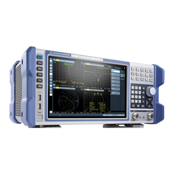
® Instrument tour R&S Front panel view Instrument tour Front panel view This chapter describes the front panel, including all function keys and connectors. Figure 4-1: Front panel view 1 = Power key 2 = USB (2.0) connectors 3 = System keys 4 = Touchscreen 5 = Function keys 6 = Keypad... - Page 34 ® Instrument tour R&S Front panel view Figure 4-2: Touchscreen elements 1 = Toolbar with standard application functions, e.g. print, save/open file etc. 2 = Tabs for individual channel setups 3 = Softtool panel (a.k.a. softkey bar) 4 = Window title bar with diagram-specific (trace) information 5 = Measurement results (diagram) area 6 = Channel list 7 = Diagram footer with diagram-specific information...
- Page 35 ® Instrument tour R&S Front panel view ● Zooming into a diagram ● Selecting a new evaluation method ● Scrolling through a result list or table ● Saving or printing results and settings To imitate a right-click by mouse using the touchscreen, for example to open a context-sensitive menu for a specific item, press the screen for about 1 second.
- Page 36 ® Instrument tour R&S Front panel view Table 4-1: System keys System key Assigned functions [Preset] Resets the instrument to the default state. [Setup] Provides basic instrument configuration functions, e.g.: ● Reference frequency (external/internal) ● Date, time, display configuration ● LAN interface ●...
- Page 37 ® Instrument tour R&S Front panel view Table 4-2: Function keys Function key Assigned functions VNA mode SA mode [Freq] Defines the sweep range. Sets the center frequency and the start and stop frequencies for the frequency range under considera- tion.
- Page 38 ® Instrument tour R&S Front panel view Function key Assigned functions VNA mode SA mode [Meas] Selects the quantities to be measured and displayed. [Format] Selects the trace format (dB magni- Configure measurements and data tude, Smith, etc.). input and output [Config] [Display Lines] Configures display lines and limit lines.
- Page 39 ® Instrument tour R&S Front panel view Type of key Description If an alphanumeric entry has already been started, this key dele- tes the character to the left of the cursor. (BACKSPACE) ● [ENTER] Concludes the entry of dimensionless entries. The new value is accepted.
- Page 40 ® Instrument tour R&S Front panel view Arrow Up/Arrow Down Keys The <arrow up> or <arrow down> keys do the following: ● For numeric entries: increments (Arrow Up) or decrements (Arrow Down) the instrument parameter at a defined step width ●...
-
Page 41: Rear Panel View
® Instrument tour R&S Rear panel view Maximum input levels The maximum input levels at all test ports according to the front panel label- ing or the data sheet must not be exceeded. In addition, the maximum input voltages of the other input connectors at the rear panel must not be exceeded. - Page 42 ® Instrument tour R&S Rear panel view 14 15 Figure 4-3: Rear panel view R&S ZNL 1+2 = Removable, rechargeable Li-ion batteries = DC power supply = AC power supply connection and main power switch with fuse = GPIB (IEC 625) interface = Reference clock connectors = Trigger input connector = "DVI"...
- Page 43 ® Instrument tour R&S Rear panel view Position 1: The instrument is in operation. Position O: The entire instrument is disconnected from the AC power supply. For details, refer to "Connecting to power" on page 7 and Chapter 3.5, "Connect- ing to power", on page 18.
- Page 44 ® Instrument tour R&S Rear panel view The optional GPIB interface is in compliance with IEEE488 and SCPI. A computer for remote control can be connected via this interface. To set up the connection, a shielded cable is recommended. 4.2.4 Ref.
- Page 45 ® Instrument tour R&S Rear panel view Conventional noise sources require a voltage of +28 V to be switched on and 0 V to be switched off. The output supports a maximum load of 100 mA. 4.2.7 IF/Video Output The female BNC connector can be used for various outputs in the Spectrum application: ●...
- Page 46 ® Instrument tour R&S Rear panel view This connector is provided by the "Additional Interfaces" option R&S FPL1- Short-circuit hazard Always observe the designated pin assignment. A short-circuit can damage the port. 4.2.9 Headphones connector The Spectrum mode provides demodulators for AM, FM and PM signals, which can be routed to the headphone connector.
- Page 47 ® Instrument tour R&S Rear panel view This connector is provided by the "Additional Interfaces" option R&S FPL1- 4.2.11 The rear panel provides two additional female USB (3.0 standard) connectors to connect external devices (see also Chapter 4.2.11, "USB", on page 47). 4.2.12 LAN The R&S ZNL is equipped with a 1 GBit Ethernet IEEE 802.3u network interface with Auto-MDI(X) functionality.
- Page 48 ® Instrument tour R&S Rear panel view The serial number is used to define the default instrument name, which is: <Type><variant>-<serial_number> For example, ZNL3-123456. The instrument name is required to establish a connection to the instrument in a LAN. Getting Started 1323.2867.02 ─ 18...
-
Page 49: Trying Out The Instrument
® Trying out the instrument R&S Performing measurements Trying out the instrument This chapter introduces the most important functions and settings of the R&S ZNL step by step. The complete description of the functionality and its usage is given in the R&S ZNL User Manual. Basic instrument operation is described in Chap- ter 6, "Operating the instrument",... - Page 50 ® Trying out the instrument R&S Performing measurements Measurement stages in the wizard The individual dialogs of the "S-Parameter Wizard" correspond to the typical stages of any measurement: 1. Select the test setup. 2. Define port impedances. 3. Select the measurement parameters and the diagrams. 4.
- Page 51 ® Trying out the instrument R&S Performing measurements 1. Connect the DUT between test ports 1 and 2 of the network analyzer as shown above. 2. Use the [Preset] key to restore a well-defined instrument state. The analyzer is now set to its default state. The default measured quantity is the transmission S-parameter S Select [Trace] and use the control elements in the "Traces"...
- Page 52 ® Trying out the instrument R&S Performing measurements The R&S ZNL automatically adjusts its internal source and receiver to the selected measured quantities: For an S measurement, a stimulus signal (termed a ) is transmitted at the analyzer port no. 1; the transmitted wave (termed ) is measured at port 2.
- Page 53 ® Trying out the instrument R&S Performing measurements 5.1.1.3 Calibrating the instrument Calibration (system error correction) is the process of eliminating systematic, reproducible errors from the measurement results. E.g., in the current test setup, the connecting cables between the analyzer ports and the DUT introduce an attenuation and a phase shift of the waves.
- Page 54 ® Trying out the instrument R&S Performing measurements 4. Select "Next" to proceed to the next page of the "Calibration Setting" wizard. 5. Select the test port connector type and gender (here: N 50 Ω, female, corre- sponding to a male Through standard), and the calibration kit (here: R&S ZV- Z121).
- Page 55 ® Trying out the instrument R&S Performing measurements 7. The calibration dock widget indicates the standard measurements that make up a "Trans Norm" calibration. Select "Through (mm)" to initiate the measurement of the connected Through standard. Measuring the isolation between ports 1 and 2 is optional. Skip it for now.
- Page 56 ® Trying out the instrument R&S Performing measurements 5.1.1.4 Evaluating data The analyzer provides various tools to optimize the display and analyze the mea- surement data. For instance, you can use markers to determine maxima and min- ima on the trace, and change the display format to obtain information about the group delay of the transmitted wave.
- Page 57 ® Trying out the instrument R&S Performing measurements Refer to the information on trace formats in the help system or in the user manual to learn more about the diagram properties. 5.1.2 Reflection S-parameter measurement In a reflection measurement, the analyzer transmits a stimulus signal to the input port of the device under test (DUT) and measures the reflected wave.
- Page 58 ® Trying out the instrument R&S Performing measurements You can also use the basic transmission test setup, e.g. if you want to mea- sure reflection and transmission parameters in parallel. ● The analyzer provides special calibration types for reflection measurements. Use the calibration wizard and select an appropriate type.
-
Page 59: Zooming Into The Display
® Trying out the instrument R&S Zooming into the display Zooming into the display To analyze the areas around the peak levels in more detail, we will zoom into a peak. 1. Tap the "Multiple Zoom" icon in the toolbar. The icon is highlighted to indicate that zoom mode is active. -
Page 60: Saving Settings
® Trying out the instrument R&S Saving settings Figure 5-2: Zoomed display around a peak Saving settings To restore the results of our measurements later, we will store the instrument set- tings to a file. To save the instrument settings to a file 1. - Page 61 ® Trying out the instrument R&S Saving settings Keep the default "File Type" setting "Instrument with all Channel Setups" to store the configuration of all channel setups. Figure 5-3: Saving the instrument settings to a file 4. Tap the "Save" button. The file MyMultiViewSetup.dfl is stored in the default directory C:\Users\Public\Documents\Rohde-Schwarz\ZNL\Save.
-
Page 62: Printing And Saving Results
® Trying out the instrument R&S Printing and saving results 2. Tap the "Load" icon in the toolbar. 3. In the "Load" dialog box, select the MyMultiViewSetup.dfl file in the default directory C:\Users\Public\Documents\Rohde-Schwarz\ZNL\Save. 4. Tap the "Load" button. All instrument settings are restored and the display should resemble the instrument display right before the settings were stored. -
Page 63: Activating Additional Channel Setups
® Trying out the instrument R&S Activating additional channel setups 2. In the "Save Hardcopy as " > "Portable Network Graphics (PNG)" dialog box, enter a file name, e.g. MyMultiViewDisplay. The screenshot is stored to MyMultiViewDisplay.png. Activating additional channel setups The R&S ZNL features multiple channel setups, i.e. - Page 64 ® Trying out the instrument R&S Activating additional channel setups 3. Change the frequency range for this measurement: Set the center frequency to 500 MHz and the span to 1 GHz. 4. Press the [Mode] key on the front panel. 5.
- Page 65 ® Trying out the instrument R&S Activating additional channel setups d) Drag the "Real/Imag (I/Q)" icon from the evaluation bar to the SmartGrid. Figure 5-5: Inserting a Real/Imag diagram for I/Q analysis e) Close the SmartGrid mode. The "IQ Analyzer" channel setup displays the real and imaginary signal parts in separate windows.
-
Page 66: Trying Out Spectrum Mode
® Trying out the instrument R&S Trying out spectrum mode Figure 5-6: The "MultiView" tab Trying out spectrum mode If the spectrum analysis option R&S ZNLxx-B1 is installed, you can use the instru- ment for Spectrum measurements. The following chapters describe some basic tasks in spectrum mode. -
Page 67: Measuring A Basic Signal
® Trying out the instrument R&S Trying out spectrum mode 5.6.1 Measuring a basic signal We will start out by measuring a simple sinus wave, using the internal calibration signal as the input. To display the internal 50 MHz calibration signal 1. - Page 68 ® Trying out the instrument R&S Trying out spectrum mode Figure 5-7: Calibration signal as RF input Instrument warmup time Note that the instrument requires an initial warmup time after switching it on. A message in the status bar ("Instrument warming up...") indicates that the operating temperature has not yet been reached.
-
Page 69: Displaying A Spectrogram
® Trying out the instrument R&S Trying out spectrum mode b) Close the "Frequency" dialog box. 3. Set the reference level to -25 dBm: a) In the configuration "Overview", tap the "Amplitude" button. b) In the "Value" field of the "Amplitude" dialog box, enter -25 dBm. The display of the calibration signal is now improved. - Page 70 ® Trying out the instrument R&S Trying out spectrum mode The SmartGrid mode is activated, and the evaluation bar with the available evaluation methods is displayed. Drag the "Spectrogram" icon from the evaluation bar to the diagram area. The blue area indicates that the new diagram would replace the previous spectrum display.
-
Page 71: Setting And Moving A Marker
® Trying out the instrument R&S Trying out spectrum mode Figure 5-10: Spectrogram of the calibration signal 5.6.3 Setting and moving a marker Markers are useful to determine the position of particular effects in the trace. The most common use is to determine a peak, which is the default setting when you activate a marker. - Page 72 ® Trying out the instrument R&S Trying out spectrum mode Marker 1 is activated and automatically set to the maximum of trace 1. The marker position and value is indicated in the diagram area as M1[1]. 6. Now you can move the marker by tapping and dragging it to a different posi- tion.
-
Page 73: Displaying A Marker Peak List
® Trying out the instrument R&S Trying out spectrum mode 5.6.4 Displaying a marker peak list The marker peak list determines the frequencies and levels of peaks in the spec- trum automatically. We will display a marker peak list for the Spectrum 2 channel setup. -
Page 74: Performing Sequential Measurements
® Trying out the instrument R&S Performing sequential measurements b) Tap the "Marker Config" softkey in the "Marker" menu. c) Tap the "Search" tab in the "Marker" dialog box. d) In the "Threshold" field, enter -68 dBm. e) Tap the "State" box for "Threshold" to activate its use. Only peaks that are larger than -68 dBm will be included in the peak list. - Page 75 ® Trying out the instrument R&S Performing sequential measurements 2. Toggle the "Sequencer" softkey in the "Sequencer" menu to "On". A continuous sequence is started, i.e. each channel setup measurement is performed one after the other until the Sequencer is stopped. Figure 5-12: "MultiView"...
-
Page 76: Operating The Instrument
® Operating the instrument R&S Understanding the Display Information (VNA Mode) Operating the instrument This chapter provides an overview on how to work with the R&S ZNL. Remote control In addition to working with the R&S ZNL interactively, located directly at the instrument, it is also possible to operate and control it from a remote PC. - Page 77 ® Operating the instrument R&S Understanding the Display Information (VNA Mode) 1 = Window title bar with measurement-specific (trace) information 2 = Diagram area with marker information 3 = Diagram footer with diagram-specific information Window title bar For each parameter diagram, a window is displayed with the following information in the title bar: 1 = Trace name 2 = Measured parameter...
-
Page 78: Accessing The Functionality
® Operating the instrument R&S Accessing the functionality Diagram footer For each parameter diagram, a window is displayed with the following information in the footer: 1 = Channel 2 = Center frequency 3 = Power level 4 = Measurement bandwidth 5 = Span Accessing the functionality All tasks necessary to operate the instrument can be performed using this user... - Page 79 ® Operating the instrument R&S Accessing the functionality 6.2.1 Toolbar functions Standard functions can be performed via the icons in the toolbar at the top of the screen. You can hide the toolbar display, e.g. when using remote control, to enlarge the display area for the measurement results ("Setup"...
- Page 80 ® Operating the instrument R&S Accessing the functionality The undo function is useful, for example, if you are performing a zero span mea- surement with several markers and a limit line defined and accidentally select a different measurement. In this case, many settings would be lost. However, if you press [UNDO] immediately afterwards, the previous status is retrieved, i.e.
- Page 81 ® Operating the instrument R&S Accessing the functionality Frequency lock Frequency does not change when you turn the rotary knob. Only applies to the frequency. You can still change other parameters with the rotary knob. Windows Displays the Windows "Start" menu and task bar. "To access the "Start"...
- Page 82 ® Operating the instrument R&S Accessing the functionality If you close the softkey bar using its close icon, it is automatically reopened the next time a function key is pressed. You can change this behavior in the "User Interface" tab of the "VNA Setup" dialog. Some controls on the softtool tabs allow you to read and modify settings (e.g.
-
Page 83: Entering Data
® Operating the instrument R&S Entering data 6.2.4 On-screen keyboard The on-screen keyboard is an additional means of interacting with the instrument without having to connect an external keyboard. The on-screen keyboard display can be switched on and off as desired using the "On-Screen Keyboard"... - Page 84 ® Operating the instrument R&S Entering data Transparent dialog boxes You can change the transparency of the dialog boxes to see the results in the windows behind the dialog box. Thus, you can see the effects that the changes you make to the settings have on the results immediately. To change the transparency, select the transparency icon at the top of the dialog box.
-
Page 85: Touchscreen Gestures
® Operating the instrument R&S Touchscreen gestures Correcting an entry 1. Using the arrow keys, move the cursor to the right of the entry you want to delete. 2. Press the [Backspace] key. The entry to the left of the cursor is deleted. 3. - Page 86 ® Operating the instrument R&S Touchscreen gestures Double-tapping Tap the screen twice, in quick succession. Double-tap a diagram or the window title bar to maximize a window in the display, or to restore the original size. Dragging Move your finger from one position to another on the display, keeping your finger on the display the whole time.
- Page 87 ® Operating the instrument R&S Touchscreen gestures Figure 6-4: Pinching Figure 6-5: Spreading Touch gestures in diagrams change measurement settings When you change the display using touch gestures, the corresponding mea- surement settings are adapted. This is different to selecting an area on the screen in zoom mode, where merely the resolution of the displayed trace points is changed temporarily (graphical zoom).
-
Page 88: Getting Help
® Operating the instrument R&S Getting help Mouse operation Touch operation Drag-&-drop (= click and hold, then drag and Touch, then drag and release release) n.a. (Change hardware settings) Spread and pinch two fingers Mouse wheel to scroll up or down Swipe Dragging scrollbars to scroll up or down, left or Swipe... - Page 89 ® Operating the instrument R&S Getting help The "Help" dialog box "View" tab is displayed. A topic containing information about the focused screen element is displayed. If no context-specific help topic is available, a more general topic or the "Con- tent"...
-
Page 90: Customer Support
® Customer support R&S Collecting information for support Customer support Collecting information for support If problems occur, the instrument generates error messages which in most cases will be sufficient for you to detect the cause of an error and find a remedy. Error messages are described in the "Troubleshooting"... - Page 91 ® Customer support R&S Collecting information for support To collect the support information 1. Press the [Setup] key. 2. Select "Service" > "R&S Support" and then "Create R&S Support Informa- tion" . For example C:\Program Files\Rohde-Schwarz\Vector Network Analyzer\ZNL\ user\ZNL3__20160803_145113.zip To create windows event log files 1.
-
Page 92: Contacting Customer Support
® Customer support R&S Contacting customer support 5. Enter a file name and select "Save" Collect the error information and attach it to an email in which you describe the problem. Send the email to the customer support address for your region as listed Chapter 7.2, "Contacting customer support", on page 92. -
Page 93: Index
® Index R&S Index Alphanumeric parameters ....... 84 Entering data ........... 83 Application cards ........13 Error log ...........90 Application notes ........13 Evaluation Arrow keys ..........40 Trying out ..........69 Aux. Port Evaluation of data ........56 Connector ........... 45 External monitor Connectors ......... - Page 94 ® Index R&S Keyboard Printing On-screen ........... 83 Trying out ..........62 Keypad Overview ..........38 Rear panel Overview ..........41 Ref. In Connector ........... 47 Connector ........... 44 Loading Ref. Out Trying out ..........61 Connector ........... 44 Reflection measurement (example) ..57 Release notes .........
- Page 95 ® Index R&S Connector ........... 47 Connectors ......... 35 White papers ........... 13 Windows Dialog boxes ........84 Windows Access ..........27 Wizard ............. 49 Zoom Graphical ..........87 Measurement ........87 Zooming Trying out ..........59 Getting Started 1323.2867.02 ─ 18...
Need help?
Do you have a question about the ZNL6-COM and is the answer not in the manual?
Questions and answers