Rohde & Schwarz ZNB Getting Started
Vector network analyzers
Hide thumbs
Also See for ZNB:
- Application note (23 pages) ,
- User manual (1498 pages) ,
- Getting started (81 pages)
Table of Contents
Advertisement
Quick Links
Advertisement
Table of Contents

Related Manuals for Rohde & Schwarz ZNB


Summary of Contents for Rohde & Schwarz ZNB
- Page 1 ® R&S ZNB/ZNBT Vector Network Analyzers Getting Started (=@0Ì2) 1316006202...
- Page 2 Subject to change – Data without tolerance limits is not binding. ® R&S is a registered trademark of Rohde & Schwarz GmbH & Co. KG. Trade names are trademarks of the owners. ® 1316.0062.02 | Version 26 | R&S ZNB/ZNBT ® Throughout this guide R&S is abbreviated as R&S.
- Page 3 Safety Instructions Instrucciones de seguridad Sicherheitshinweise Consignes de sécurité Risk of injury and instrument damage The instrument must be used in an appropriate manner to prevent electric shock, fire, personal injury or instrument damage. ● Do not open the instrument casing. ●...
- Page 4 Gefahr von Verletzungen und Schäden am Gerät Betreiben Sie das Gerät immer ordnungsgemäß, um elektrischen Schlag, Brand, Verletzungen von Personen oder Geräteschäden zu verhindern. ● Öffnen Sie das Gerätegehäuse nicht. ● Lesen und beachten Sie die "Grundlegenden Sicherheitshinweise", die als gedruckte Broschüre dem Gerät beiliegen. ●...
-
Page 5: Table Of Contents
® Contents R&S ZNB/ZNBT Contents 1 Preface....................7 For Your Safety......................7 Documentation Overview..................... 7 1.2.1 Getting Started Manual....................7 1.2.2 User Manual and Help....................8 1.2.3 Service Manual....................... 8 1.2.4 Instrument Security Procedures..................8 1.2.5 Basic Safety Instructions....................8 1.2.6 Data Sheets and Brochures.................... 8 1.2.7... - Page 6 2.12.1 Assigning an IP Address....................20 2.12.2 Remote Desktop Connection..................23 ® 2.12.3 Windows Firewall Settings...................23 3 Instrument Tour..................25 Front Panel R&S ZNB....................25 3.1.1 Touchscreen........................26 3.1.2 Function Keys....................... 26 3.1.3 Data Entry Keys......................27 3.1.4 Rotary Knob........................28 3.1.5 Navigation Keys......................
- Page 7 ® Contents R&S ZNB/ZNBT 4.4.2 Adding New Markers.....................52 4.4.3 Deleting Display Elements.................... 53 4.4.4 Using Drag and Drop....................54 Entering Data.......................54 4.5.1 Using Front Panel Keys....................55 4.5.2 Using the Numeric Editor....................56 4.5.3 Using the Analyzer's On-Screen Keyboard..............56 ®...
-
Page 8: Getting Started 1316.0062.02 ─ 26
® Contents R&S ZNB/ZNBT Replacing Fuses......................77 8 Obtaining Technical Support.............. 78 Index......................79 Getting Started 1316.0062.02 ─ 26... -
Page 9: Preface
● https://www.rohde-schwarz.com/manual/ZNBT 1.2.1 Getting Started Manual Introduces the R&S ZNB/ZNBT and describes how to set up and start working with the product. Includes basic operations, typical measurement examples, and general infor- mation, e.g. safety instructions, etc. A printed version is delivered with the instrument. A PDF version is available for down- load on the Internet. -
Page 10: User Manual And Help
Includes the contents of the getting started manual. The contents of the user manual is available as help in the R&S ZNB/ZNBT. The help offers quick, context-sensitive access to the complete information for the instrument and its firmware. -
Page 11: Release Notes And Open Source Acknowledgment (Osa)
® Preface R&S ZNB/ZNBT Conventions Used in the Documentation 1.2.7 Release Notes and Open Source Acknowledgment (OSA) The release notes list new features, improvements and known issues of the current firmware version, and describe the firmware installation. The open source acknowledgment document provides verbatim license texts of the used open source software. -
Page 12: Conventions For Procedure Descriptions
® Preface R&S ZNB/ZNBT Conventions Used in the Documentation 1.3.2 Conventions for Procedure Descriptions When operating the instrument, several alternative methods may be available to per- form the same task. In this case, the procedure using the touchscreen is described. -
Page 13: Putting The Analyzer Into Operation
® Putting the Analyzer into Operation R&S ZNB/ZNBT Unpacking and Checking the Instrument 2 Putting the Analyzer into Operation This section describes the basic steps to be taken when setting up the analyzer for the first time. Simple measurement examples are provided in Chapter 5, "Performing Measure-... -
Page 14: Positioning The Instrument
® Putting the Analyzer into Operation R&S ZNB/ZNBT Bench Top Operation Packing material Retain the original packing material. If the instrument needs to be transported or ship- ped later, you can use the material to protect the control elements and connectors. -
Page 15: Operation In A 19" Rack
The feet can break if they are overloaded. The overall load on the folded-out feet must not exceed 500 N. 2.4 Operation in a 19" Rack The R&S ZNB/ZNBT can be mounted in 19" racks using the adapter R&S ZZA-KN5 (order number 1175.3040.00). Proceed according to the mounting instructions supplied with the rack adapter. -
Page 16: Connecting The Analyzer To The Ac Supply
7.3, "Replacing Fuses", on page 77. There are no such fuses on the R&S ZNB. 2.7 Starting the Analyzer and Shutting Down The AC power switch is located in the upper part of the rear panel, together with the mains connector and the fuse drawer (R&S ZNBT only;... -
Page 17: Standby And Ready State
2.8 Standby and Ready State R&S ZNB: The standby toggle key is located in the bottom left corner of the front panel. In standby state, the right, amber LED is on, in ready state, the left, green LED is on. -
Page 18: Connecting External Accessories
USB. For the R&S ZNBT, external monitor and mouse are required for local operation. The R&S ZNB can be fully controlled by tapping the touchscreen and front panel keys. 2.9.1 Connecting a Monitor A standard monitor can be connected to the DVI-D connector of the R&S ZNB/ZNBT. -
Page 19: Connecting A Keyboard
Start menu to configure the keyboard properties. To access Windows ® , press the Windows key on the front panel (R&S ZNB only) or on the external keyboard. 2.9.3 Connecting a Mouse A USB mouse can be connected to any of the USB connectors. After being auto-detec- ted by the operating system, it can safely be disconnected and reconnected even dur- ing measurements. -
Page 20: Connecting A Lan Cable
Minimizing the VNA Application ® To access Windows , press the Windows key on the front panel (R&S ZNB only) or on the external keyboard. You can load updated and improved driver versions or new drivers from an installation disk, USB memory stick or another external storage medium. Alternatively, if the ana- lyzer is integrated in a network, you can install driver data stored in a network directory. -
Page 21: Changing The Screen Resolution (R&S Znbt)
® Putting the Analyzer into Operation R&S ZNB/ZNBT Changing the Screen Resolution (R&S ZNBT) To exit the default full-screen mode of the VNA application, deselect SYSTEM > [DIS- PLAY] > "View Bar" > "Title Bar Task Bar". Then use the standard Windows ®... -
Page 22: Remote Operation In A Lan
® Putting the Analyzer into Operation R&S ZNB/ZNBT Remote Operation in a LAN 3. Click the rectangular button rightmost on the task bar to show the Windows desk- top. 4. Right-click the Windows desktop and select "Screen resolution" from the context menu 5. - Page 23 DNS domain and the IP addresses of the DNS and WINS servers on your network. 2. For the R&S ZNBT connect an external monitor, keyboard and mouse. 3. Press the Windows key in the SYSTEM keypad (R&S ZNB only) or on an external keyboard to access Windows ®...
- Page 24 ® Putting the Analyzer into Operation R&S ZNB/ZNBT Remote Operation in a LAN Figure 2-1: Windows 7 User Account Control dialog 6. In the "Local Area Connection Properties" dialog opened, select "Internet Protocol Version 4 (TCP/IPv4) > Properties" and enter the IP address information.
-
Page 25: Remote Desktop Connection
A firewall protects an instrument by preventing unauthorized users from gaining access to it through a network. In the default configuration of the R&S ZNB/ZNBT the firewall is enabled. A remote desktop connection does not require any changes in the firewall settings. - Page 26 ® Putting the Analyzer into Operation R&S ZNB/ZNBT Remote Operation in a LAN Some actions require a different firewall configuration, e.g.: ● To transfer data with other hosts in the LAN, you have to allow "File and Printer Sharing". To change the firewall settings, proceed as follows: ®...
-
Page 27: Instrument Tour
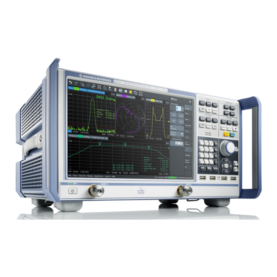
3.1 Front Panel R&S ZNB The front panel of a R&S ZNB consists of the touchscreen with the diagrams and soft- tool panels (left side), the hardkey area (right side) and the test port area below. Brief explanations on the controls and connectors, the hardkey area and the rear panel can be found on the next pages. -
Page 28: Touchscreen
® Instrument Tour R&S ZNB/ZNBT Front Panel R&S ZNB 3.1.1 Touchscreen The analyzer is equipped with a 12.1'' XGA color touchscreen. The touchscreen pres- ents all measurement results, mostly in the form of diagrams. Besides, all instrument functions can be accessed and operated by tapping the control elements on the touch- screen. -
Page 29: Data Entry Keys
® Instrument Tour R&S ZNB/ZNBT Front Panel R&S ZNB The CHANNEL keys give access to the hardware-related (channel) settings. ● The [POWER BW AVG] settings define the power of the internal signal source, the IF bandwidth, and the sweep average. -
Page 30: Rotary Knob
® Instrument Tour R&S ZNB/ZNBT Front Panel R&S ZNB ● The function of the four unit keys depends on the data type of the active input field; Chapter 4.5, "Entering Data", on page 54. – In numeric input fields, the G/n, M/μ, k/m or x1 keys multiply the entered value... -
Page 31: Standby Key
Shut down the instrument; see Chapter 2.7, "Starting the Analyzer and Shutting Down", on page 14. 3.1.7 Front Panel Connectors The test ports and four USB connectors are located on the front panel of the R&S ZNB. 3.1.7.1 Test Ports Numbered connectors: ●... -
Page 32: Front Panel R&S Znbt
® Instrument Tour R&S ZNB/ZNBT Front Panel R&S ZNBT Maximum input levels The maximum input levels at all test ports according to the front panel labeling or the data sheet must not be exceeded. In addition, the maximum input voltages of the other input connectors at the rear panel must not be exceeded. -
Page 33: Test Ports
® Instrument Tour R&S ZNB/ZNBT Front Panel R&S ZNBT Figure 3-2: Front view of R&S ZNBT8 (fully equipped with the maximum 24 ports) Instrument damage caused by cleaning agents Cleaning agents contain substances such as solvents (thinners, acetone, etc.), acids, bases, or other substances. -
Page 34: Administrative Area
® Instrument Tour R&S ZNB/ZNBT Front Panel R&S ZNBT Maximum input levels The maximum input levels at all test ports according to the front panel labeling or the data sheet must not be exceeded. In addition, the maximum input voltages of the other input connectors at the rear panel must not be exceeded. -
Page 35: Rear Panel R&S Znb
Above the standby toggle switch some LEDs indicate various status information: ● [ERR]: operation state; if an error occurs, the LED lights up red; for more informa- tion on errors and troubleshooting see the R&S ZNB/ZNBT User Manual ● [LAN]: LAN error occurred ●... - Page 36 IN / EXT TRIG REF OUT BNC output for the internal reference frequency of the R&S ZNB. Use this connector to synchronize other instruments to the analyzer. REF IN BNC input for an external reference frequency. Use this connector to synchronize the R&S ZNB to another device.
-
Page 37: Rear Panel R&S Znbt
"System Power Management Interface Specification". – 10 General Purpose Input/Output (GPIO) pins. Device Option R&S ZNB-B12 "Device Control" provides a PCIe and a Direct Control con- Control nector. The Direct Control interface enables direct connections between the VNA measure- ment bus and one or more extension devices, such as: ●... - Page 38 ® Instrument Tour R&S ZNB/ZNBT Rear Panel R&S ZNBT Figure 3-4: R&S ZNBT20 rear view Table 3-3: Rear panel connectors available on all instruments Index Label Description (Power Power on/off switch, see Chapter 2.7, "Starting the Analyzer and Shutting Down",...
- Page 39 ® Instrument Tour R&S ZNB/ZNBT Rear Panel R&S ZNBT Index Label Description REF OUT BNC output for the internal reference frequency of the R&S ZNBT. Use this connec- tor to synchronize other instruments to the analyzer. REF IN BNC input for an external reference frequency. Use this connector to synchronize the R&S ZNBT to another device.
-
Page 40: Operating The Instrument
Manual and remote control of the instrument In contrast to the R&S ZNB, the R&S ZNBT is primarily intended to be remote-control- led via the GPIB or LAN interface (see chapter 'Remote Control' in the user manual). - Page 41 For example, you can show/hide the on-screen hardkey panel by selecting/deselecting "Display" > "View Bar" > "Hard Key Panel On" from the main menu. The following table shows possible touchscreen operations (R&S ZNB only) with the corresponding mouse operations. Touchscreen...
- Page 42 ® Operating the Instrument R&S ZNB/ZNBT Manual Operation 2. Activate the desired softtool tab, e.g. "Z←Sij". 3. Select a control element, e.g. "Z←S11". The diagram immediately reflects your selection. The active trace shows the mea- surement results for the selected measured quantity.
- Page 43 ® Operating the Instrument R&S ZNB/ZNBT Manual Operation Using the menu bar The menu bar at the bottom of the application screen provides alternative access to all instrument functions. To repeat the measured quantity selection described above, ► Select TRACE – [MEAS] > "Z←Sij" > "Z←S11".
- Page 44 ® Operating the Instrument R&S ZNB/ZNBT Manual Operation 2. Select "S-Parameter" to open the "Meas" > "S-Params" softtool tab. 3. Select "Z←Sij" > "Z←S11". Getting Started 1316.0062.02 ─ 26...
-
Page 45: Control Elements Of The Application Window
® Operating the Instrument R&S ZNB/ZNBT Control Elements of the Application Window 4.2 Control Elements of the Application Window The application window of the analyzer provides all control elements for the measure- ments and contains the diagrams for the results. There are several alternative ways for accessing an instrument function: ●... -
Page 46: Title Bar
® Operating the Instrument R&S ZNB/ZNBT Control Elements of the Application Window These methods are described in more detail in the following sections. 4.2.1 Title Bar By default, the analyzer GUI is shown in full screen mode, covering the whole screen and hiding the Windows taskbar. -
Page 47: Softtools
4.2.3 Softtools Softtools display groups of related settings as a tabbed panel. They can be opened via function keys on the front panel (R&S ZNB only) or the on-screen "Hard Key" panel, or via menu bar and context menu items. -
Page 48: Menu Bar
(R&S ZNB only) or a mouse. A short tap (left mouse click) expands a menu or sub- menu. If a menu command has no submenu assigned, a short tap (left mouse click) opens a dialog or directly activates the menu command. -
Page 49: Hardkey Panel
The (virtual) "Hard Key" panel provides on-screen access to the function keys (plus the [UNDO] and [REDO] key) that are available at the front panel of a R&S ZNB. Most of the function keys open a related softtool. For a short description, refer to section Chap- ter 3.1.2, "Function... -
Page 50: Status Bar
The "Hard Key" panel is particularly useful if the analyzer is controlled from an external monitor or Remote Desktop. For the R&S ZNB, it is hidden by default, for the R&S ZNBT it is visible by default. You can display the "Hard Key" panel using one of the following methods: ●... -
Page 51: Working With Dialogs
(See the R&S ZNB/ZNBT User Manual) ● the current date and time Figure 4-3: R&S ZNB/ZNBT with redefined physical ports Figure 4-4: R&S ZNB/ZNBT with switch matrix The progress bar shows a moving color gradient if the current sweep is too fast to be monitored, e.g. - Page 52 ® Operating the Instrument R&S ZNB/ZNBT Working with Dialogs All dialogs are operated in a similar way. ● To open a dialog, select a softtool button with three dots appearing in its label (e.g. "Start... (Manual)"). ● The title bar of each dialog contains some convenience functions: –...
-
Page 53: Handling Diagrams, Traces, And Markers
For further reference Refer to chapter "Concepts and Features" in the R&S ZNB/ZNBT Help or in the User Manual to learn more about traces, channels, and screen elements. 4.4.1 Adding New Traces and Diagrams A new trace is required if you want to measure and display an additional quantity. -
Page 54: Adding New Markers
3. In the dialog box that is opened when you release the "New Trace" icon, select the S-parameter to be measured. For a four-port analyzer: The R&S ZNB/ZNBT generates a new trace for the selected S-parameter. Alternative control elements To measure a different quantity, select TRACE – [MEAS]. Drag and drop a softkey rep- resenting a measured quantity to create a trace. -
Page 55: Deleting Display Elements
® Operating the Instrument R&S ZNB/ZNBT Handling Diagrams, Traces, and Markers marker position. The response value varies as the analyzer continues performing sweeps. Active trace, alternative control elements The trace line of the active trace in the upper part of the diagram is highlighted. If the diagram contains several traces, first activate the target trace, then add the marker. -
Page 56: Using Drag And Drop
"Undo" toolbar icon. 4.4.4 Using Drag and Drop You can drag and drop many of the R&S ZNB/ZNBT's control and display elements to change their size and position. The drag and drop functionality is often more conven- ient to use than the equivalent buttons of the softtool panels. The following table gives an overview. -
Page 57: Using Front Panel Keys
ZNB/ZNBT Entering Data 4.5.1 Using Front Panel Keys On a R&S ZNB you can use the keys in the DATA ENTRY keypad to enter numbers, units, and characters. To enter a numeric value: 1. Select a numeric data input field to activate it. -
Page 58: Using The Numeric Editor
® Operating the Instrument R&S ZNB/ZNBT Entering Data ® ● Chapter 4.5.4, "Using the Windows On-Screen Keyboard", on page 57 4.5.2 Using the Numeric Editor The "Numeric Editor" is a tool for convenient entry and modification of numeric values. It is available for all numeric input fields in the analyzer GUI. -
Page 59: Using The Windows ® On-Screen Keyboard
® Operating the Instrument R&S ZNB/ZNBT Entering Data 1. Activate a character data input field in a softtool or a dialog. 2. Double-tap/click the input field to open the on-screen keyboard. 3. Select character buttons to compose the input string. -
Page 60: Scaling Diagrams
® Operating the Instrument R&S ZNB/ZNBT Scaling Diagrams 4.6 Scaling Diagrams The analyzer provides various tools for customizing the diagrams and for setting the sweep range. Choose the method that is most convenient for you. 4.6.1 Using the Graphical Zoom The graphical zoom function magnifies a rectangular portion of the diagram (zoom win- dow) to fill the entire diagram area. -
Page 61: Setting The Sweep Range
® Operating the Instrument R&S ZNB/ZNBT Scaling Diagrams Use the "Zoom Reset" icon to restore the original diagram. Alternatively, you can drag and drop the "Zoom" label from the additional channel info line onto the "Delete" tool- bar button. Alternative settings ●... -
Page 62: Reference Value And Position
® Operating the Instrument R&S ZNB/ZNBT Scaling Diagrams ● Tap and hold (with a mouse: right-click) the "Start" or "Stop" label in the channel list and select "Start Frequency", "Stop Frequency", "Center Frequency", or "Fre- quency Span" from the context menu. -
Page 63: Circular Diagrams
® Operating the Instrument R&S ZNB/ZNBT Scaling Diagrams 4.6.5 Circular Diagrams The radial scale of a circular diagram ("Polar", "Smith" or "Inverted Smith") can be changed with a single linear parameter, the "Ref Value". The reference value defines the radius of the outer circumference. -
Page 64: Enlarging A Diagram
® Operating the Instrument R&S ZNB/ZNBT Scaling Diagrams Set "Start" and "Stop" values in the diagram: 1. Create two normal markers, e.g. the markers "Mkr 1" (default label "M1") and "Mkr 2" (default label "M2"). Chapter 4.4.2, "Adding New Markers", on page 52. - Page 65 ® Operating the Instrument R&S ZNB/ZNBT Scaling Diagrams ● The SYSTEM – [DISPLAY] > "Config" softtool tab defines optional display elements for the interior of the diagrams. Use the context menu of the diagram, the SYSTEM – [DISPLAY] key or the "Display"...
-
Page 66: Performing Measurements
ZNB/ZNBT Transmission S-Parameter Measurement 5 Performing Measurements This chapter takes you through a sample session with a R&S ZNB/ZNBT network ana- lyzer and describes basic operation tasks. Safety considerations Before starting any measurement on your network analyzer, please note the instruc- tions given in Chapter 2, "Putting the Analyzer into... -
Page 67: Connecting The Instrument For Transmission Measurements
To prepare a transmission measurement, you have to connect your DUT (which for simplicity we assume to have appropriate connectors) in-between a pair of analyzer test ports. It is recommended that you preset the R&S ZNB/ZNBT to start from a well- defined instrument state. -
Page 68: Selecting The Sweep Range And Other Parameters
Chapter 4.5.2, "Using the Numeric Editor", on page 56). Tip: If you use the DATA ENTRY keys at the front panel for data entry (R&S ZNB only), type [1][.][7][7] and terminate the entry with the [G/n] key. Refer to Chapter 4.5, "Entering Data",... -
Page 69: Calibrating The Instrument
With a single Through, it is possible to perform a transmission normalization, compen- sating for a frequency-dependent attenuation and phase shift in the signal paths. Due to the R&S ZNB/ZNBT's calibration wizard, calibration is a straightforward, guided process. 1. Replace the DUT by the Through standard of your calibration kit. - Page 70 ® Performing Measurements R&S ZNB/ZNBT Transmission S-Parameter Measurement Tip: For a R&S ZNBT with more than 4 ports, the graphical port representation is replaced by a generic port list. The selection logic is unchanged. 4. Select "Next" to proceed to the next page of the "Calibration Setting" wizard.
-
Page 71: Evaluating Data
Through standard. The similarity of real and expected traces indicates that the Through standard has been properly connected. After the R&S ZNB/ZNBT has completed the calibration sweep and calculated the correction data, the "Apply" button is enabled. -
Page 72: Saving And Printing Data
® Performing Measurements R&S ZNB/ZNBT Transmission S-Parameter Measurement 2. Select TRACE – [MARKER], activate the "Marker Search" softtool tab and activate "Min" search. The marker jumps to the absolute minimum of the curve in the entire sweep range. The marker info field shows the coordinates of the new marker position. -
Page 73: Reflection S-Parameter Measurement
® Performing Measurements R&S ZNB/ZNBT Reflection S-Parameter Measurement 1. Activate the SYSTEM – [FILE] > "Trace Data" softtool tab. 2. In the "Trace Data" softtool tab, select "Export" – "ASCII..." to open the "Export Data - ASCII Files" dialog. 3. In the "Export Data - ASCII Files" dialog: a) Select a file location ("Look in:"). - Page 74 ® Performing Measurements R&S ZNB/ZNBT Reflection S-Parameter Measurement You can also use the basic transmission test setup, e.g. if you want to measure reflection and transmission parameters in parallel. ● The analyzer provides special calibration types for reflection measurements. Use the calibration wizard and select an appropriate type.
- Page 75 ® Performing Measurements R&S ZNB/ZNBT Reflection S-Parameter Measurement Proceed as described in Chapter 2.7, "Starting the Analyzer and Shutting Down", on page 14 to shut down your analyzer. Getting Started 1316.0062.02 ─ 26...
-
Page 76: Administrative Tasks
To switch from one user account to another, log off from Windows and then log on again. The "switch user" functionality is disabled on the R&S ZNB/ZNBT. Getting Started 1316.0062.02 ─ 26... -
Page 77: Firmware Update
® Administrative Tasks R&S ZNB/ZNBT Firmware Update 6.2 Firmware Update Upgrade versions of the analyzer firmware are supplied as single Windows ® installer files (*.msi). Administrator account You need administrator rights to install a new firmware version. See note on "User... -
Page 78: Maintenance
ZNB/ZNBT Cleaning 7 Maintenance The R&S ZNB/ZNBT vector network analyzer does not require any special mainte- nance. For our support center address and a list of useful R&S contact addresses, refer to the "Contact" page at the beginning of the Help system. -
Page 79: Storing And Packing The Instrument
The fuse is screwed in below the AC power switch on the rear panel. For the R&S ZNB, each of the optional "Bias Tee" inputs at the rear panel (labeled PORT BIAS <no>) is protected by a fuse (0.250 A, F IEC60127-2/2, stock no. -
Page 80: Obtaining Technical Support
The instrument generates error messages which are usually sufficient for you to detect the cause of an error and find a remedy. Error message types are described in the R&S ZNB/ZNBT User Manual; refer to section "Error Messages and Troubleshooting". In addition, the system "Info" dialog offers valuable troubleshooting information. This dialog can be opened via the "Info..."... -
Page 81: Index
Firmware update Numeric Editor (dialog) ............. 56 Update ................ 75 Front panel LED controls ............... 33 Mini display ..............32 OCXO Frequency Reference ..........15 R&S ZNB ..............25 R&S ZNBT ..............30 USB ................32 Getting Started 1316.0062.02 ─ 26... - Page 82 STIMULUS ................ 27 R&S ZNB-B81 ............. 35 Storing ................77 R&S ZNBT-B4 ............. 15 Support ................78 Option R&S ZNB-B19 ............34 Sweep range selection ............66 Option R&S ZNBT-B10 ............. 37 Sweep range setting ............59 Option R&S ZNBT-B12 ............. 37 SYSTEM ................
Need help?
Do you have a question about the ZNB and is the answer not in the manual?
Questions and answers