Rohde & Schwarz ZVH4 Operating Manual
Cable and antenna
Hide thumbs
Also See for ZVH4:
- Operating manual (194 pages) ,
- Manual (7 pages) ,
- Operating manual (246 pages)
Table of Contents
Advertisement
Advertisement
Table of Contents

Related Manuals for Rohde & Schwarz ZVH4


Summary of Contents for Rohde & Schwarz ZVH4
-
Page 1: Operating Manual
R&S ® Cable and Antenna Analyzer Operating Manual 1309.6946.12 – 09... - Page 2 The Operating Manual describes the following R&S ZVH models and options ® ● R&S ZVH4 (1309.6800.24) ● R&S ZVH8 (1309.6800.28) ● R&S ZVH-K1 (1309.6823.02) ● R&S ZVH-K9 (1309.6852.02) ● R&S ZVH-K19 (1304.5987.02)) ● R&S ZVH-K14 (1309.7007.02) ● R&S ZVH-K29 (1304.0491.02) ●...
-
Page 3: Basic Safety Instructions
R&S ZVH Basic Safety Instructions Basic Safety Instructions Always read through and comply with the following safety instructions! All plants and locations of the Rohde & Schwarz group of companies make every effort to keep the safety standards of our products up to date and to offer our customers the highest possible degree of safety. - Page 4 R&S ZVH Basic Safety Instructions Observing the safety instructions will help prevent personal injury or damage of any kind caused by dangerous situations. Therefore, carefully read through and adhere to the following safety instructions before and when using the product. It is also absolutely essential to observe the additional safety instructions on personal safety, for example, that appear in relevant parts of the product documentation.
- Page 5 R&S ZVH Basic Safety Instructions 2. Do not place the product on heat-generating devices such as radiators or fan heaters. The ambient temperature must not exceed the maximum temperature specified in the product documentation or in the data sheet. Product overheating can cause electric shock, fire and/or serious personal injury or death.
- Page 6 R&S ZVH Basic Safety Instructions 11. Use suitable overvoltage protection to ensure that no overvoltage (such as that caused by a bolt of lightning) can reach the product. Otherwise, the person operating the product will be exposed to the danger of an electric shock. 12.
- Page 7 R&S ZVH Basic Safety Instructions Repair and service 1. The product may be opened only by authorized, specially trained personnel. Before any work is performed on the product or before the product is opened, it must be disconnected from the AC supply network. Otherwise, personnel will be exposed to the risk of an electric shock.
- Page 8 R&S ZVH Basic Safety Instructions Transport 1. Handles on the products are designed exclusively to enable personnel to transport the product. It is therefore not permissible to use handles to fasten the product to or on transport equipment such as cranes, fork lifts, wagons, etc. The user is responsible for securely fastening the products to or on the means of transport or lifting.
- Page 9 R&S ZVH Informaciones Elementales de Seguridad Informaciones Elementales de Seguridad Es imprescindible leer y observar las siguientes instrucciones e informaciones de seguridad! El principio del grupo de empresas Rohde & Schwarz consiste en tener nuestros productos siempre al día con los estándares de seguridad y de ofrecer a nuestros clientes el máximo grado de seguridad.
- Page 10 R&S ZVH Informaciones Elementales de Seguridad Tener en cuenta las informaciones de seguridad sirve para evitar en lo posible lesiones o daños por peligros de toda clase. Por eso es imprescindible leer detalladamente y comprender por completo las siguientes informaciones de seguridad antes de usar el producto, y respetarlas durante el uso del producto.
- Page 11 R&S ZVH Informaciones Elementales de Seguridad 1. El producto solamente debe ser utilizado según lo indicado por el fabricante referente a la situación y posición de funcionamient. R&S ZVH está protegido contra roción y polvo (modo de protección IP 51). Si no se convino de otra manera, es para los productos Rohde &...
- Page 12 R&S ZVH Informaciones Elementales de Seguridad 7. En las mediciones en circuitos de corriente con una tensión U > 30 V se deberán tomar las medidas apropiadas para impedir cualquier peligro (p. ej. medios de medición adecuados, seguros, limitación de tensión, corte protector, aislamiento etc.).
- Page 13 R&S ZVH Informaciones Elementales de Seguridad 3. Como con todo producto de fabricación industrial no puede quedar excluida en general la posibilidad de que se produzcan alergias provocadas por algunos materiales empleados, los llamados alérgenos (p. ej. el níquel). Si durante el manejo de productos Rohde &...
- Page 14 R&S ZVH Informaciones Elementales de Seguridad 3. Las celdas o baterías no deben cortocircuitarse. Es peligroso almacenar las celdas o baterías en estuches o cajones en cuyo interior puedan cortocircuitarse por contacto recíproco o por contacto con otros materiales conductores. No deben extraerse las celdas o baterías de sus embalajes originales hasta el momento en que vayan a utilizarse.
- Page 15 Customer Support Technical support – where and when you need it For quick, expert help with any Rohde & Schwarz equipment, contact one of our Customer Support Centers. A team of highly qualified engineers provides telephone support and will work with you to find a solution to your query on any aspect of the operation, programming or applications of Rohde &...
-
Page 16: Table Of Contents
R&S ZVH Table of Contents Table of Contents Documentation Overview ..............6 Conventions Used in the Documentation ......... 7 1 Operating the R&S ZVH ..............8 Screen Layout and Elements ..................8 Means of Input ......................9 1.2.1 Using the Alphanumeric Keys ..................10 1.2.2 Confirming and Cancelling Entries ................11 1.2.3... - Page 17 R&S ZVH Table of Contents 2.1.2 Distance to Fault Measurements .................40 2.1.3 1-Port Cable Loss Measurements ................41 2.1.4 Transmission Measurements (R&S ZVH-K39) ............42 2.1.5 Selecting the Measurement Format................43 2.1.6 Calibrating Measurements ...................44 Configuring Cable and Antenna Tests ..............48 2.2.1 Selecting the Cable Model ...................48 2.2.2 Configuring the Horizontal Axis ...................51 2.2.3...
- Page 18 R&S ZVH Table of Contents 4.1.9 Measuring Spurious Emissions .................106 4.1.10 Working with the Spectrogram Result Display (R&S ZVH-K14) ........109 4.1.11 Using Isotropic Antennas ...................120 Configuring Spectrum Measurements ..............122 4.2.1 Configuring the Horizontal Axis .................122 4.2.2 Configuring the Vertical Axis ..................126 4.2.3 Setting Bandwidths ....................131 4.2.4...
- Page 19 R&S ZVH Table of Contents 6.2.2 Measuring the Reflection ...................185 Evaluating the Results ....................187 6.3.1 Selecting the Measurement Format................187 6.3.2 Configuring the Vertical Axis ..................194 6.3.3 Using Markers ......................196 6.3.4 Working with Channel Tables ..................196 6.3.5 Using Limit Lines......................197 6.3.6 Using Trace Mathematics ..................197 Vector Voltmeter (R&S ZVH-K45) ................198 6.4.1...
- Page 20 R&S ZVH Table of Contents 7.3.8 Markers ........................211 Functions of the Network Analyzer (R&S ZVH-K42) ..........212 7.4.1 Measurement Configuration ..................212 7.4.2 Frequency Parameters ....................212 7.4.3 Measurement Format Selection .................212 7.4.4 Amplitude Parameters ....................213 7.4.5 Sweep Configuration ....................213 7.4.6 Trace Functionality.....................213 7.4.7 Limit Lines ........................213 7.4.8...
-
Page 21: Documentation Overview
R&S ZVH Documentation Overview Documentation Overview The user documentation for the R&S ZVH is divided as follows: Quick Start Guide The Quick Start Guide provides basic information on the instrument's functions. It covers the following topics: ● overview of all elements of the front and rear panels ●... -
Page 22: Conventions Used In The Documentation
R&S ZVH Conventions Used in the Documentation Conventions Used in the Documentation The following conventions are used throughout the R&S R&S ZVH Operating Manual: Typographical conventions Convention Description “Graphical user interface elements” All names of graphical user interface elements both on the screen and on the front and rear panels, such as dialog boxes, softkeys, menus, options, buttons etc., are enclosed by quotation marks. -
Page 23: Operating The R&S Zvh
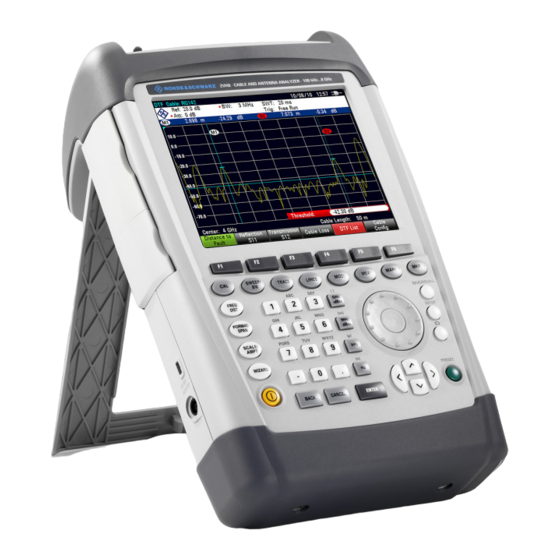
R&S ZVH Operating the R&S ZVH Screen Layout and Elements 1 Operating the R&S ZVH This chapter provides information about basic functionality and about the user interface of the R&S ZVH. 1.1 Screen Layout and Elements The following figure shows the screen layout in cable and antenna test operating mode. -
Page 24: Means Of Input
R&S ZVH Operating the R&S ZVH Means of Input 1.2 Means of Input The user interface of the R&S ZVH provides several elements for you to input data. Alphanumeric keys Unit keys Rotary knob Cursor keys Enter key Cancel key Back key Operating Manual 1309.6946.12 - 09... -
Page 25: Using The Alphanumeric Keys
R&S ZVH Operating the R&S ZVH Means of Input 1.2.1 Using the Alphanumeric Keys Using the alphanumeric keys, you can enter numeric values or characters. The alphanumeric keys include the numbers from 0 to 9, the alphabet, a minus sign and dot. -
Page 26: Confirming And Cancelling Entries
R&S ZVH Operating the R&S ZVH Means of Input 1.2.2 Confirming and Cancelling Entries Depending on the input you have made, there are several ways to confirm entries. ● Values without unit or values that have a fixed unit that you enter in an input field can be confirmed with the ENTER key or by pressing the center of the rotary knob. -
Page 27: Using The Cursor Keys
R&S ZVH Operating the R&S ZVH Means of Input 1.2.4 Using the Cursor Keys Using the cursor keys, you can do several things. ● The cursor keys navigate through dialog boxes or softkey submenus. ● The up and down keys increase or decrease any kind of numeric value if an input field is active. -
Page 28: Presetting The R&S Zvh
R&S ZVH Operating the R&S ZVH Presetting the R&S ZVH 1.3 Presetting the R&S ZVH Before you prepare a measurement, it is recommended to preset the R&S ZVH. During a preset, the R&S ZVH resets all settings to their default state. Restoring the default configuration has the advantage that old settings do not affect measurements. -
Page 29: Configuring The Instrument
R&S ZVH Operating the R&S ZVH Configuring the Instrument 1.5 Configuring the Instrument The "Instrument Setup" dialog box contains functionality that is independent of the operating mode. For more information see the "Quick Start Guide". Protecting the R&S ZVH with a PIN The R&S ZVH features a PIN protection system that protects the R&S ZVH from unauthorized access. - Page 30 R&S ZVH Operating the R&S ZVH Configuring the Instrument Firmware update If the R&S ZVH is protected with a PIN, a firmware update is only possible after you have entered the correct PIN. In the initial state after delivery, PIN protection is turned off. So if you want to protect the R&S ZVH, you have to turn it on manually.
- Page 31 R&S ZVH Operating the R&S ZVH Configuring the Instrument ► Enter a 10-digit number for the User Master PIN. The R&S ZVH opens an input field to confirm the User Master PIN. ► Confirm the PIN. The R&S ZVH shows a message if the change was successful or not. ►...
-
Page 32: Taking Screenshots
R&S ZVH Operating the R&S ZVH Taking Screenshots 1.6 Taking Screenshots You can take and store a screenshot of the current screen anytime with the key. ► Press the key. The R&S ZVH takes a screenshot. If available, the R&S ZVH stores the screenshot on an external storage device (USB memory stick or SD card). -
Page 33: Saving Events
R&S ZVH Operating the R&S ZVH Saving Events 1.7 Saving Events The R&S ZVH provides functionality that automatically saves measurement information if a certain situation or event occurs. Saving events is possible in all operating modes. ► Press the SETUP key. ►... - Page 34 R&S ZVH Operating the R&S ZVH Saving Events ● Time interval Saves measurement data every <x> seconds. You can define the duration of the time interval via the "Time Interval" menu item. antenn Single sweeps and sweep time Note that it is not possible to save measurement data every <x> seconds in single sweep mode, because the R&S ZVH only performs one sweep and then stops.
-
Page 35: Using Antennas
R&S ZVH Operating the R&S ZVH Using Antennas 1.8 Using Antennas You can use antennas, for example, to locate the source of interferers. The R&S ZVH supports several antenna models. ● R&S HL300 Connected to the R&S ZVH at the AUX port and the RF input. ●... -
Page 36: Connecting The R&S Zvh To A Pc
R&S ZVH Operating the R&S ZVH Connecting the R&S ZVH to a PC 1.9 Connecting the R&S ZVH to a PC The R&S ZVH comes with the R&S ZVHView software package. This software package features several tools that allow you to document measurement results or create and edit limit lines or channel tables among other things. -
Page 37: Connecting The R&S Zvh In A Lan
R&S ZVH Operating the R&S ZVH Connecting the R&S ZVH to a PC 1.9.1 Connecting the R&S ZVH in a LAN You can connect the R&S ZVH directly to the PC with the LAN cable that is supplied with the R&S ZVH. The LAN port is located on the left side of the R&S ZVH behind a protective cap. - Page 38 R&S ZVH Operating the R&S ZVH Connecting the R&S ZVH to a PC After you have matched the subnet mask, you can define the IP address. When both devices are in the same subnet, the first three digits of the IP address are usually the same ('192' in the example below).
- Page 39 R&S ZVH Operating the R&S ZVH Connecting the R&S ZVH to a PC ► Press the "Add" button to create a new network connection. ► Specify a name for the new network connection, for example R&S ZVH. ► Enter the IP address for the R&S ZVH (in this case 192.0.2.10) ►...
-
Page 40: Connecting The R&S Zvh In An Existing Lan
R&S ZVH Operating the R&S ZVH Connecting the R&S ZVH to a PC 1.9.2 Connecting the R&S ZVH in an Existing LAN You can either draw the R&S ZVH IP address automatically from the DHCP server or manually assign a fixed address. With manual allocation, a fixed IP address and subnet mask must be assigned to the R&S ZVH as described in the chapter on direct LAN connection. -
Page 41: Connecting The R&S Zvh Via Usb
R&S ZVH Operating the R&S ZVH Connecting the R&S ZVH to a PC 1.9.3 Connecting the R&S ZVH via USB Alternatively, you can connect the R&S ZVH to the PC with the USB cable that is supplied with the delivery. The Mini USB interface is located on the left side of the R&S ZVH behind a protective cap. -
Page 42: Managing Datasets
R&S ZVH Operating the R&S ZVH Managing Datasets 1.10 Managing Datasets The R&S ZVH provides functionality to manage (save, restore etc.) datasets available in its internal memory or an external storage device. Read-only files If a file is labeled with a lock symbol in the "Stat" column of the file manager, it is read- only and therefore cannot be edited. - Page 43 R&S ZVH Operating the R&S ZVH Managing Datasets Templates The R&S ZVH also supports various other types of datasets (or templates). Such templates mainly contain additional requirements for a particular measurement, like limit lines or channel tables. Creating and editing these templates is only possible with the functionality provided by the R&S ZVHView software package.
-
Page 44: Saving Datasets
R&S ZVH Operating the R&S ZVH Managing Datasets 1.10.1 Saving Datasets The R&S ZVH allows you to save the data that is currently analyzed at any time. ► Press the SAVE/RECALL key. The R&S ZVH opens the file manager. ► Press the "Save" softkey. The R&S ZVH opens the "Save Dataset"... - Page 45 R&S ZVH Operating the R&S ZVH Managing Datasets The default file name for datasets is "Dataset###.set" with a new number in ascending order for each new dataset. The file extension for datasets is .set. If you enter another name, the R&S ZVH uses that name and assigns a new number to the file name if you save the data set the next time.
- Page 46 R&S ZVH Operating the R&S ZVH Managing Datasets 1.10.1.2 Renaming File Names If necessary, you can rename files or file directories directly on the R&S ZVH. ► Enter the "File Manager". ► Select the file or directory you want to rename. ►...
- Page 47 R&S ZVH Operating the R&S ZVH Managing Datasets Note that by default, the R&S ZVH adds a term without separators between each term. If you need a separator between the term, you can add a blank space or an underscore. ►...
- Page 48 R&S ZVH Operating the R&S ZVH Managing Datasets Example: ZVHView.exe -csv 'Dataset.set' 'Dataset.csv' Renames the file Datset.set into Dataset.csv. Environment variables The command line option only works if you execute the command from the installation folder of R&S ZVHView software. Otherwise, you have to set a "Path"...
-
Page 49: Restoring Datasets
R&S ZVH Operating the R&S ZVH Managing Datasets 1.10.2 Restoring Datasets You can preview and load previously saved measurement results with the recall function of the R&S ZVH. This function also provides easy access to previous measurement settings so that you do not have to set up the R&S ZVH again. ►... -
Page 50: Deleting Datasets
R&S ZVH Operating the R&S ZVH Managing Datasets 1.10.3 Deleting Datasets If you have to delete a dataset, you can do so with the file manager. ► Press the SAVE/RECALL key. ► Press the "File Manager" softkey. The R&S ZVH opens the file manager. ►... -
Page 51: Updating The Firmware
R&S ZVH Operating the R&S ZVH Updating the Firmware 1.11 Updating the Firmware You can download new firmware versions from the R&S ZVH website. http://www.rohde-schwarz.com/product/zvh.html The website also provides release notes for each new firmware version. The release notes include instructions on how to perform a firmware update. 1.12 Installing Firmware Options You can equip the R&S ZVH with several firmware options to enable additional operating modes or special measurements. -
Page 52: Cable And Antenna Test Mode
R&S ZVH Cable and Antenna Test Mode Installing Firmware Options 2 Cable and Antenna Test Mode The cable and antenna test (CAT) mode provides functionality to measure cables and antennas of transmission equipment in wireless telecommunication systems. In a perfect system, the signal would arrive at the antenna without any losses and be transmitted with the required power and frequency. - Page 53 R&S ZVH Cable and Antenna Test Mode Installing Firmware Options ► Connect the RF cable to the RF input (port 1 or 2). ► Connect the test cable to the RF cable. ► For measurement on DUTs that need an external voltage supply (e.g. power amplifiers), you can connect the supply voltage from a suitable AC power supply to the BIAS Port 1 or use the internal bias.
-
Page 54: Performing Cable And Antenna Measurements
R&S ZVH Cable and Antenna Test Mode Performing Cable and Antenna Measurements 2.1 Performing Cable and Antenna Measurements In order to get an idea about problems in a transmission system that is as exact as possible, the R&S ZVH features several measurements. Each measurement shows another aspect of the cable characteristics. -
Page 55: Distance To Fault Measurements
R&S ZVH Cable and Antenna Test Mode Performing Cable and Antenna Measurements 2.1.2 Distance to Fault Measurements The distance to fault (DTF) measurement determines the exact location of possible faults in a transmission system. If you connect the end of the cable to the R&S ZVH, the DTF measurement shows you the exact distance to the fault (in meter or feet), regardless by what the fault is caused. -
Page 56: 1-Port Cable Loss Measurements
R&S ZVH Cable and Antenna Test Mode Performing Cable and Antenna Measurements 2.1.3 1-Port Cable Loss Measurements The cable loss measurement is a reflection measurement on an open cable. It evaluates the amount of energy that a signal loses while traveling through a cable. -
Page 57: Transmission Measurements (R&S Zvh-K39)
R&S ZVH Cable and Antenna Test Mode Performing Cable and Antenna Measurements 2.1.4 Transmission Measurements (R&S ZVH-K39) You can equip the R&S ZVH with option R&S ZVH-K39 (order no 1309.6830.02) to enable forward transmission measurements (S21). With the forward transmission measurement you can test if a radio signal can travel through the line without losses. -
Page 58: Selecting The Measurement Format
R&S ZVH Cable and Antenna Test Mode Performing Cable and Antenna Measurements 2.1.5 Selecting the Measurement Format You can select several measurement formats for each measurement. The measurement format selects the way the results are displayed on the vertical axis. The R&S ZVH provides the following measurement formats in CAT mode. -
Page 59: Calibrating Measurements
R&S ZVH Cable and Antenna Test Mode Performing Cable and Antenna Measurements 2.1.6 Calibrating Measurements To get the best and most accurate results, you have to calibrate the measurement. The R&S ZVH provides several calibration methods. You will need one of the available calibration standards R&S FSH-Z28, -Z29 (order no. - Page 60 R&S ZVH Cable and Antenna Test Mode Performing Cable and Antenna Measurements ● (fcal?) The R&S ZVH uses factory calibration. However, the calibration is not accurate because the TG power and receiver attenuation are not in line with the default settings.
- Page 61 R&S ZVH Cable and Antenna Test Mode Performing Cable and Antenna Measurements 2.1.6.2 Calibration Methods The following calibration types are available in antenna and cable test mode. ● Full 2-Port Both test ports are calibrated for a complete set of measurements. The calibration routine therefore requires the connection of the standards load, open and short to both test ports, and a through connection of the test ports.
- Page 62 R&S ZVH Cable and Antenna Test Mode Performing Cable and Antenna Measurements ► Press the CAL key. ► Press the "Full 2-Port" softkey. The R&S ZVH asks you to connect an "Open" to port 1. ► Firmly connect the "Open" of the calibration standard to port 1. ►...
-
Page 63: Configuring Cable And Antenna Tests
R&S ZVH Cable and Antenna Test Mode Configuring Cable and Antenna Tests 2.2 Configuring Cable and Antenna Tests For valid measurement results, you need to specify the characteristics of the cable under test like model or frequency range. 2.2.1 Selecting the Cable Model To determine the speed of propagation, and therefore the precise distance to any faults, you have to specify the cable model that you want to test. - Page 64 R&S ZVH Cable and Antenna Test Mode Configuring Cable and Antenna Tests If you do not have access to a PC, but still need a cable model that is not stored on the R&S ZVH, you can also define the characteristics of a cable temporarily on the R&S ZVH itself.
- Page 65 R&S ZVH Cable and Antenna Test Mode Configuring Cable and Antenna Tests The table contains the following information. ● Peak Shows the peak the results refer to. ● Distance Shows the distance from the measurement plane to the peak. ● Return Loss Shows the magnitude of the peak.
-
Page 66: Configuring The Horizontal Axis
R&S ZVH Cable and Antenna Test Mode Configuring Cable and Antenna Tests 2.2.2 Configuring the Horizontal Axis The FREQ/DIST key contains all necessary functions to define frequency and distance parameters when performing cable measurements. The contents of the menu depend on the currently selected measurement. Coupling frequency and span settings across measurements By default, the DTF measurement has its own configuration regarding frequency and span settings. - Page 67 R&S ZVH Cable and Antenna Test Mode Configuring Cable and Antenna Tests Setting the displayed frequency range After you have selected the span, you can set a particular frequency range whose results the R&S ZVH displays. In the default configuration, the R&S ZVH adjusts the DTF start and DTF stop frequency according to the span and the center frequency.
- Page 68 The minimum span for both measurements is 10 Hz, the maximum span depends on the R&S ZVH and is either 3.6 GHz (R&S ZVH4) or 8 GHz (R&S ZVH8). ► Press the FREQ/DIST key.
-
Page 69: Configuring The Amplitude Characteristics
R&S ZVH Cable and Antenna Test Mode Configuring Cable and Antenna Tests 2.2.3 Configuring the Amplitude Characteristics The amplitude menu contains all settings related to the level display. 2.2.3.1 Adjusting the Scale of the Diagram The R&S ZVH provides several options to improve the vertical scaling of the measurement diagram. - Page 70 R&S ZVH Cable and Antenna Test Mode Configuring Cable and Antenna Tests Setting the reference position The reference position defines the position of the reference line in the diagram. The reference position is a linear value between 0 and 10. Each value represents one horizontal grid line of the diagram.
-
Page 71: Configuring The Tracking Generator
R&S ZVH Cable and Antenna Test Mode Configuring Cable and Antenna Tests 2.2.4 Configuring the Tracking Generator If your R&S ZVH features a tracking generator, you can define several characteristics of the generated signal. ► Press the SCALE/AMPT key. ► Press the "TG Power" softkey. ►... -
Page 72: Setting And Triggering The Sweep
R&S ZVH Cable and Antenna Test Mode Configuring Cable and Antenna Tests 2.2.5 Setting and Triggering the Sweep When setting up the sweep you have to deal with several parameters that are interdependent. For easy and quick access, most of these parameters are combined in the sweep menu. - Page 73 R&S ZVH Cable and Antenna Test Mode Configuring Cable and Antenna Tests For more information on setting the number of sweeps included in a single sweep see "Selecting the Trace Mode (Average)". ► Press the SWEEP/BW key. ► Press the "Trigger" softkey. ►...
- Page 74 R&S ZVH Cable and Antenna Test Mode Configuring Cable and Antenna Tests 2.2.5.5 Working with Triggers To respond to events, the R&S ZVH has a variety of trigger functions. The trigger can either be external or generated internally. ► Press the SWEEP key. ►...
-
Page 75: Analyzing Measurement Results
R&S ZVH Cable and Antenna Test Mode Analyzing Measurement Results 2.3 Analyzing Measurement Results 2.3.1 Working with Traces 2.3.1.1 Selecting the Trace Mode The R&S ZVH provides several trace modes. The trace mode defines the way the R&S ZVH writes the trace. For information on the trace modes see "Selecting the Trace Mode". - Page 76 R&S ZVH Cable and Antenna Test Mode Analyzing Measurement Results 2.3.1.3 Working with Memory Traces The R&S ZVH can transfer a trace to the trace memory and also display the current trace and the trace in the trace memory for comparison. The saved trace is always displayed in white to distinguish it from the current trace.
-
Page 77: Using Markers
R&S ZVH Cable and Antenna Test Mode Analyzing Measurement Results 2.3.2 Using Markers The R&S ZVH has six markers, five of which can be used as either markers or delta markers. The markers cannot leave the trace and indicate the horizontal and vertical coordinates of the point they are positioned on. - Page 78 R&S ZVH Cable and Antenna Test Mode Analyzing Measurement Results 2.3.2.1 Positioning Markers ► Press the MARKER key. The marker menu opens. If, as yet, no marker has been activated, the R&S ZVH automatically activates the main marker and positions it on the maximum level that has been measured. In addition, the marker frequency input field opens.
- Page 79 R&S ZVH Cable and Antenna Test Mode Analyzing Measurement Results 2.3.2.2 Positioning a Delta Marker When a normal marker is already in use, you can add delta markers. ► Press the MARKER key. ► Press the "New Marker" softkey. The R&S ZVH activates a delta marker and positions it on the next maximum level that has been measured.
- Page 80 R&S ZVH Cable and Antenna Test Mode Analyzing Measurement Results 2.3.2.4 Automatic Positioning of Markers The R&S ZVH offers functions that make setting the markers easier or allow to make instrument settings on the basis of the current marker position: ●...
- Page 81 R&S ZVH Cable and Antenna Test Mode Analyzing Measurement Results 2.3.2.5 Removing Markers Remove markers any time you want. Removing selected markers ► Select the marker you want to delete with the "Select Marker" softkey. The corresponding marker symbol turns red and the marker input field opens. ►...
-
Page 82: Using Display And Limit Lines
R&S ZVH Cable and Antenna Test Mode Analyzing Measurement Results 2.3.2.6 Using Marker Search Limits The R&S ZVH allows you to use only a limited section of the trace for the "Set to Peak", "Set to Next Peak" and "Minimum" functions. ►... -
Page 83: Working With The Measurement Wizard
R&S ZVH Working with the Measurement Wizard Analyzing Measurement Results 3 Working with the Measurement Wizard When testing antennas and cables it is often necessary to perform a sequence of standardized and recurring measurements, often in an environment that is not easily accessible. -
Page 84: Preparing The Measurement
R&S ZVH Working with the Measurement Wizard Preparing the Measurement 3.1 Preparing the Measurement Before you can use the measurement wizard you have to define a measurement set with the R&S ZVHView software package and transfer it to the R&S ZVH. The R&S ZVHView software package is delivered with the R&S ZVH. - Page 85 R&S ZVH Working with the Measurement Wizard Preparing the Measurement Control of cable characteristics (model and length) after individual measurements List of datasets that are available via the PC 10 List of datasets that are currently part of the measurement set 11 File management options 12 Preview dataset button ►...
-
Page 86: Uploading Measurement Sets
R&S ZVH Working with the Measurement Wizard Preparing the Measurement 3.1.2 Uploading Measurement Sets In order to perform the actual measurements, you have to upload the wizard definition file that contains the set of measurements to the R&S ZVH. ► Select the "Wizard Set Control" function with the button. -
Page 87: Using The Measurement Wizard
R&S ZVH Working with the Measurement Wizard Using the Measurement Wizard 3.2 Using the Measurement Wizard Now that the measurement set is available on the R&S ZVH you can start performing measurements. 3.2.1 Starting the Measurement Wizard ► Press the WIZARD key. The R&S ZVH opens the "Wizard"... - Page 88 R&S ZVH Working with the Measurement Wizard Using the Measurement Wizard ● Site Name Location of the measurement. This field is available on the R&S ZVH only. ● Comments Comments about the measurement, e.g. the external conditions during the measurement. ●...
-
Page 89: Performing A Sequence Of Measurements
R&S ZVH Working with the Measurement Wizard Using the Measurement Wizard 3.2.2 Performing a Sequence of Measurements Now that you have updated all parameters concerning the measurement task, you can start the measurement procedure. ► Press the "Start Meas Set" softkey. If you have not yet calibrated the R&S ZVH for the measurement, it asks you to perform the calibration routine. - Page 90 R&S ZVH Working with the Measurement Wizard Using the Measurement Wizard The R&S ZVH performs the measurement as defined in the dataset and measurement set. When finished, it shows the measurement results and says Note that it is not possible to change any measurement parameters while using the measurement wizard.
- Page 91 R&S ZVH Working with the Measurement Wizard Using the Measurement Wizard Skip a measurement ("Skip Meas" softkey). Skips a single measurement and initiates the subsequent measurement. Skipping individual measurements is possible when you turn on "Allow to skip measurements and finish wizard sequence" in the "Wizard Set Editor" of the R&S ZVHView software.
-
Page 92: Evaluating Results
R&S ZVH Working with the Measurement Wizard Evaluating Results 3.3 Evaluating Results The R&S ZVHView software provides functionality to evaluate results and compile measurement reports. However, before you can start to evaluate the results you have to download the results to your computer. ►... -
Page 93: Spectrum Analyzer Mode (R&S Zvh-K1)
R&S ZVH Spectrum Analyzer Mode (R&S ZVH-K1) Performing Spectrum Measurements 4 Spectrum Analyzer Mode (R&S ZVH-K1) If you equip the R&S ZVH with firmware option R&S ZVH-K1, you are able to perform spectrum measurements. This measurement mode provides the functionality to perform e.g. -
Page 94: Measuring The Channel Power Of Continuously Modulated Signals
R&S ZVH Spectrum Analyzer Mode (R&S ZVH-K1) Performing Spectrum Measurements 4.1.2 Measuring the Channel Power of Continuously Modulated Signals The channel power measurement selectively measures the power of modulated signals. Unlike a power meter that performs measurements over its entire frequency range, the channel power measurement measures the power of a specific transmission channel. - Page 95 R&S ZVH Spectrum Analyzer Mode (R&S ZVH-K1) Performing Spectrum Measurements 4.1.2.1 Selecting the Standard If you need to perform measurements that are conform to a telecommunications standard, you can activate one of the predefined standards that are already stored in the R&S ZVH memory.
- Page 96 R&S ZVH Spectrum Analyzer Mode (R&S ZVH-K1) Performing Spectrum Measurements 4.1.2.3 Setting the Channel Bandwidth The channel bandwidth specifies the frequency range around the center frequency, over which the R&S ZVH performs the power measurement. ► Press the MEAS key. ►...
- Page 97 R&S ZVH Spectrum Analyzer Mode (R&S ZVH-K1) Performing Spectrum Measurements 4.1.2.5 Measuring the Maximum Channel Power If signal levels fluctuate significantly, you can define the maximum channel power with the Max Hold function. ► Press the MEAS key. ► Press the "Power Display" softkey. ►...
-
Page 98: Measuring The Occupied Bandwidth
R&S ZVH Spectrum Analyzer Mode (R&S ZVH-K1) Performing Spectrum Measurements 4.1.3 Measuring the Occupied Bandwidth The proper operation of a transmission network requires that all transmitters adhere to the bandwidths assigned to them. The occupied bandwidth is defined as the bandwidth that contains a specified percentage of the entire power of the transmitter. - Page 99 R&S ZVH Spectrum Analyzer Mode (R&S ZVH-K1) Performing Spectrum Measurements 4.1.3.1 Selecting a Standard If you need to perform measurements that are conform to a telecommunications standard, you can activate one of the predefined standards that are already stored in the R&S ZVH memory.
- Page 100 R&S ZVH Spectrum Analyzer Mode (R&S ZVH-K1) Performing Spectrum Measurements To prevent an overload, perform the measurement with the largest resolution bandwidth possible using the peak detector. If you set these parameters, it is not possible for the trace to exceed the reference level. To simplify operation and to prevent incorrect measurements, the R&S ZVH has an automatic routine for setting the reference level.
- Page 101 R&S ZVH Spectrum Analyzer Mode (R&S ZVH-K1) Performing Spectrum Measurements 4.1.3.5 Changing the Span Usually, the span the R&S ZVH sets yields optimal results. But sometimes you also need to see the spectrum outside the current span to detect other signal components that you need to include in the measurement.
-
Page 102: Power Measurements On Tdma Signals
R&S ZVH Spectrum Analyzer Mode (R&S ZVH-K1) Performing Spectrum Measurements 4.1.4 Power Measurements on TDMA Signals When TDMA (time division multiple access) methods are used, e.g. for GSM, several users share a channel. Each user is assigned a period of time or timeslot. With the TDMA power measurement, you can determine the power over one of the timeslots. - Page 103 R&S ZVH Spectrum Analyzer Mode (R&S ZVH-K1) Performing Spectrum Measurements 4.1.4.1 Selecting a Standard If you need to perform measurements that are conform to a telecommunications standard, you can activate one of the predefined standards that are already stored in the R&S ZVH memory.
- Page 104 R&S ZVH Spectrum Analyzer Mode (R&S ZVH-K1) Performing Spectrum Measurements Because the resolution bandwidths of the R&S ZVH are implemented digitally after the A/D converter, the signal level at the A/D converter can be higher than the level indicated by the trace, depending on the selected resolution bandwidth. To prevent the A/D converter from being overloaded, the signal must be measured at the widest resolution bandwidth and video bandwidth with the peak detector.
-
Page 105: Measuring The Adjacent Channel Leakage Ratio (Aclr)
R&S ZVH Spectrum Analyzer Mode (R&S ZVH-K1) Performing Spectrum Measurements 4.1.5 Measuring the Adjacent Channel Leakage Ratio (ACLR) The Adjacent Channel Leakage Ratio (ACLR) measurement is a method to measure the power over more than one transmission channel and also evaluate the power of the adjacent (or alternate) channels of the transmission channel. - Page 106 R&S ZVH Spectrum Analyzer Mode (R&S ZVH-K1) Performing Spectrum Measurements The predefined standards are the same as for channel power measurements (3GPP WCDMA, cdmaOne and CDMA2000 1x systems). However, you can also customize the settings to set up the R&S ZVH for other radio communication standards. You can define the settings directly on the R&S ZVH or define and manage them using the R&S ZVHView software.
- Page 107 R&S ZVH Spectrum Analyzer Mode (R&S ZVH-K1) Performing Spectrum Measurements If the RBW is automatically calculated by the R&S ZVH with the "Auto RBW" function, the RBW is calculated as follows: RBW ≤ 1/40 of channel bandwidth The R&S ZVH then selects the maximum possible resolution bandwidth resulting from the available RBW steps (1, 3).
- Page 108 R&S ZVH Spectrum Analyzer Mode (R&S ZVH-K1) Performing Spectrum Measurements ► Press the MEAS key. ► Press the "Standard" softkey. The R&S ZVH opens a dialog box to select the standard. ► Select one of the available standards. ► Confirm the selection with the "Select" softkey. The R&S ZVH loads the configuration of the selected standard.
- Page 109 R&S ZVH Spectrum Analyzer Mode (R&S ZVH-K1) Performing Spectrum Measurements Setting the channel bandwidth The channel bandwidth specifies the frequency range around the center frequency, over which the R&S ZVH performs the power measurement. ► Press the MEAS key. ► Press the "Channel BW" softkey. The R&S ZVH opens a dialog box to specify the channel bandwidth for all channels.
- Page 110 R&S ZVH Spectrum Analyzer Mode (R&S ZVH-K1) Performing Spectrum Measurements ► Select the channel you want to change the spacing for. ► Activate the input by pressing the ENTER key. ► Enter the channel spacing you need. The R&S ZVH now takes the new values into account for future measurements.
- Page 111 R&S ZVH Spectrum Analyzer Mode (R&S ZVH-K1) Performing Spectrum Measurements 4.1.5.3 Normalization of Measurement Results By default, the power of the channels and adjacent channels is displayed in the unit dBm. It is also possible to display the power density of the signal to, for example, measure the signal/noise power density or obtain the signal to noise ratio.
- Page 112 R&S ZVH Spectrum Analyzer Mode (R&S ZVH-K1) Performing Spectrum Measurements Max Power Tx Channel The channel with the highest power level is the reference channel. Lowest Highest Channel The outer left-hand transmission channel is the reference channel for the lower adjacent channels.
- Page 113 R&S ZVH Spectrum Analyzer Mode (R&S ZVH-K1) Performing Spectrum Measurements Performing a limit check ► Press the "Channel Settings" softkey. ► Select the "Check Channel Limits" menu item. The R&S ZVH automatically performs limit checks. The results of the limit check are displayed in the table above the trace. If a result fails the limit check, it turns red and has a star (*) in front of its power level.
-
Page 114: Measuring The Spectrum Emission Mask
R&S ZVH Spectrum Analyzer Mode (R&S ZVH-K1) Performing Spectrum Measurements 4.1.6 Measuring the Spectrum Emission Mask The Spectrum Emission Mask (SEM) measurement is a method to detect spurious emissions or intermodulation products of a signal. When performing a SEM measurement, the R&S ZVH checks the signal against a spectral mask to see whether the signal complies with a specific standard or not. - Page 115 R&S ZVH Spectrum Analyzer Mode (R&S ZVH-K1) Performing Spectrum Measurements Markers in the SEM measurement In addition to the normal marker functionality of the R&S ZVH, the SEM measurement provides special markers labeled P1 to Px. The R&S ZVH activates and positions these special markers automatically after displaying the trace.
- Page 116 R&S ZVH Spectrum Analyzer Mode (R&S ZVH-K1) Performing Spectrum Measurements 4.1.6.3 Viewing the Results in a Table You can add a table to the display that shows the measurement results in numerical form. ► Press the MEAS key. ► Press the "View List" softkey. The R&S ZVH shows a list above the trace diagram.
-
Page 117: Measuring The Harmonic Distortion
R&S ZVH Spectrum Analyzer Mode (R&S ZVH-K1) Performing Spectrum Measurements 4.1.7 Measuring the Harmonic Distortion The Harmonic Distortion measurement is an easy way to identify the harmonics of a DUT. In addition to the graphic display of the harmonics, this measurement mode also calculates the Total Harmonic Distortion (THD) and shows the results. - Page 118 R&S ZVH Spectrum Analyzer Mode (R&S ZVH-K1) Performing Spectrum Measurements 4.1.7.1 Defining the Number of Harmonics By default, the R&S ZVH shows the signal and its first harmonic. Each harmonic is indicated by a marker that the R&S ZVH places on the harmonic (here M1 and M2). Note that all of the markers that have been set are normal markers that show the absolute frequency of the harmonic.
-
Page 119: Measuring The Am Modulation Depth
R&S ZVH Spectrum Analyzer Mode (R&S ZVH-K1) Performing Spectrum Measurements 4.1.8 Measuring the AM Modulation Depth The AM Modulation Depth measurement analyzes AM modulated signals and calculates the modulation depth of the signal using the measurement results. Note that the measurement works properly only if you apply an AM modulated signal. ►... - Page 120 R&S ZVH Spectrum Analyzer Mode (R&S ZVH-K1) Performing Spectrum Measurements From the values of the markers, the R&S ZVH then calculates the AM modulation depth. The AM modulation depth is the ratio between the power values at the reference marker and at the delta markers. When the powers of the two AM side bands are not the same, the R&S ZVH uses the mean value of the two sideband values.
-
Page 121: Measuring Spurious Emissions
R&S ZVH Spectrum Analyzer Mode (R&S ZVH-K1) Performing Spectrum Measurements 4.1.9 Measuring Spurious Emissions The Spurious Emission measurement is a tool to monitor unwanted emissions in the frequency spectrum outside of an assigned channel (carrier). When performing a Spurious Emission measurement, the R&S ZVH checks the spectrum that you have defined against a limit line to see whether the signal complies with a specific standard or not. - Page 122 R&S ZVH Spectrum Analyzer Mode (R&S ZVH-K1) Performing Spectrum Measurements Note that the frequency range of the actual measurement depends on the start and stop frequency you have set for the carrier. Correct measurement results are therefore only possible if the frequency ranges of the measurement are inside the current span of the R&S ZVH.
- Page 123 R&S ZVH Spectrum Analyzer Mode (R&S ZVH-K1) Performing Spectrum Measurements The list contains information for each frequency range that the measurement covers. Thus, the number of entries in the list depends on the overall frequency span you are using for the measurement. The following ranges have been defined: ●...
-
Page 124: Working With The Spectrogram Result Display (R&S Zvh-K14)
R&S ZVH Spectrum Analyzer Mode (R&S ZVH-K1) Performing Spectrum Measurements 4.1.10 Working with the Spectrogram Result Display (R&S ZVH-K14) With option R&S ZVH-K14, you can view measurement results in a spectrogram. The spectrogram result display shows the spectral density of a signal in the frequency domain and over time simultaneously. - Page 125 R&S ZVH Spectrum Analyzer Mode (R&S ZVH-K1) Performing Spectrum Measurements ► Press the MEAS key. ► Press the "Meas Mode" softkey. ► Select the "Spectrogram" menu item. The R&S ZVH starts the spectrogram result display. By default, the spectrogram result display consists of two windows. The upper window shows the measured spectrum as a trace line.
- Page 126 R&S ZVH Spectrum Analyzer Mode (R&S ZVH-K1) Performing Spectrum Measurements ► Select the "[ ] Spectrogram Full Screen" menu item. The R&S ZVH now uses the full diagram area of the screen for the spectrogram. The number of lines in the spectrogram and therefore the displayed time period more than doubles.
- Page 127 R&S ZVH Spectrum Analyzer Mode (R&S ZVH-K1) Performing Spectrum Measurements The following examples are based on the green-yellow color scheme. ► Select the color scheme you are most comfortable with. The R&S ZVH adjusts the screen colors according to your selection. It is possible that the color distribution is not ideal in the current configuration.
- Page 128 R&S ZVH Spectrum Analyzer Mode (R&S ZVH-K1) Performing Spectrum Measurements The result however, still does not show signal differences in detail. The only thing that happened is that the colors have shifted, in the example to yellow, because the color that corresponds to the reference level has shifted from green to yellow.
- Page 129 R&S ZVH Spectrum Analyzer Mode (R&S ZVH-K1) Performing Spectrum Measurements ► Instead of entering a level range of 40 dB, enter a level range of 35 dB or even 30 dB. This will provide a high contrast between signal parts that are above the noise floor, and the noise floor, which is drawn in black.
- Page 130 R&S ZVH Spectrum Analyzer Mode (R&S ZVH-K1) Performing Spectrum Measurements 4.1.10.5 Playback of a Spectrogram If you have recorded a spectrogram and have saved it in internal memory, a memory stick or the SD card, you can view the results of that measurement at a later time. ►...
- Page 131 R&S ZVH Spectrum Analyzer Mode (R&S ZVH-K1) Performing Spectrum Measurements ► Position the time line by entering a number or moving it with the rotary knob. Entering 0 sets the time line marker on the most recent frame. The maximum value that you can enter is 1024 (the maximum number of frames the R&S ZVH can store in its memory).
- Page 132 R&S ZVH Spectrum Analyzer Mode (R&S ZVH-K1) Performing Spectrum Measurements ► Press the MARKER key. The R&S ZVH activates a marker and sets it on the peak level of the currently displayed spectrum. ► Use the rotary knob or the cursor keys to move the marker on the horizontal axis to the frequency you want to analyze, or enter the...
- Page 133 R&S ZVH Spectrum Analyzer Mode (R&S ZVH-K1) Performing Spectrum Measurements The R&S ZVH starts the spectrogram measurement. The data is written directly to the connected storage device in one or more files, depending on the overall length of the spectrogram . the longer the recording last, the more files are created. When you stop the recording, the R&S ZVH shows a message containing the directory where the...
- Page 134 R&S ZVH Spectrum Analyzer Mode (R&S ZVH-K1) Performing Spectrum Measurements Analyzing Long Time Spectrograms with the R&S ZVHView software Long spectrograms can be difficult to read on the R&S ZVH. However, the R&S ZVHView software package provides a tool called the "Long Time Recording Viewer"...
-
Page 135: Using Isotropic Antennas
R&S ZVH Spectrum Analyzer Mode (R&S ZVH-K1) Performing Spectrum Measurements 4.1.11 Using Isotropic Antennas The R&S ZVH supports measurements with an isotropic antenna. You can use any isotropic antenna available with the R&S TS-EMF system (order no. 1158.9295.05). Each of those antennas supports a different frequency range between 9 kHz and 6 GHz. - Page 136 R&S ZVH Spectrum Analyzer Mode (R&S ZVH-K1) Performing Spectrum Measurements If you are using the extension cable R&S TS-EMFZ2, you have to take this into account as a secondary transducer. ► Press the "Transducer" softkey. ► Select the "Select Secondary Transducer" menu item. The R&S ZVH opens a dialog box to select transducer factors with the unit dB.
-
Page 137: Configuring Spectrum Measurements
R&S ZVH Spectrum Analyzer Mode (R&S ZVH-K1) Configuring Spectrum Measurements 4.2 Configuring Spectrum Measurements 4.2.1 Configuring the Horizontal Axis The FREQ/DIST key contains all necessary functions to configure the horizontal axis for spectrum measurements. The contents of the menu depend on the currently selected measurement. Usually, the horizontal axis contains frequency information in spectrum mode. - Page 138 R&S ZVH Spectrum Analyzer Mode (R&S ZVH-K1) Configuring Spectrum Measurements 0.1 x Span The step size equals 10% of the span or 1 division of the horizontal axis. =Center The step size equals the center frequency. This step size is ideal for measurements on harmonics. When you increase or decrease the center frequency, the center frequency automatically moves to the next harmonic.
- Page 139 The available span for frequency domain measurements depends on the instrument model. ● R&S ZVH4: 10 Hz to 3.6 GHz ● R&S ZVH8: 10 Hz to 8 GHz If you set a span of 0 Hz (zero span), the R&S ZVH performs measurements in the time domain.
- Page 140 R&S ZVH Spectrum Analyzer Mode (R&S ZVH-K1) Configuring Spectrum Measurements If you have to switch between full span and a smaller span, you can do so without having to enter the numeric values. ► Press the FORMAT/SPAN key. ► Press the "Full Span" softkey. The R&S ZVH displays the spectrum over its entire frequency range.
-
Page 141: Configuring The Vertical Axis
R&S ZVH Spectrum Analyzer Mode (R&S ZVH-K1) Configuring Spectrum Measurements 4.2.2 Configuring the Vertical Axis All relevant settings to configure the vertical axis are available in the amplitude menu. You can access it via the SCALE/AMPT key. 4.2.2.1 Setting the Reference Level The reference level is represented graphically by the grid line at the top of the diagram. - Page 142 R&S ZVH Spectrum Analyzer Mode (R&S ZVH-K1) Configuring Spectrum Measurements 4.2.2.2 Setting a Display Range The display range determines the scaling or resolution of the vertical axis. In the default state, the display range is a logarithmic scaling over a 100 dB. This corresponds to 10 dB per grid division.
- Page 143 R&S ZVH Spectrum Analyzer Mode (R&S ZVH-K1) Configuring Spectrum Measurements 4.2.2.4 Setting a Reference Offset You can define a reference offset for the reference level. With a reference offset, you can increase the reference level by a certain amount. This is useful, for example, if an attenuator or amplifier has been inserted before the RF input.
- Page 144 R&S ZVH Spectrum Analyzer Mode (R&S ZVH-K1) Configuring Spectrum Measurements Preamplifier OFF Preamplifier ON Reference Level RF Attenuation RF Attenuation Low Noise Low Distortion Low Noise Low Distortion ≤-30 dBm 0 dB 0 dB 0 dB 0 dB -29 to -25 dBm 0 dB 0 dB 0 dB...
- Page 145 R&S ZVH Spectrum Analyzer Mode (R&S ZVH-K1) Configuring Spectrum Measurements 4.2.2.7 Setting the Input Impedance In the default state, the input impedance is 50 Ω. The R&S ZVH can also handle 75 Ω systems. The R&S ZVH does not select a 75 Ω RF input per se.
-
Page 146: Setting Bandwidths
R&S ZVH Spectrum Analyzer Mode (R&S ZVH-K1) Configuring Spectrum Measurements 4.2.3 Setting Bandwidths The bandwidth menu contains all settings to set up filter bandwidths available in the R&S ZVH. You can access it with the SWEEP/BW key. 4.2.3.1 Setting the Resolution Bandwidth The resolution bandwidth in a spectrum analyzer determines the frequency resolution for frequency domain measurements and therefore determines how well it can separate adjacent frequencies. - Page 147 R&S ZVH Spectrum Analyzer Mode (R&S ZVH-K1) Configuring Spectrum Measurements The R&S ZVH opens an input field to define the resolution bandwidth. ► Enter the resolution bandwidth you need. The R&S ZVH uses the resolution bandwidth you have entered for the measurement.
- Page 148 R&S ZVH Spectrum Analyzer Mode (R&S ZVH-K1) Configuring Spectrum Measurements If the bandwidth of the video filter is less than the frequency of the AC component, it is suppressed depending on its maximum frequency. If the AM component should be displayed truly, the cutoff frequency of the filter has to be greater than the modulation frequency.
-
Page 149: Configuring And Triggering The Sweep
R&S ZVH Spectrum Analyzer Mode (R&S ZVH-K1) Configuring Spectrum Measurements 4.2.4 Configuring and Triggering the Sweep You can find all necessary settings to configure the sweep itself in the sweep menu. To access it, press the SWEEP/BW key. 4.2.4.1 Setting the Sweep Time The sweep time is the time it takes the R&S ZVH to get the results that are contained in one trace. - Page 150 R&S ZVH Spectrum Analyzer Mode (R&S ZVH-K1) Configuring Spectrum Measurements 4.2.4.2 Selecting the Sweep Mode The sweep mode is the way the R&S ZVH performs the measurement. In its default state, the R&S ZVH measures continuously. In this mode, the R&S ZVH automatically repeats the sweep in the defined range of the horizontal axis (frequency or time) and updates the trace accordingly after it has finished with one sweep.
- Page 151 R&S ZVH Spectrum Analyzer Mode (R&S ZVH-K1) Configuring Spectrum Measurements In the frequency domain, the R&S ZVH would never start a measurement with the video trigger because there is no guarantee that there is a signal that generates video voltage present at the start frequency. ●...
- Page 152 R&S ZVH Spectrum Analyzer Mode (R&S ZVH-K1) Configuring Spectrum Measurements Defining the Trigger Level When you are using the video trigger, you have to define a trigger level. The trigger level is a percentage of the reference level. A trigger level of 100 % is the same as the reference level.
- Page 153 R&S ZVH Spectrum Analyzer Mode (R&S ZVH-K1) Configuring Spectrum Measurements ► Press the "Gate Delay" softkey. The R&S ZVH opens an input field to define the trigger delay. ► Enter the delay time you need. The measurement now starts after the delay time has passed. ►...
- Page 154 R&S ZVH Spectrum Analyzer Mode (R&S ZVH-K1) Configuring Spectrum Measurements Note that an FFT sweep is not possible under the following circumstances: ● For measurements in the time domain (zero span). ● For TDMA Power, Spectrum Emission Mask and Spurious Emission measurements.
-
Page 155: Working With Traces
R&S ZVH Spectrum Analyzer Mode (R&S ZVH-K1) Configuring Spectrum Measurements 4.2.5 Working with Traces The trace menu contains all functions available to customize the trace display. 4.2.5.1 Selecting the Trace Mode The R&S ZVH provides several trace modes. The trace mode defines the way the R&S ZVH writes the trace. - Page 156 R&S ZVH Spectrum Analyzer Mode (R&S ZVH-K1) Configuring Spectrum Measurements ► Press the TRACE key. ► Press the "Trace Mode" softkey. The R&S ZVH opens a submenu to select the trace mode. ► Select the trace mode you want to work with. If you have selected the average trace mode ("Average: 10"...
- Page 157 R&S ZVH Spectrum Analyzer Mode (R&S ZVH-K1) Configuring Spectrum Measurements ● Sample If the sample detector is active, the R&S ZVH shows one random power level that was measured in the frequency range covered by a pixel. The sample detector is useful for measurements in the time domain (span = 0 Hz) as it provides the only way to represent the timing of the video signal correctly.
- Page 158 R&S ZVH Spectrum Analyzer Mode (R&S ZVH-K1) Configuring Spectrum Measurements If you select the detector manually, the detector is independent of the trace mode and will not change. ► Press the TRACE key. ► Press the "Detector" softkey. ► Select the detector you want to use. If you automatic detector selection is active, the corresponding menu item is marked by an [X].
- Page 159 R&S ZVH Spectrum Analyzer Mode (R&S ZVH-K1) Configuring Spectrum Measurements 4.2.5.4 Working with Memory Traces You can save the image of both traces to the memory of the R&S ZVH and later restore it and compare it to a live trace. The memory trace is always colored white to distinguish it from the live trace.
-
Page 160: Using Markers
R&S ZVH Spectrum Analyzer Mode (R&S ZVH-K1) Configuring Spectrum Measurements 4.2.6 Using Markers The spectrum analyzer mode provides marker and deltamarker functionality. In addition, you can use several marker functions. 4.2.6.1 Using Markers and Deltamarkers Marker and deltamarker functionality in the spectrum analyzer mode is the same as that of the cable and antenna analyzer. - Page 161 R&S ZVH Spectrum Analyzer Mode (R&S ZVH-K1) Configuring Spectrum Measurements Measuring the Frequency The R&S ZVH provides a frequency counter. The frequency counter accurately measures the frequency at the marker position. When calculating the horizontal position of the marker, the R&S ZVH includes the current span, center frequency and the frequency of the pixel the marker is on.
- Page 162 R&S ZVH Spectrum Analyzer Mode (R&S ZVH-K1) Configuring Spectrum Measurements Upon entering a negative value, the function turns into a n dB up function. You can use a n dB up function, for example, for measurements on notch filters. ► Press the MARKER key. ►...
- Page 163 R&S ZVH Spectrum Analyzer Mode (R&S ZVH-K1) Configuring Spectrum Measurements Demodulating signals If you turn on the demodulator, the R&S ZVH automatically turns off the noise marker or the frequency counter. Defining the demodulation time period ► Press the MARKER key. ►...
-
Page 164: Using Display Lines
R&S ZVH Spectrum Analyzer Mode (R&S ZVH-K1) Configuring Spectrum Measurements 4.2.7 Using Display Lines Like markers, display lines help you to determine the level of the signal. A display line is a straight line that runs horizontally and corresponds to a certain level value. -
Page 165: Using Limit Lines
R&S ZVH Spectrum Analyzer Mode (R&S ZVH-K1) Configuring Spectrum Measurements 4.2.8 Using Limit Lines Limit lines help you to identify if a signal complies with certain level characteristics. A limit line is made up out of two or more points that are connected to a line. Each of the points that define the shape of the limit line consists of two coordinates. - Page 166 R&S ZVH Spectrum Analyzer Mode (R&S ZVH-K1) Configuring Spectrum Measurements ► Select the "Show Compatible" menu item. The R&S ZVH shows all limit lines that are compatible to the current settings. ► Select one of the available limit lines. ► Press the "Select" softkey. The R&S ZVH activates the limit line.
- Page 167 R&S ZVH Spectrum Analyzer Mode (R&S ZVH-K1) Configuring Spectrum Measurements Audio signal You can turn the acoustic signal that sounds in case of a limit violation on and off. ► Press the "Options" softkey. ► Select the "Audio Beep" menu item. An [X] in front of the "Audio Beep"...
-
Page 168: Working With Channel Tables
R&S ZVH Spectrum Analyzer Mode (R&S ZVH-K1) Working with Channel Tables 4.3 Working with Channel Tables Almost all transmission systems divide their assigned frequency ranges into channels. Each channel corresponds to a specific frequency. To keep the handling of such systems simple, you can use channel tables instead of entering frequencies manually. -
Page 169: Using Transducer Factors
R&S ZVH Spectrum Analyzer Mode (R&S ZVH-K1) Using Transducer Factors 4.4 Using Transducer Factors The frequency-dependent transducer factor of transducers and antennas can be directly considered in the measurement result. A transducer factor consists of a numeric value and a unit. The R&S ZVH corrects the level values of the trace by the values of the transducer. -
Page 170: Unit For Measurements With Transducers
R&S ZVH Spectrum Analyzer Mode (R&S ZVH-K1) Using Transducer Factors You can select two transducer factors, a primary transducer and a secondary transducer. If a transducer factor is active, the menu item has an [X] in front of it. ► Select the "Select Primary Transducer" menu item. The R&S ZVH opens a dialog box to select the transducer factor. -
Page 171: Frequency Range Of Transducer
R&S ZVH Spectrum Analyzer Mode (R&S ZVH-K1) Using Transducer Factors 4.4.3 Frequency Range of Transducer If the set frequency range is wider than the span in which a transducer is defined, the R&S ZVH assumes the transducer values outside the defined range to be zero. 4.4.4 Data Sets Containing Transducer Factors The R&S ZVH stores data sets together with any transducer factors that may have been active for the measurement in question. -
Page 172: Power Meter (R&S Zvh-K9)
R&S ZVH Power Meter (R&S ZVH-K9) Using a Power Sensor 5 Power Meter (R&S ZVH-K9) For highly accurate power measurements, you can connect a power sensor to the R&S ZVH and perform measurements. 5.1 Using a Power Sensor The power sensor function turns the R&S ZVH into a wideband power meter. It then always measures the power of the whole signal in the frequency range of the power sensor. - Page 173 R&S ZVH Power Meter (R&S ZVH-K9) Using a Power Sensor If you are using one of the NRP power sensors you also need a passive USB adapter (R&S NRP-Z4) to connect the power sensor to the R&S ZVH. For more information on the characteristics of the supported power sensors see ●...
-
Page 174: Connecting A Power Sensor
R&S ZVH Power Meter (R&S ZVH-K9) Using a Power Sensor 5.1.1 Connecting a Power Sensor The R&S ZVH controls and powers the power sensors via a special interface on the top of the instrument. You can also connect a power sensor via the USB interface on the right. -
Page 175: Performing And Configuring Measurements
R&S ZVH Power Meter (R&S ZVH-K9) Using a Power Sensor 5.1.2 Performing and Configuring Measurements After you have connected a power sensor, the R&S ZVH immediately starts to measure the signal power. Defining the center frequency Power sensors have a memory containing correction values that are dependent on the frequency. - Page 176 R&S ZVH Power Meter (R&S ZVH-K9) Using a Power Sensor Selecting the unit for the power readout The R&S ZVH can display measured power in relative units (dBm) or in absolute units (W, mW, µW, nW and pW). It is also possible to set a reference level in dB. ►...
- Page 177 R&S ZVH Power Meter (R&S ZVH-K9) Using a Power Sensor Taking additional loss or gain into account At high powers that cause the power sensor maximum input level to be exceeded or at very low levels that are below the R&S ZVH minimum sensitivity, the R&S ZVH can take additional loss or gain between the DUT and the power sensor into account.
-
Page 178: Using A Directional Power Sensor
R&S ZVH Power Meter (R&S ZVH-K9) Using a Directional Power Sensor 5.2 Using a Directional Power Sensor For power measurements in both directions (forward and reverse), you can connect directional power sensors to the R&S ZVH. The R&S ZVH supports the following directional power sensors: ●... -
Page 179: Connecting A Directional Power Sensor
R&S ZVH Power Meter (R&S ZVH-K9) Using a Directional Power Sensor 5.2.1 Connecting a Directional Power Sensor The R&S ZVH controls and powers the directional power sensors via a special interface on the top of the instrument. Connect the power sensor cable to the power sensor interface and screw it into position. -
Page 180: Performing And Configuring Measurements
R&S ZVH Power Meter (R&S ZVH-K9) Using a Directional Power Sensor 5.2.2 Performing and Configuring Measurements After you have connected a power sensor, the R&S ZVH immediately starts to measure the signal power. When measuring high powers, pay strict attention to the following instructions to avoid personal injury and to prevent the power sensor from being destroyed Risk of skin burns and / or damage to the R&S ZVH Measuring high powers may lead to skin burns and / or damage to the R&S ZVH. - Page 181 R&S ZVH Power Meter (R&S ZVH-K9) Using a Directional Power Sensor ► Select the weighting mode you require. The R&S ZVH indicates the weighting mode at the Forward Power heading. Forward power (AVG) = average power Forward power (PEP) = peak envelope power Selecting the unit for the power readout When using a directional power sensor, the R&S ZVH displays the forward power as a logarithmic level value in dBm (relative value) or as a linear value in W or mW...
- Page 182 R&S ZVH Power Meter (R&S ZVH-K9) Using a Directional Power Sensor ► Press the SCALE/AMPT key. ► Press the "Ref Offset" softkey. The input field to enter the reference offset opens. ► Enter the offset you need. The selected offset is displayed in the diagram header and is taken into account in the power (level) and matching results.
-
Page 183: Using The Internal Power Meter (R&S Zvh-K19)
R&S ZVH Power Meter (R&S ZVH-K9) Using the Internal Power Meter (R&S ZVH-K19) 5.3 Using the Internal Power Meter (R&S ZVH-K19) The R&S ZVH also supports power measurements without using a power sensor. In that case, you can connect the DUT directly to the R&S ZVH and still perform accurate channel power measurements. -
Page 184: Performing Pulse Power Measurements (R&S Zvh-K29)
R&S ZVH Power Meter (R&S ZVH-K9) Performing Pulse Power Measurements (R&S ZVH-K29) 5.4 Performing Pulse Power Measurements (R&S ZVH- K29) When you equip the R&S ZVH with firmware option R&S ZVH-K29, and connect one of the wideband power sensors available from Rohde & Schwarz (R&S NRP-Z81, -Z85 or -Z86), you can perform pulse power measurements with your R&S ZVH. - Page 185 R&S ZVH Power Meter (R&S ZVH-K9) Performing Pulse Power Measurements (R&S ZVH-K29) Connected power sensor model Header table showing various hardware settings Marker table Numerical results showing the pulse characteristics Diagram showing the pulse characteristics in a graphical format (trace display) Measurement frequency Scale of the x-axis Softkey menu of thze pulse power measurement application...
- Page 186 R&S ZVH Power Meter (R&S ZVH-K9) Performing Pulse Power Measurements (R&S ZVH-K29) Pulse characteristic Description Time that the pulse remains at the top level ("ON"). Pulse Width This is the time between the first positive edge and the subsequent negative edge of the pulse in seconds, where the edges occur at crossings of the mid threshold.
-
Page 187: Configuring The Numerical Result Display
R&S ZVH Power Meter (R&S ZVH-K9) Performing Pulse Power Measurements (R&S ZVH-K29) 5.4.1 Configuring the Numerical Result Display The functions available for the numerical result display are the same as those available for normal power sensor measurements. For more information see "Performing and Configuring Measurements"... - Page 188 R&S ZVH Power Meter (R&S ZVH-K9) Performing Pulse Power Measurements (R&S ZVH-K29) The "Low Reference Power" and "High Reference Power" are required to calculate the fall and rise times of the measured pulse. The "Low Reference Power" defines the level at the start of the rising edge and the level at the end of the falling edge of the pulse.
- Page 189 R&S ZVH Power Meter (R&S ZVH-K9) Performing Pulse Power Measurements (R&S ZVH-K29) ► Press the TRACE key. ► Press the "Trace Mode" softkey. ► Select the trace mode you prefer for the measurement. Selecting the detector When you are averaging traces, you can also select a detector. The detector defines the way the measured data is evaluated and which data is displayed.
- Page 190 R&S ZVH Power Meter (R&S ZVH-K9) Performing Pulse Power Measurements (R&S ZVH-K29) 5.4.2.5 Selecting the Result Unit In the pulse measurement application, the R&S ZVH can display measured power in relative units (dBm) or in absolute units (W). ► Press the AMPT key. ►...
-
Page 191: Network Analyzer Mode (R&S Zvh-K42)
R&S ZVH Network Analyzer Mode (R&S ZVH-K42) Performing Pulse Power Measurements (R&S ZVH-K29) 6 Network Analyzer Mode (R&S ZVH-K42) The network analyzer mode provides the functionality to characterize networks with one or two ports. All R&S ZVH models already have a tracking generator and VSWR bridge that are necessary to use the network analyzer. - Page 192 R&S ZVH Network Analyzer Mode (R&S ZVH-K42) Performing Pulse Power Measurements (R&S ZVH-K29) Defining the output level of the tracking generator The tracking generator generates a signal at the current R&S ZVH frequency. The nominal output level of the signal is adjustable from 0 dBm to -40 dBm in steps of 1 dB. ►...
-
Page 193: Calibrating Measurements
R&S ZVH Network Analyzer Mode (R&S ZVH-K42) Calibrating Measurements 6.1 Calibrating Measurements In its default state, the R&S ZVH uses factory calibration. Factory calibration is a full 2- port calibration over the complete frequency range of the R&S ZVH model. When factory calibration is active, the status line reads . - Page 194 R&S ZVH Network Analyzer Mode (R&S ZVH-K42) Calibrating Measurements ● Full 1-Port For more information see "Calibration Methods" on page 46. ● Normalize Transmission For more information see "Calibration Methods" on page 46. ● Normalize Transmission with Isolation For more information see "Calibration Methods"...
- Page 195 R&S ZVH Network Analyzer Mode (R&S ZVH-K42) Calibrating Measurements You can also use calibration kits other than the R&S FSH-Z28 or -Z29 in combination with their characteristics. However, make sure that the electrical length of the calibration kit in use is similar to that of the R&S FSH-Z28 or -Z29. The electrical length of the "Open"...
-
Page 196: Performing Vector Measurements
R&S ZVH Network Analyzer Mode (R&S ZVH-K42) Performing Vector Measurements 6.2 Performing Vector Measurements If you equip the R&S ZVH with option R&S ZVH-K42, vector measurements become available. Unlike scalar measurements, vector measurements also measure the phase characteristics of a DUT. Vector measurements also have a higher dynamic range and accuracy because of the advanced calibration methods that vector measurements provide. -
Page 197: Measuring The Transmission
R&S ZVH Network Analyzer Mode (R&S ZVH-K42) Performing Vector Measurements 6.2.1 Measuring the Transmission The example included here is based on a transmission measurement of a two-port filter. The filter works in the frequency from of 1920 MHz to 1980 MHz. Test setup ►... - Page 198 R&S ZVH Network Analyzer Mode (R&S ZVH-K42) Performing Vector Measurements ► Press the TRACE key. ► Press the "Split Screen” softkey. ► Press the "Select Trace" softkey to select the diagram. ► Trace 1 corresponds to the upper diagram (contains trace 1 and trace 3).
- Page 199 R&S ZVH Network Analyzer Mode (R&S ZVH-K42) Performing Vector Measurements The R&S ZVH shows the results of the vector transmission measurement and therefore the filter characteristics. You can change the measurement configuration (e.g. the sweep time or detector) or format (e.g. view phase characteristics) without affecting the accuracy of the measurement.
-
Page 200: Measuring The Reflection
R&S ZVH Network Analyzer Mode (R&S ZVH-K42) Performing Vector Measurements 6.2.2 Measuring the Reflection The example included here is based on a reflection measurement of the two-port filter that was also used for the transmission measurement. You can skip the preset, vector measurement selection and frequency settings if you have already set up the R&S ZVH for the measurement. - Page 201 R&S ZVH Network Analyzer Mode (R&S ZVH-K42) Performing Vector Measurements Calibrate the measurement for vector reflection measurements. Vector measurements provide the full range of calibration methods for more accurate results. Most full calibration methods require more than one calibration standard. ►...
-
Page 202: Evaluating The Results
R&S ZVH Network Analyzer Mode (R&S ZVH-K42) Evaluating the Results 6.3 Evaluating the Results 6.3.1 Selecting the Measurement Format Depending on the measurement mode (scalar or vector) and result display (reflection or transmission), you can select one of several measurement formats. Each of the measurement formats shows a different aspect of the measurement results. - Page 203 R&S ZVH Network Analyzer Mode (R&S ZVH-K42) Evaluating the Results VSWR Shows the (voltage) standing wave ratio of the DUT. The VSWR is the ratio of the maximum to the minimum voltage that occur in an electrical transmission line. It is a measure of the reflected power at the input of the DUT.
- Page 204 R&S ZVH Network Analyzer Mode (R&S ZVH-K42) Evaluating the Results The electrical length is calculated from the phase delay. f with being the phase deviation over the entire frequency range. The electrical length is then derived by ...
- Page 205 R&S ZVH Network Analyzer Mode (R&S ZVH-K42) Evaluating the Results 6.3.1.1 Working with the Smith Chart If you are displaying measurement results in a Smith chart (available for vector reflection measurements), the R&S ZVH provides several special functionality. ► Press the FORMAT/SPAN key. ►...
- Page 206 R&S ZVH Network Analyzer Mode (R&S ZVH-K42) Evaluating the Results ► Press the "Move Y" softkey. The R&S ZVH opens an input field. ► Enter a value between -50 % and 50 % to shift the window vertically. Entering negative values moves the rectangle up, positive values move it down. ►...
- Page 207 R&S ZVH Network Analyzer Mode (R&S ZVH-K42) Evaluating the Results ► Press the MARKER key. The R&S ZVH activates a marker and opens the marker softkey menu. Like usual traces, you can move the marker around with the rotary knob or the cursor keys, or enter a specific marker position.
- Page 208 R&S ZVH Network Analyzer Mode (R&S ZVH-K42) Evaluating the Results For vector measurements, you can also display two traces in each diagram. This way, you can view four results at the same time (S11, S12, S21, S22). For more information on how to configure such a screen layout, see "Measuring the Transmission".
-
Page 209: Configuring The Vertical Axis
R&S ZVH Network Analyzer Mode (R&S ZVH-K42) Evaluating the Results 6.3.2 Configuring the Vertical Axis Some results may not fit in the diagram area as it is configured in the default state of the R&S ZVH (for example measurements on amplifiers). If you are performing measurements on an amplifier, you most likely have to change the scaling of the vertical axis in order to see the complete transmission function. - Page 210 R&S ZVH Network Analyzer Mode (R&S ZVH-K42) Evaluating the Results The reference position is a number between 0 and 10 with 0 being the grid line at the bottom and 10 being the grid line at the top of the diagram. ►...
-
Page 211: Using Markers
R&S ZVH Network Analyzer Mode (R&S ZVH-K42) Evaluating the Results For the SWR measurement format, instead of selecting one of the predefined ranges, you can also define the exact top and bottom values of the vertical axis. ► Press the SCALE/AMPT key. ►... -
Page 212: Using Limit Lines
R&S ZVH Network Analyzer Mode (R&S ZVH-K42) Evaluating the Results 6.3.5 Using Limit Lines When working with the magnitude format in the network analyzer, you can use limit lines to set limits for level characteristics on the display that must not be exceeded. You can create and edit limit lines with the R&S ZVHView software and load them into the R&S ZVH via the USB or the LAN interface. -
Page 213: Vector Voltmeter (R&S Zvh-K45)
R&S ZVH Network Analyzer Mode (R&S ZVH-K42) Vector Voltmeter (R&S ZVH-K45) 6.4 Vector Voltmeter (R&S ZVH-K45) With firmware option R&S ZVH-K45 (order no. 1304.5658.02) you can use a R&S ZVH with tracking generator and VSWR bridge as a vector voltmeter. A vector voltmeter performs reflection (S11) and transmission measurements (S21). -
Page 214: Calibrating Measurements
R&S ZVH Network Analyzer Mode (R&S ZVH-K42) Vector Voltmeter (R&S ZVH-K45) 6.4.1 Calibrating Measurements To get the best and most accurate results, you have to calibrate the measurement. The reflection and transmission measurement of the vector voltmeter each have their own calibration procedures. - Page 215 R&S ZVH Network Analyzer Mode (R&S ZVH-K42) Vector Voltmeter (R&S ZVH-K45) 6.4.2.1 Performing Transmission Measurements Calibrate the measurement for transmission measurements. ► Press the CAL key. ► Press the "Full 2-Port" softkey. ► Perform calibration. For more information see "Performing Calibration".
-
Page 216: Evaluating The Results
R&S ZVH Network Analyzer Mode (R&S ZVH-K42) Vector Voltmeter (R&S ZVH-K45) 6.4.3 Evaluating the Results 6.4.3.1 Comparing Results If you perform measurements on different DUTs whose results you'd like to compare, you can save the current results as reference values. ►... -
Page 217: Menu And Softkey Overview
R&S ZVH Menu and Softkey Overview General Functions 7 Menu and Softkey Overview This chapter shows an overview of all instrument functions in the form of softkey and menu overviews. 7.1 General Functions General functions are those that are available for all operating modes. 7.1.1 General R&S ZVH Setup The SETUP key opens the setup menu that contains functionality to set up the R&S ZVH in general and functionality to set up the measurement. -
Page 218: File Management
R&S ZVH Menu and Softkey Overview General Functions 7.1.2 File Management The SAVE/RECALL key opens the file manager that contains functionality to manage datasets and other files. 7.1.3 Operating Mode Selection The MODE key opens the mode menu that contains functionality to select the operating mode of the R&S ZVH. -
Page 219: Functions Of The Cable And Antenna Analyzer
R&S ZVH Menu and Softkey Overview Functions of the Cable and Antenna Analyzer 7.2 Functions of the Cable and Antenna Analyzer This sections contains all softkeys and menus that are available in cable and antenna test operating mode. 7.2.1 Frequency and Distance Parameters The FREQ/DIST key opens the frequency menu that contains functionality to set up the horizontal axis of the measurement diagram. -
Page 220: Sweep Configuration
R&S ZVH Menu and Softkey Overview Functions of the Cable and Antenna Analyzer 7.2.3 Sweep Configuration The SWEEP/BW key opens the sweep menu that contains functionality to set up and trigger the sweep. 7.2.4 Markers The MARKER and MKR keys open the marker menu and marker to menu that contain functionality to use markers. -
Page 221: Measurement Selection And Configuration
R&S ZVH Menu and Softkey Overview Functions of the Cable and Antenna Analyzer 7.2.5 Measurement Selection and Configuration The MEAS key opens the measurement menu that contains functionality to select and configure the measurement. Transmission S21 is available only if you have installed option R&S ZVH-K39. 7.2.6 Measurement Format Selection The FORMAT/SPAN key opens the span menu that contains functionality to select the measurement format. -
Page 222: Functions Of The Spectrum Analyzer (R&S Zvh-K1)
R&S ZVH Menu and Softkey Overview Functions of the Spectrum Analyzer (R&S ZVH-K1) 7.3 Functions of the Spectrum Analyzer (R&S ZVH-K1) This section contains all softkeys and menus that are available in spectrum analyzer mode. 7.3.1 Measurement Selection The MEAS key opens the measurement menu that contains functionality to select and configure the measurement. - Page 223 R&S ZVH Menu and Softkey Overview Functions of the Spectrum Analyzer (R&S ZVH-K1) Occupied Bandwith TDMA Power Spectrum Emission Mask Spurious Emission Harmonic Distortion AM Modulation Depth Operating Manual 1309.6946.12 - 09...
-
Page 224: Frequency Parameters
R&S ZVH Menu and Softkey Overview Functions of the Spectrum Analyzer (R&S ZVH-K1) Spectrogram Spectrogram Playback 7.3.2 Frequency Parameters The FREQ/DIST key opens the frequency menu that contains functionality to set up the horizontal axis of the measurement diagram. 7.3.3 Span Selection The FORMAT/SPAN key opens the span menu that contains functionality to set the span. -
Page 225: Amplitude Parameters
R&S ZVH Menu and Softkey Overview Functions of the Spectrum Analyzer (R&S ZVH-K1) 7.3.4 Amplitude Parameters The SCALE/AMPT key opens the amplitude menu that contains functionality to set up the vertical axis of the measurement diagram. 7.3.5 Sweep Configuration and Bandwidth Selection The SWEEP/BW key opens a menu that contains all functionality to configure the sweep including the bandwidths. -
Page 226: Display And Limit Lines
R&S ZVH Menu and Softkey Overview Functions of the Spectrum Analyzer (R&S ZVH-K1) 7.3.7 Display and Limit Lines The LINES key opens a menu that contains the functionality to control display and limit lines. 7.3.8 Markers The MARKER and MKR keys open a menus to control markers and use marker functions. -
Page 227: Functions Of The Network Analyzer (R&S Zvh-K42)
R&S ZVH Menu and Softkey Overview Functions of the Network Analyzer (R&S ZVH-K42) 7.4 Functions of the Network Analyzer (R&S ZVH-K42) This section contains all softkeys and menus that are available in network analyzer mode. Vector network analyzer functionality is available only with option R&S ZVH-K42. 7.4.1 Measurement Configuration The MEAS key opens the measurement menu that contains functionality to select and configure the measurement. -
Page 228: Amplitude Parameters
R&S ZVH Menu and Softkey Overview Functions of the Network Analyzer (R&S ZVH-K42) 7.4.4 Amplitude Parameters The SCALE/AMPT key opens the amplitude menu that contains functionality to set up the vertical axis of the measurement diagram. 7.4.5 Sweep Configuration The SWEEP/BW key opens a menu that contains all functionality to configure the sweep. -
Page 229: Markers
R&S ZVH Menu and Softkey Overview Functions of the Network Analyzer (R&S ZVH-K42) 7.4.8 Markers The MARKER and MKR keys open a menus to control markers and use marker functions. Softkey in the Marker Menu Softkeys in the Marker To Menu Operating Manual 1309.6946.12 - 09... -
Page 230: Functions Of The Vector Voltmeter
R&S ZVH Menu and Softkey Overview Functions of the Vector Voltmeter 7.5 Functions of the Vector Voltmeter This section contains all softkeys and menus that are available in vector voltmeter mode. 7.5.1 Vector Voltmeter Measurements The MEAS key opens a menu that contains the functionality to configure measurements with the vector voltmeter. -
Page 231: Trace Functionality
R&S ZVH Menu and Softkey Overview Functions of the Vector Voltmeter 7.5.5 Trace Functionality The TRACE key opens the trace menu that contains functionality to set up result evaluation. Operating Manual 1309.6946.12 - 09... -
Page 232: Functions Of The Power Meter
R&S ZVH Menu and Softkey Overview Functions of the Power Meter 7.6 Functions of the Power Meter This section contains all softkeys and menus that are available in power meter mode. 7.6.1 Power Meter Measurements The MEAS key opens a menu that contains the functionality to configure measurements with the power meter. -
Page 233: Amplitude Parameters
R&S ZVH Menu and Softkey Overview Functions of the Power Meter 7.6.3 Amplitude Parameters The SCALE/AMPT key contains functionality to configure level parameters. 7.6.4 Sweep Configuration The SWEEP/BW key opens a menu that contains functionality to configure the sweep. Pulse Power Measurements Operating Manual 1309.6946.12 - 09... -
Page 234: How A Spectrum Analyzer Works
R&S ZVH How a Spectrum Analyzer Works Functions of the Power Meter 8 How a Spectrum Analyzer Works Basically, it is possible to measure and analyze RF signals either in the time domain or the frequency domain. Measurements in the time domain show signal variations over time. You can perform these with an oscilloscope, for example. - Page 235 R&S ZVH How a Spectrum Analyzer Works Functions of the Power Meter Figure 8-2: Block diagram showing the basic functionality of a spectrum analyzer The precision attenuator at the R&S ZVH input attenuates the signal to a level that the mixer can handle without overdriving the mixer.
- Page 236 R&S ZVH How a Spectrum Analyzer Works Functions of the Power Meter The first local oscillator is tuned with a sawtooth which simultaneously acts as the x deflection voltage for the display. In practice, synthesizer technology is used to generate the frequency of the first local oscillator and for a digital display. The instantaneous sawtooth voltage therefore determines the input frequency of the spectrum analyzer.
- Page 237 R&S ZVH How a Spectrum Analyzer Works Functions of the Power Meter Limiting the video bandwidth smoothes the trace considerably. This makes it much easier to determine the level of the measured signal. The detector comes after the video filter. The detector combines the measured spectrum so that it can be represented as one pixel in the trace.
- Page 238 R&S ZVH How a Spectrum Analyzer Works Functions of the Power Meter On the basis of the operating principles of detectors, a few recommendations can be made as to their use. ● It is best to use the Auto Peak detector or the peak detector for spectrum analysis over large frequency ranges.
- Page 239 R&S ZVH Index Index ACLR CF step size ..............122 absolute results .............. 96 Channel bandwidth adjacent channel............. 93 ACLR ................94 channel bandwidth ............94 channel power ..............81 channel spacing .............. 94 occupied bandwidth ............85 limit check ............... 97 Channel power..............
-
Page 240: Index
R&S ZVH Index Gated sweep ............135, 137 Max hold ................140 Harmonic distortion ............102 Max peak ................. 141 adjust settings ............... 103 Measurement ..............134 harmonics ..............103 ACLR ................90 harmonics list ..............103 AM modulation depth ............ 104 THD ................ - Page 241 R&S ZVH Index Number of harmonics ............103 spurious emission ............107 Occupied bandwidth ............83 RF attenuation ..............128 adjust level ..............84 RMS ................142 channel bandwidth ............85 Rotary knob ............... 11 power percentage ............85 Sample ................142 reference level ..............
- Page 242 R&S ZVH Index result table ..............101 Trace mathematics ............144 standard ............... 100 Trace memory ..............144 Split screen ..............192 Trace mode ............... 60, 140 Spurious emission Trace selection ..............143 result table ..............107 Tracking generator ............177 Spurious emissions ............
Need help?
Do you have a question about the ZVH4 and is the answer not in the manual?
Questions and answers