
Related Manuals for Shimadzu MOC-120H


Summary of Contents for Shimadzu MOC-120H
- Page 1 321-56738-21F DEC. 2008 INSTRUCTION MANUAL ELECTRONIC MOISTURE BALANCE MOC-120H READ AND UNDERSTAND THIS MANUAL BEFORE OPERATION. SAVE THIS MANUAL. SALES & TECHNICAL SUPPORT QAQC LAB www.qclabequipment.com TEL (804) 318-3686...
- Page 2 SALES & TECHNICAL SUPPORT QAQC LAB www.qclabequipment.com TEL (804) 318-3686...
- Page 3 Shimadzu does not guarantee that the WindowsDirect communication function will operate without problems on all PCs. Shimadzu will accept no responsibility for any trouble that arises as a result of using this function. You are recommended to back up all important data and programs in advance.
-
Page 4: Declaration Of Conformity
Declaration of Conformity Manufacturer’s Name: SHIMADZU CORPORATION Analytical & Measuring Instruments Division Nishinokyo-Kuwabara-cho, Nakagyo-ku, Address : Kyoto 604-8511, Japan declares in sole responsibility that the following product Product Name Electronic Moisture Balance Model Name MOC-120H 321-63300-10 referred to in this declaration conforms with following directives and standards... - Page 5 With your co-operation we are aiming to reduce contamination from waste electronic and electrical equipment and preserve natural resource through re-use and recycling. Do not hesitate to ask Shimadzu service representative, if you require further information. WEEE Mark SALES & TECHNICAL SUPPORT...
- Page 6 Do not attempt to disassemble, modify or rebuild the electronic moisture balance. Doing so may result in accident, electric shock, etc. If you believe the unit may be malfunctioning contact to an authorized Shimadzu representative. Do not allow the unit to come in contact with water.
- Page 7 Follow operation instruction Correctly set draft shield, sample pan supporter, sample pan handler and sample pan. Hold the handle of heater lid when opening or closing heater lid. Use sample pan handler when removing sample pan. Never touch any metal parts of heater unit and surrounding parts when removing sample pan. Cool the unit down to ambient temperature in a safe location after measurement.
- Page 8 Do not measure any sample which might explode, ignite or produce toxic substances under high temperature. Do not measure any sample which might cause chemical reaction under high temperature. Do not measure any sample of unknown property. Do not measure any sample whose surface hardens or solidifies by heating causing high inner pressure. Immediately turn the power off if the sample should catch fire during measurement.
- Page 9 7. 1 "Turn on the power switch" ( ☞ page 12) again. Do not connect anything other than peripheral devices specified by Shimadzu to the moisture balance's connector. If you do, the balance may stop working normally.
- Page 10 SALES & TECHNICAL SUPPORT QAQC LAB www.qclabequipment.com TEL (804) 318-3686...
-
Page 11: Table Of Contents
Contents 1. Introduction....................1 2. Description of Features and Principles of Operation ......... 2 2-1 Principles of Operation ..................... 2 2-2 Features ........................2 2-3 Applications (i.e., materials which can be measured) ..........2 3. Specifications ................... 3 4. Names of Individual Parts and Components ......... 4 4-1 Names of Parts of Main Unit .................. - Page 12 15-1 RS-232C Interface Specifications ................53 15-2 Setting Up and Transmitting Data ................54 15-2-1 Connecting the RS-232C cable ..............54 15-2-2 MOC-120H settings ..................54 15-2-3 Setting Up the Computer ................54 15-2-4 Starting Up the Computer ................56 15-3 Computer Output Format ..................
-
Page 13: Introduction
This and other various functions can be used to meet the operator's objectives. In order to make full use of the functions and performance provided in the MOC-120H, please read this instruction manual before using the balance and keep the manual for future reference. -
Page 14: Description Of Features And Principles Of Operation
Data memory The MOC-120H is able to store up to 100 pieces of measurement data in memory, making it possible to output large batches of data all at one time. Printer port... -
Page 15: Specifications
1roll, and AC adapter), printer paper (10 rolls), package of aluminum foil sheets (500 sheets), RS-232C cable, Temperature calibration kit When using Shimadzu standard samples and measuring conditions. It is not applied to and not garanteed with all samples or conditions. SALES & TECHNICAL SUPPORT... -
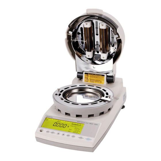
Page 16: Names Of Individual Parts And Components
4. Names of Individual Parts and Components 4-1 Names of Parts of Main Unit Heater lid Handle (Observation window) Heater Temperature sensor Wind shield Sample pan Sample pan handler Display Level Control panel Power switch Power conversion switch Power inlet RS-232C port Fuse holder Height adjustment legs... -
Page 17: Parts And Accessories
4-2 Parts and Accessories Sample pan (2) Sample pan handler (2) Wind shield Sample pan supporter Spoon and spatula (1 each) Spare 8A-fuses (2) Aluminum foil sheets (20) Power cord Three-prong plug adapter Instruction manual Protection Cover SALES & TECHNICAL SUPPORT QAQC LAB www.qclabequipment.com TEL (804) 318-3686... -
Page 18: Display And Control Panel
5. Display and Control Panel 5-1 Display 1 2 3 D Display as it appears with the power on. (All display items shown.) Item Name Description Stability indicator This indicator lights up when the balance is stable. Measuring completion indicator This indicator lights up when measuring has been completed. -
Page 19: Control Panel Operations
5-2 Control Panel Operations The control panel keys are used to perform the following operations. MENU CONDITION SELECT ENTER TARE/RESET START/STOP Name Operation Used to start measuring or to abort a measuring operation. Also used to turn off the alarm which sounds to indicate that a measuring operation has been START/STOP completed. -
Page 20: Assembly And Installation Of Main Unit
6. Assembly and Installation of Main Unit 1 Opening the package Open the package and check to make sure all listed items are included. 2 Installing the main unit Place the main unit on a flat, stable surface where it will not be subject to vibrations or exposed to drafts or breezes. - Page 21 5 Installing the wind shield Wind shield Open the lid of the heater, hold the wind shield by the Knobs Round knobs on the top, and place it on top of the pan holes supporter column so that the two round holes in the wind shield fit over the stays .
- Page 22 9 Close the heater lid Set the Protection Cover on the display. Adhesive tapes are attached to the Protection Cover. 0 Connecting the power cord Insert the female end of the power cord into the power inlet located at the rear of the unit. Then, attach the three-prong plug adapter to the power cord plug and insert the plug into power socket.
- Page 23 C Specifying the power voltage setting The specifiable voltages differ depending on the power setting with the power conversion switch described in B. Note: This setting must be done according to the power voltage available at the installation site. How to specify the power voltage setting Step Key(s) used Display...
-
Page 24: How To Conduct Measurements
7. How to Conduct Measurements Before beginning measurement, check to make sure that there is nothing remaining in the sample pan. Also be sure that all parts of the main unit are firmly fixed into place and be sure that the heater lid has been closed firmly before starting to perform measurements. - Page 25 Operating instructions Display 4 Performing a reset Close the lid of the heater, check to make sure that the stability indicator ( ) is being displayed, and then press the key. TARE/RESET When ‘-----’ and ‘TARE’ appear on the display, the sample pan moves upward and downward.
- Page 26 Operating instructions Display 7 Measuring time display While a measurement is being performed, the amount of time elapsed will be displayed in minutes. The change in moisture content over each 30-second interval is displayed numerically and in scalar format (where the scalar display may display a maximum change of 2 percent/30 seconds).
-
Page 27: Specifying Measuring Conditions
8. Specifying Measuring Conditions When using this tester to measure moisture or solid content, it is necessary to first specify the conditions (e.g., drying temperature or measuring mode) of the measurement. The settings to be specified are de- scribed below. It is also possible to save sets of measuring conditions (i.e., drying temperature, measuring mode, and bias). -
Page 28: Types Of Settings
8-2 Types of Settings Setting Display during Description specification of setting CONDITION CONDITION 0~9 Used to select the area to store condition settings. There are 10 storage areas labeled from 0 to 9. (See “8-3- (Measuring conditions 1 Selecting the CONDITIONS (Measuring conditions storage area)”.) storage areas 0~9) In automatic operation mode, measuring is brought to a end whenever the change in moisture content over (AUTO: Standard drying &... -
Page 29: Selecting The Conditions (Measuring Conditions Storage Area)
8-3-1 Selecting the CONDITIONS (Measuring conditions storage area) Below is described the procedure used to select the area in which measuring conditions are saved. This operation causes the measuring mode, drying temperature, bias, and other currently specified measuring conditions to be saved to the selected area. * At the time of shipment, the following settings are stored in measuring conditions storage areas 0~9: Measurement standard : Wet Base... -
Page 30: Selecting The Mode (Measuring Mode)
8-3-2 Selecting the MODE (Measuring mode) The ‘MODE’ (measuring mode) setting is used to specify the conditions under which measuring is to be completed. As shown in the table in subsection “8.1 Types of Settings”, the mode may be set to automatic operation mode, timed operation mode, or any one of five other modes. - Page 31 2) Specifying settings for TIME (Standard drying & Timed ending) mode In this mode, the measuring time is specified beforehand. When the specified measuring time is reached, measuring is ended. Measuring time may be specified in 1-minute increments anywhere in a range from 1 to 240 minutes or measuring may be specified to be performed over a continuous period of 12 hours.
- Page 32 3) Specifying settings for RAPID (High-speed drying) mode High-speed drying mode is useful for measuring samples with high levels of moisture content. In high-speed drying mode, the sample is dried at 180°C until the change M in moisture content over a 30- second period becomes lower than setting, then drying will be continued at the specified drying temperature.
- Page 33 Step Key(s) used Display Operating instructions Pressing the key will cause the units to switch between SELECT minutes (‘min’) and a percentage (‘%’). Press the key until the SELECT SELECT desired units are displayed. When the desired unit flashes, press the key.
- Page 34 4) Specifying settings for SLOW (Low-speed drying) mode In low-speed drying mode, the temperature is raised more gradually than when performing measurements under standard drying conditions, taking about 5 minutes until the temperature reaches the specified drying temperature. Either ‘AUTO’ (automatic ending mode) or ‘TIME’ (timed ending mode) may be specified to define the condition under which measuring is to be ended.
- Page 35 5) Specifying settings for STEP (Stepped drying) mode In stepped drying mode it is possible to specify separate drying conditions for up to a maximum of 5 steps. Specifying a separate drying temperature and measuring time for each step makes it possible to determine the optimum drying conditions for any sample type.
- Page 36 Step Key(s) used Display Operating instructions Pressing the key will cause the units to switch between SELECT minutes (‘min’) and a percentage (‘%’). Press the key until the SELECT SELECT desired unit is displayed. When the desired unit for the ending condition begins to flash, press the key.
- Page 37 Note: Read Section 12 before use of this part. 6) Specifying settings for COMPARE (Preparatory measuring) mode Preparatory measuring mode is used to calculate the bias (i.e., the difference between the measurement results which would be obtained in Standard drying & Automatic ending mode and predictive measuring mode) needed for predictive measurements.
- Page 38 Note: Read Section 12 before use of this part. 7) Specifying settings for PREDICT (Predictive measuring) mode Predictive measuring mode is used to predict the change in moisture content and calculate the predicted final measurement before drying has been completed. Thus measuring time can be saved. Note that some materials have properties which make it difficult to obtain accurate predictions.
-
Page 39: Temp (Drying Temperature) Setting
8-3-3 TEMP (Drying temperature) Setting The following describes the procedure to specify the drying temperature in conducting measurements. While the default drying temperature is 120°C, depending on the type of sample, its moisture content, or other conditions the proper drying temperature may vary. To find the proper drying temperatures for different types of materials, conduct repeated measurements until you find the correct temperature to use for each material. -
Page 40: Bias Setting
(standard) values as moisture measurements are the result of various conditions. The bias may be set to adjust the measured value by the MOC-120H to the expected (standard) value. Thus,the measured value using the MOC-120H can be treated to be equivalent to the existing (standard) measuring methed. -
Page 41: Menu Settings
9. Menu Settings MOC-120H provides the capability to specify and select between different measurement bases, data output formats, and other menu settings. All desired settings should be specified before conducting measurements. The procedure used when changing menu settings is the same as the procedure used when specifying menu settings for the first time. -
Page 42: Selecting A Measurement Base And Switching The % Display
9-2-1 Selecting the measurement base and switching the % display 1) Selecting the measurement base This menu item is used to specify what measurement base is to be used in measurements. There are three different types of bases: wet base, dry base, and solid. The type of base specified should be selected in accordance with the sample being measured. -
Page 43: Specifying The Type And Format Of Output
9-2-2 Specifying the type and format of output The MOC-120H may be connected to the optional printer or computer so that measurement data can be output. 1 There are three types of output formats as shown in the table below. - Page 44 How to specify the output format to be used Step Key(s) used Display Operating instructions With the display displaying the weight in grams, press the MENU key. MENU Press the key until the ‘OUTPUT’ menu item is displayed. SELECT SELECT Press the key.
- Page 45 Specifying the range of measurement values to be used (when ‘GRP’ has been selected) Step Key(s) used Display Operating instructions The currently selected lower limit of the range of data output will begin to flash. Press the key or key until the desired lower limit is displayed.
-
Page 46: Specifying Sample Codes
9-2-3 Specifying sample codes This section describes how to specify sample codes to be used when outputting measurements to the optional printer or a computer. Sample codes may be specified as 4-character codes. Any digit from 0 to 9, and letter from A to Z, or a hyphen “_” may be specified as the value of the first or second character of the code. -
Page 47: Setting The Date And Time
9-2-4 Setting the date and time This section describes how to set the date and time. Also note that the date and time of measure- ment are output whenever measurement data is output to the optional printer or a computer. How to set the date Step Key(s) used... -
Page 48: Cal (Balance Calibration)
9-2-5 CAL (Balance calibration) The internal balance of the MOC-120H may be calibrated at two points: at the 0 and 100grams. The MOC-120H may also be connected to a printer to make it possible to automatically generate calibration records in compliance with GLP, GMP, and ISO standards. -
Page 49: Specifying A Device Id
9-2-6 Specifying a device ID This section describes how to specify the device ID output when outputting data to the optional printer or a computer. The device ID is an 8-character ID which may be set using the following characters: digits from 0 to 9, letters from A to Z, and hyphens ‘—’. How to specify a device ID Step Key(s) used... -
Page 50: Specifying A Password
9-2-7 Specifying a password In order to prevent the specified measuring conditions from being modified unexpectedly, a pass- word may be specified to prevent other users from changing the specified conditions. The pass- word is 4 characters in length and may be set using the following characters: digits from 0 to 9, letters from A to Z, and hyphen. -
Page 51: Error Messages
Power error Turn the power off, make sure that the power conversion switch Er701 located on the back is set to the correct position. If any of the following errors are displayed, contact your Shimadzu representative. Message Description Er301 Temperature sensor failure... -
Page 52: Precaution On Conducting Measurements
11. Precaution on Conducting Measurements Precaution on conducting multiple measurements in succession Placing a sample on the sample pan which is already warm may cause moisture from the sample to evaporate before measuring is begun and causes errors in measurement result. Always be sure to use a cool sample pan when performing a subsequent measurement. -
Page 53: Predictive Measurements
However, because moisture balance operates by heating samples to evaporate the moisture content, it takes a fair amount of time to obtain results. MOC-120H has a feature that not only reduces measuring times but also brings the method to adjust partial drying measurement results to those obtained with a standard method of measuring. - Page 54 Preparatory measuring mode In preparatory measuring mode, predicted measurements are displayed while measuring is in progress and measuring is halted under the same conditions as when operating in automatic operation mode. The difference between the measured values of automatic operation mode and pedictive measuring mode is displayed as the necessary bias.
-
Page 55: Procedure For Obtaining Predicted Measurements
12-2 Procedure for Obtaining Predicted Measurements 1) Use preparatory measuring mode to obtain the appropriate bias value for the predictive mea- surement. (See “12-2-1 Calculating the bias to be specified when operating in predictive measure- ment mode” for instructions.) 2) Use the bias obtained in preparatory measuring mode in step 1) to perform the measurement, and evaluate the predicted measurement. - Page 56 Step Display Operating instructions Completion of measurement Measuring will be completed when the conditions specified for automatic operation mode have been met. When measuring is completed, the bias will be displayed in the bias display area. [Measurement results] Bias is + 0.60 ( = 16.40 (Automatic operation mode value) –...
-
Page 57: Evaluating Predictive Measurements
12-2-2 Evaluating predicted measurements Step Display Operating instructions With the mode set to preparatory measuring mode, set the bias obtained by the procedure described in 12.2.1. In the example shown here, a bias of 0.60 percent has been specified. (For information on how to set the bias, see “8-2-4 Bias”.) Do not change any other settings (i.e., the predicted value convergence range and drying temperature) at this time. -
Page 58: Performing Predictive Measurements
12-2-3 Preforming predictive measurements Step Display Operating instructions Set the mode to predictive measuring mode. Refer to 8.2.2 “7 Specifying settings for PREDICT (Predictive measuring) mode” for instructions. Specify the same settings for the predicted value convergence range and drying temperature as those used in preparatory measuring mode (subsections 12.2.1 and 12.2.2). -
Page 59: Temperature Calibration (Option Required)
13. Temperature Calibration (Option required) Temperature calibration can be performed with the optional temperature calibration kit. The calibration record meeting with GLP/GMP/ISO requirements can be automatically produced with the optional printer. Caution Do not touch heater cover and the sensor probe or holder of temperature calibration kit during temperature calibration as they become very hot. -
Page 60: Temperature Calibration Procedure
Temperature calibration procedure The following temperature calibration procedure can be entered only when 'ST' mode is selected as temperature display mode (Refer to 8.1). Verify that the °C symbol in the display is blinking, which indicates that currently selected mode is 'ST' mode. Install temperature calibration kit and switch on digital thermometer in advance. -
Page 61: Printing Output To A Printer (Option)
14. Printing Output to a Printer (Option) The MOC-120H may be connected to the optional printer to output measurement data. Output includes data consisting of intermediate or final measurements, sample codes, and measure- ment times. 14-1 Printer Output Sample Output of final results of more than one measurement... - Page 62 * Note on the decimal precision of printed weight data Although the minimum weight which may be displayed by the MOC-120H is 0.001 grams, weights are printed to a precision of 4 decimal points because the values printed consist of averages from 7 measurements taken over each 30-second interval for each set of weight data output.
- Page 63 Output of the intermediate and final values of a single measurement [Graph output (GRP)] Maker : SHIMADZU CORP Model : MOC-120H Serial number : D207300000 Device ID : ABCD-123 Sample code : B-20 Date & time of measurement : 2003/08/08, 15:07...
-
Page 64: Outputting Stored Measurement Data
Signature title 14-2 Outputting Stored Measurement Data The MOC-120H can store up to 100 sets of previous measurements data, and the stored data can be output to the optional printer or a computer. To output this data: 1 Follow the directions given on p. 31 in “9-2-2 Specifying the type and format of output” to set the output format to either ‘TBL’... -
Page 65: Computer Interface
15. Computer Interface The RS-232C interface may be used to connect the MOC-120H to a computer. 15-1 RS-232C Interface Specifications Interface type : RS-232C Communications method : Asynchronous communication Baud rate : 2400 bps Data bits : 8 bits Parity... -
Page 66: Setting Up And Transmitting Data
With the power to the MOC-120H and the computer both turned off, connect the RS-232C cable. Connect the RS-232C cable to the RS-232C port located at the rear of the MOC-120H and tighten the screws at both sides of the connector. Follow the same procedure to connect the RS-232C cable to the computer. - Page 67 8 Select a “Baud rate” of 300. 9 Click “OK”. 10 Click “Apply” and wait. 11 Click “OK”. SALES & TECHNICAL SUPPORT QAQC LAB www.qclabequipment.com TEL (804) 318-3686...
-
Page 68: Starting Up The Computer
15-2-4 Starting Up the Computer Turn on the power to the computer and when Windows has started up open the Microsoft Excel or whatever software is to be used to read in data. * For instructions on how to use your computer, operating system (Microsoft Windows), or software being used, see the user manuals provided with them. -
Page 69: Computer Output Format
15-3 Computer Output Format Interface type : RS232C Numeric output format : JIS (ASCII) Delimiter code : 0x09 (tab) Delimiter : 0x0D (CR) + 0x0A(LF) Title output format at time of start of measurement (Underscore characters (i.e., ‘–’) are used below to indicate blanks (i.e., ‘20’ in hexadecimal) _SHIMADZU-CORP”... - Page 70 Stepped mode format “_Mode_:_Step” tab + “Temp” + tab + “Time” + delimiter The following output then appears the same number of times as the number of specified steps: “_Step” + “X” (1-byte step number) + tab + “XXX” (3-byte temperature setting) + tab + “XXX”...
-
Page 71: Maintenance
16. Maintenance 16-1 Performing Maintenance Turn the power off and disconnect the power cable. Allow the heater and other parts cool down to ambient temperature before performing maintenance. Removing and reinstalling parts and components Remove the sample pan, then the sample pan handler, sample pan supporter, and wind shield in this order. -
Page 72: Replacing Fuses
(8A). 5 Return the fuse holder to its original position in the main unit. 6 Insert the power cord back into the main unit. Should the fuse(s) blow out repeatedly after replacement, contact your Shimadzu representative. SALES & TECHNICAL SUPPORT... -
Page 73: Parts List
17. Parts List Standard Accessories Item Part number Description Sample Pan 321-63314 Sample Pan Handler 321-63315 Wind Shield 321-63316 Sample Pan Supporter 321-63317 Spoon Spatula Set 321-63318 Fuse, 8A, 2 pcs Set 321-63319 Aluminum Foil Sheet 10 pcs Set See below for order Protection Cover See below for order Optional Accessories and Consumables List... - Page 74 Specifications of Printer cable and RS-232C communication cable Printer cable P/N:321-63307 MOC-120H Printer Side Side D-sub9P D-sub9P Plug Plug SIGNAL G N D RS-232C Cable P/N:321-63308 MOC-120H PC Side Side D-sub9P D-sub9P Socket Plug SIGNAL G N D SALES & TECHNICAL SUPPORT...
- Page 75 SALES & TECHNICAL SUPPORT QAQC LAB www.qclabequipment.com TEL (804) 318-3686...
- Page 76 SALES & TECHNICAL SUPPORT QAQC LAB www.qclabequipment.com TEL (804) 318-3686...
Need help?
Do you have a question about the MOC-120H and is the answer not in the manual?
Questions and answers