
Related Manuals for Shimadzu MOC-120H


Summary of Contents for Shimadzu MOC-120H
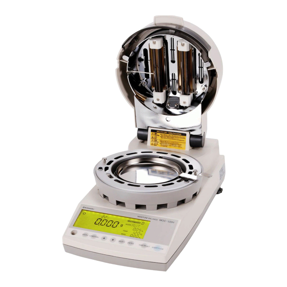
- Page 1 321-78153 Aug, 2014 ELECTRONIC MOISTURE METER MOC-120H SERVICE MANUAL SHIMADZU CORPORATION Kyoto,JAPAN...
-
Page 2: Table Of Contents
Contents 1. Table of Malfunction Causes 2. Troubleshooting 3. Service Mode of MOC-120H 4. Replacing the Heater Assembly 5. Replacing the Thermal Fuse Assembly 6. Replacing the Thermistor 7. Replacing the Motherboard 8. Replacing the Motor and PI Board Assembly 9. -
Page 3: Table Of Malfunction Causes
1.Table of Malfunction Causes Malfunction Causes Solutions Inspection Method After Repairs Power will not 1 Power cord not Connect power Turn power on again turn on connected cord (LCD does 2 Fuse disconnected Replace fuse not light) 3 Power voltage Use with correct malfunction power... - Page 4 Malfunction Causes Solutions Inspection Method After Repairs Er. 102, 103, 1 Incorrect usage Use properly Check proper usage 2 Malfunction due to ROM Replace Complete acceptance Er. 201, 202 ver. 7212 or earlier motherboard inspection 3 Improper lift unit adjustment Readjust lift unit Heat drift test Er.
- Page 5 Malfunction Causes Solutions Inspection Method After Repairs Er. 401 1 Bad balance connector Reattach Complete acceptance contact connector inspection 2 Balance board malfunction Replace balance Complete acceptance board inspection 3 Motherboard malfunction Replace Complete acceptance motherboard inspection 4 Balance malfunction Replace balance Complete acceptance inspection Er.
- Page 6 Malfunction Causes Solutions Inspection Method After Repairs Er. 701, 702 1 Incorrect usage (power Use properly Check proper usage selection SW) 2 Power voltage problem Use correct Turn power on again power 3 SW power malfunction Replace SW Turn power on again power Er.
-
Page 7: Troubleshooting
2.Trouble shooting 2-1【 Er. 102, 103, 104, 201, 202 】 2-2【 Er. 301, 302 】 - 5 -... - Page 8 2-3【 Er. 303 】 2-4【 Er. 304 】 - 6 -...
- Page 9 2-5【 Er. 305 】 2-6【 Er. 306 】 - 7 -...
- Page 10 2-7【 Er. 401 】 2-8【 Er. 501,502 】 - 8 -...
- Page 11 2-9【 Er. 603 】 2-10【 Er. 701,702 】 - 9 -...
- Page 12 2-11【 Er. 801 or 802 】 2-12【 Heater does not light up 】 - 10 -...
- Page 13 2-13【 Mass Measurement is Unstable 】 2-14【 After Turning Power On, “CHEO”, “-oL” or Other Display Does Not Turn Off 】 - 11 -...
- Page 14 2-15【 Power will not turn on (LCD does not light) 】 - 12 -...
-
Page 15: Service Mode Of Moc-120H
3.Service Mode of MOC-120H Key 1 Key 2 Action START+TARE+ENTER EEPROM data set to factory setting CONDITION+MENU Power SW Balance TAD, WAD output in measuring START or TARE All segment indicate ENTER EEPROM data output START Range of zero trucking set... -
Page 16: Replacing The Heater Assembly
Open while pushing it over Open upper case to the left and stand it up while taking care with the as is without completely harness lead. disassembling. Zero cross board Heater Of the connectors on the upper Heater part of the zero cross board, the two on the back portion of the device are for the heater. -
Page 17: Replacing The Thermal Fuse Assembly
Open the upper case while taking care with the harness lead. Open while pushing it over to the left and stand it up as is without completely disassembling Remove the lead line from the Zero cross board cord clip at the side of the connector and the cord clip on the upper case. -
Page 18: Replacing The Thermistor
Open upper case Open while pushing it over while taking care with the to the left and stand it up harness lead. as is without completely disassembling Pan support arm To prevent the pan supporter arm (the female thread side) from turning when attaching the pan supporter shaft (top), tighten the screws while holding the pan supporter shaft as shown in the picture. -
Page 19: Replacing The Motherboard
●Checking the board To prevent the pan supporter arm (the female thread side) from turning when attaching the pan Peel off the LCD protection sticker Set the battery supporter shaft (top), tighten the screws while holding the pan supporter shaft as shown in the picture. -
Page 20: Replacing The Motor And Pi Board Assembly
To prevent the pan supporter arm (the female thread side) from turning when attaching the pan supporter shaft (top), tighten the screws while holding the pan supporter shaft as shown in the picture. Pan support arm If the pan supporter arm turns and touches other parts,... -
Page 21: Replacing The Balance Assembly
When moving the balance, hold the base (the part marked with an arrow) and do not make strong contact with the other parts. Especially do not touch the thin line indicated by the circle. Open upper case while taking care with the harness lead. - Page 22 - 20 - - 20 -...
-
Page 23: Readjusting The Heater Cover
- 21 - - 21 -... -
Page 24: Adjusting The Linearity Of The Electric Balance Unit
11. Adjusting the Linearity of the Electric Balance Unit 1) Remove the five screws holding the upper case assembly and remove the upper case assembly from the bottom case assembly. Lower the left side of the upper case assembly and stand it up on the left side of the main unit. 2) Detach the black cable in front of the balance board on the right side of the electronic balance unit. -
Page 25: Parts List
12. Parts list - 23 -... - Page 26 321-64147-01 PI board ASSY(1Hole) Non-RoHS 321-64147-11 PI board ASSY(1Hole) RoHS 321-64144 Thermistor ASSY 321-64145 Lift unit ASSY 321-63312 Panel sheet MOC-120H Parts 321-64148 Power board ASSY Non-CE *2 321-64148-01 Power board ASSY(CE) 321-64165 Power change-over switch ASSY 321-64169 Display filter...
- Page 27 321-75683 Base rearing(R) 031-40204-01 Dry metal 321-75691 Blank cap 037-30059-03 Damper rubber 321-75692 Base axis 321-75697 Dirt avoids 321-75698 Supporter arm ASSY The top of three 321-63285-90 KETT ASSY,UNI_ILS ILS CN, Non-RoHS 321-63285-91 KETT ASSY,UNI_ILS ILS CN, RoHS 321-63285-92 KETT ASSY,UNI_PH PH CN, RoHS 321-63220 Pre-amp board ASSY,KETT...
- Page 28 Jig for old lift system Jig for new lift system - 26 -...
- Page 29 Parts Name Note Lift adjuster Center adjuster 321-64154 Lift adjustment jig set Center height adjuster Level adjuster 321-69280 Hex wrench, M2 321-69278 Lift adjuster 321-69279 Flange height adjustment tool 321-64156 Tension spring adjustment jig 321-69275 Adjustment case ASSY,KETT_IL ILS CN, non-RoHS 321-69275-43 Adjustment case ASSY,KETT_IL ILS CN, RoHS...
Need help?
Do you have a question about the MOC-120H and is the answer not in the manual?
Questions and answers