Table of Contents
Advertisement
Quick Links
Advertisement
Table of Contents

Related Manuals for Shimadzu UV-1700 series


Summary of Contents for Shimadzu UV-1700 series
-
Page 1: Service Manual
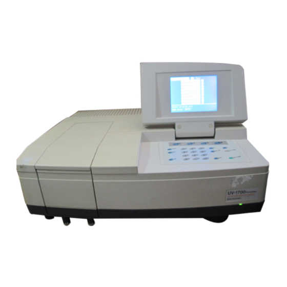
206-98366A UV-Vis Spectrophotometer UV-1700 series SERVICE MANUAL 206-55401-34 for 230V CE 206-55401-91 for 100V 206-55401-92 for 120V 206-55401-93 for 220V 206-55401-94 for 240V SHIMADZU CORPORATION ANALYTICAL INSTRUMENTS DIVISON KYOTO JAPAN... -
Page 2: Table Of Contents
Contents 1. Introduction 1.1 About the Service Manual 1.2 UV-1700 Outline 1.3 Intended Use 1.4 Warning Labels on Instrument 2. Installation 2.1 Inspection of Parts 2.2 Selection of Installation Site 2.3 Installation of UV-1700 2.4 Instrument Baseline Correction 3. Performance Checks 3.1 Notes on the Performance Checks 3.2 How to Use Instrument Validation 3.3 ROM Check... - Page 3 6. Troubleshooting 6.1 An Error Occurs During Initialization 6.2 Baseline Flatness Exceeds Specification 6.3 Noise Level Exceeds Specification 6.4 Wavelength Accuracy Exceeds Specification 6.5 Wavelength Repeatability Exceeds Specification 7. Parts Replacement 7.1 Main Unit Cover Removal 7.2 Console PCB Removal 7.3 Preamplifier PCB Removal 7.4 Power PCB Removal 7.5 CPU PCB Removal...
- Page 4 10.13 PCB ASSY, Console 10-16 11. Electric Circuit Diagram 11-1 11.1 Electrical Block Diagram 11-2 11.2 CPU P.C.Board 11-3 11.3 Preamp P.C.Board 11-9 11.4 Power P.C.Board 11-10 11.5 Console P.C.Board 11-11...
-
Page 5: Introduction
Chapter 1 Introduction This chapter explains instrument outline, intended use of service manual and warning labels. 1.1 About the Service Manual 1.2 UV-1700 Outline 1.3 Intended Use 1.4 Warning Labels on Instrument... -
Page 6: About The Service Manual
Receiving service training is a prerequisite for the correct use of this manual. Note that Shimadzu will not bear responsibility for problems that may occur when a person who has not received specific service training operates the instrument according to this... -
Page 7: Warning Labels On Instrument
1.4 Warning Labels on Instrument Warning labels are attached to the UV-1700 in the following two locations. Be sure to thoroughly read the instruction manual in advance and adhere to instructions provided when replacing lamps or fuses to avoid injuries such as burns and electric shocks. WARNING DANGER, High Temperature The light source and light source compartment become extremely hot during operation. -
Page 8: Installation
Chapter 2 Installation This chapter explains how the UV-1700 is installed. Be sure to adhere to the procedures in this chapter when performing installation work so that the instrument performs appropriately to ensure customer satisfaction. 2.1 Inspection of Parts 2.2 Selection of Installation Site 2.3 Installation of UV-1700 2.4 Instrument Baseline Correction... -
Page 9: Inspection Of Parts
2.1 Inspection of Parts UV-1700 standard contents are shown in Table 2.1 and figure 2.1. Check these together with the customer to see that all parts have been delivered. Table2-1 Standard Contents Description Qty. Spectrophotometer UV-1700 Main unit For 230V CE area 206-55403-34 For 100V area 206-55403-91... - Page 10 Fig.2-1 Standard contents (items 5 is not displayed)
-
Page 11: Selection Of Installation Site
2.2 Selection of Installation Site Meet with the customer and decide upon a suitable installation site before commencing installation of the UV-1700. And be sure to install the instrument in a site that conforms to the following parameters to ensure that the instrument will perform appropriately and stably over a long period. -
Page 12: Installation Of Uv-1700
2.3 Installation of UV-1700 Once the installation site has been decided, install the UV-1700 in accordance with the following procedures. 2.3.1 Power Check The UV-1700 uses a 130VA power supply. Be sure to use a power supply of at least 130VA (if a PC system is to be used, PC and printer power supplies must be taken into consideration as well). -
Page 13: Instrument Baseline Correction
2.4 Instrument Baseline Correction Once installation is complete, be sure to carry out instrument baseline correction following the steps below. 1) Turn ON the power switch of the UV-1700. Maintenance After checking that initialization has ended 1.Validation correctly, energize the instrument for at 2.Instrument Baseline Correction Corrected date: 01/03/30 11:36:00 least 30 minutes to stabilize it. -
Page 14: Performance Checks
Chapter 3 Performance Checks This chapter explains how to check basic performance of the UV-1700. Note that items accompanied by an asterisk (*) require checking as part of the acceptance procedures. 3.1 Notes on the Performance Checks 3.2 How to Use Instrument Validation 3.3 ROM Check* 3.4 Wavelength Accuracy* 3.5 Wavelength Repeatability... - Page 15 3.1 Note on the Performance Checks 3.1.1 About ROM Check Activating the instrument while holding down the [F1] key sets the instrument validation measuring parameters and pass criteria values to the default settings, which are different to the normal parameters. 3.1.2 Checking of Baseline Stability To implement baseline stability inspection, the instrument power supply must be turned ON for at least one hour prior to inspection.
-
Page 16: How To Use Instrument Validation
3.2 How to Use Instrument Validation Use the instrument validation functions installed in the UV-1700 to check basic performance. This item explains how these functions are used. 3.2.1 How to Enter Instrument Validation Mode 1) Press [F3] key Mainte. at the mode selection Validation screen to display the Maintenance screen. - Page 17 3.2.3 Printout Press the [F1] key PrintOut to printout the inspection results just obtained. Inspection results are stored in backup memory, so they will be saved even if the power is turned OFF. Note, however, that the printout function does not printout graph data such as spectrum and time course.
- Page 18 2) Select one of the items (1 to 7) to enter the parameter settings screen for that inspection item. Setting changes to “Inspection: Yes/No”, inspection parameters and pass criteria values can be made here (see inspection items for details). Note A password can be eliminated, when the administrator of UV-1700 forgets the password and does not put into the condition setting screen of Semi-Auto items / Auto items.
-
Page 19: Rom Check
3.3 ROM Check Specification: Latest checksum value [Checking Method] Initialization : Pass 1) Hold down the [F1] key and turn ON the LSI Initialize power. Release the key once the buzzer ROM Check 30957 beeps. RAM Check 2) Initialization starts and the initialization Filter Origin Light Source Org.: menu will be displayed on the LCD. -
Page 20: Wavelength Accuracy
3.4 Wavelength Accuracy In the case of the UV-1700, wavelength accuracy can be checked with the following two methods. a) Method employing a D lamp line (656.1nm, 486.0nm) b) Method employing wavelength correction filter Use method a) to check wavelength accuracy at time of installation. Note that at time of shipping, wavelength is corrected using the Holmium oxide solution filter (NIST SRM2034, P/N 220-92917-01).This item explains the wavelength accuracy checking method using the Holmium oxide solution filter. - Page 21 Recommended Value The pass criteria value can be set to a recommended value. Do not use this item at this point. 3) Press the [RETURN] key twice to return to the instrument validation screen. Now press the [START] key to implement inspection followed by printout of results. 4) Check that wavelength accuracy is within ±...
- Page 22 Inspection Wavelength accuracy Each press of the [1] key selects (Yes) or 1.Inspection: 2.Method: Filter deselects (No) inspection. 3.Check λ(nm): inspection to the "Yes” item. 640.5 536.6 485.3 467.8 416.3 Method 385.7 361.3 345.5 333.4 287.2 278.1 249.9 241.1 Press the [2] key to open an interactive 4.Tolerance: ±...
-
Page 23: Wavelength Repeatability
3.5 Wavelength Repeatability This checks wavelength repeatability by measuring the D lamp line (656.1nm, 486.0nm) three times, and verifying the deviation between the average value and each individual measuring value. Specification: Within ± 0.1nm [Checking Method] Wavelength repeatability 1) Press the [2] key at the auto items screen to 1.Inspection: display wavelength... -
Page 24: Resolution
3.6 Resolution This measures the 656.1nm line of the D lamp, takes the peak half height width of the spectrum waveform, defines it as a resolution and checks that value. Specification: 1.0nm or less [Checking Method] 1) Press the [3] key at the auto items screen to Resolution display the resolution parameter settings 1.Inspection:... -
Page 25: Baseline Stability
3.7 Baseline Stability This measures the time variation in the vicinity of zero absorption (0Abs) for the specified wavelength, and checks the hourly rate of variation. Specification: Within 1.0mAbs/h ( @700nm ) [Checking Method] 1) Press the [4] key at the auto items screen to Baseline Stability 1.Inspection: display the baseline stability parameter... -
Page 26: Baseline Flatness
3.8 Baseline Flatness This corrects the baseline to a blank status at both the sample (S) and reference (R) sides of the sample compartment, measures the spectrum, and uses the amount of curve to check baseline flatness. Specification: Within ± 2mAbs (note that shock noise should be within 4mAbs) [Checking Method] 1) Press the [5] key at the auto items screen to Baseline flatness... - Page 27 Note To implement baseline flatness inspection, the instrument power supply must be turned ON for at least one hour prior to inspection. A warning message will be displayed if one hour has not elapsed from when the power was turned ON. 3-14...
-
Page 28: Noise Level
3.9 Noise Level This measures for one minute the time variation in the vicinity of zero absorption (0Abs) for the specified wavelength, and checks the P-P noise from that amplitude. It also calculates the RMS value from the one-minute data. Specification: P-P Within 2mAbs (same for each wavelength) 0.2mAbs or less (@700nm) 0.3mAbs or less (@500nm) - Page 29 5) Set the inspection wavelength to 250nm and the RMS value of the pass criteria value to within 0.4mAbs. And inspect the noise level. 6) Check that each inspection result conforms to the specification. 3-16...
-
Page 30: Photometric Accuracy
3.10 Photometric Accuracy This measures the optic filter for transmittance correction, checks the deviation against the validation value and makes the result the photometric accuracy. Check photometric accuracy using the semi-automatic inspection item in the instrument validation functions. Specification: Within ± 0.002Abs (vicinity of 0.5Abs) Within ±... - Page 31 Inspection Each press of the [1] key selects (Yes) or deselects (No) the inspection. Set inspection to the "Yes” item. Meas. Mode Each time the [2] key is pressed the " Abs/%T" will change together with validation value for the inspection filter and the pass criteria value. Use the “Abs” mode. Check λ...
- Page 32 4) Return to the instrument validation screen. 5) With the filter set, load the CPS-240A (kept at a constant temperature) into the sample compartment. 6) Check that the CPS-240A cell position is “Cell 1”, and press the [START] key to start inspection.
-
Page 33: Photometric Repeatability
3.11 Photometric Repeatability This repeatedly measures three times the photometric value that occurs in the specified wavelength of the optic filter for transmittance correction, and determines the deviation between the average value and each individual measuring value to check photometric repeatability. - Page 34 3) Press the [RETURN] key twice to return to the instrument validation screen. Now press the [START] key to implement inspection. Take out and put in inspection filters in accordance with screen instructions. Results will be printed out when the inspection is completed.
-
Page 35: Stray Light
3.12 Stray Light Stray light is defined as (light intensity of a wavelength other than the set wavelength)/(light intensity of set wavelength). Here, the transmittances at 220nm of sodium iodide aqueous solution (10g/l) and at 340nm of sodium nitrite aqueous solution (50g/l) or a UV-39 filter are determined, and the amount of stray light in each wavelength checked. - Page 36 3) Press the [RETURN] key twice to return to the instrument validation screen. Now press the [START] key to implement inspection. Take out and put in inspection samples in accordance with screen instructions. Results will be printed out when the inspection is completed.
- Page 37 Chapter 4 Acceptance Procedures This chapter details the acceptance procedures for the UV-1700. 4.1 Acceptance Procedures...
- Page 38 4.1 Acceptance Procedures Check these together with the customer to see that the specifications are fulfilled for the following items after installing the UV-1700. Inspection Method and Results Item Specification Check 1.Installation Main unit installation site conditions See “2.2 Selection of must be fulfilled.
- Page 39 6.Baseline flatness Use the validation check functions Baseline flatness: Within ± 0.002Abs to determine baseline flatness. Shock noise: Within 0.004Abs 7.Noise level Use the validation check functions P-P: Within 0.002Abs to determine noise level. 700nm 500nm 250nm 8.Handling explanation Explain how the instrument is used Explain basic in accordance with the instruction...
-
Page 40: Periodical Check
Chapter 5 Periodical Check This chapter explains the periodical checks for the UV-1700. Recommend these periodical checks to customers for safe, prolonged use of the instrument. 5.1 Daily Checks 5.2 Monthly Checks... -
Page 41: Daily Checks
5.1 Daily Checks 5.1.1 Cooling Fan Operation Check Check that the cooling fan on the left side of the main unit is operating. If the cooling fan is not working, the light source compartment will overheat, the safety unit (temperature switch) will activate and the WI lamp will not light up. - Page 42 5.2.2 Light Source Check The average lifespan of the WI lamp is 2000 hours and the D lamp is 500 hours. As a lamp nears the end of its lifespan, brightness decreases and signal noise increases. The remaining lamp lifespan can be checked at the maintenance screen. If a lamp has exceeded its average lifespan, replace it.
-
Page 43: Troubleshooting
Chapter 6 Troubleshooting This chapter explains the troubleshooting method for the UV-1700. 6.1 An Error Occurs During Initialization 6.2 Baseline Flatness Exceeds Specification 6.3 Noise Level Exceeds Specification 6.4 Wavelength Accuracy Exceeds Specification 6.5 Wavelength Repeatability Exceeds Specification... -
Page 44: An Error Occurs During Initialization
6.1 An Error Occurs During Initialization Error Items Probable Cause Action ROM Check - ROM chip defective Replace ROM - ROM content destroyed - ROM pin broken Repair pin - ROM socket defective Replace CPU PCB - ROM socket solder defective RAM Check - Insufficient backup battery voltage Replace battery... - Page 45 Error Items Probable Cause Action W Lamp Energy When WI lamp does not light up - WI lamp defective Replace lamp - WI lamp lighting circuit defective Replace power (PCB ASSY, POWER) or CPU PCB - Cable broken Replace cable When WI lamp lights up - Lamp energy loss Replace lamp...
- Page 46 Error Items Probable Cause Action λ Check The 656.1nm line cannot be detected (energy value is 425 or less) - Lamp energy loss Replace lamp - Light source position defective Adjust light source mirror and lamp positions - Preamplifier defective Replace preamplifier PCB - Stray light cut filter defective Replace filter ASSY, check for...
-
Page 47: Baseline Flatness Exceeds Specification
6.2 Baseline Flatness Exceeds Specification Probable Cause Action - Instrument baseline correction has not been Correct instrument baseline performed. - Baseline correction has not been performed. Correct baseline - Status has changed since instrument baseline Correct instrument baseline was corrected. Or instrument baseline has not been corrected for a long time. -
Page 48: Wavelength Accuracy Exceeds Specification
6.4 Wavelength Accuracy Exceeds Specification Probable Cause Action - Sample, etc., is set in cell holder. Empty sample compartment - Wavelength drive motor defective Replace or readjust motor - CPU PCB defective Replace CPU PCB 6.5 Wavelength Repeatability Exceeds Specification Probable Cause Action - Wavelength drive motor defective... -
Page 49: Parts Replacement
Chapter 7 Parts Replacement This chapter explains the parts replacement of UV-1700. 7.1 Main Unit Cover Removal 7.2 Console PCB Removal 7.3 Preamplifier PCB Removal 7.4 Power PCB Removal 7.5 CPU PCB Removal 7.6 ROM Replacement 7.7 Battery Replacement... -
Page 50: Main Unit Cover Removal
7.1 Main Unit Cover Removal Fig.7-1 Main unit 1) Loosen screws (1), and remove sample compartment unit. Fig. 7-2 Main unit (top) 2) Remove cover screws (3 to 6). 3) Slightly raise the rear of the cover, slide the entire cover forward and lift up to remove. Note A console PCB is mounted to the cover. -
Page 51: Console Pcb Removal
7.2 Console PCB Removal Fig.7-3 Inside of cover unit Remove the main unit cover and place on the workbench with the inside of the cover showing. Remove the four screws (1-4) holding the console PCB. Disconnect the three wiring connectors connected to the console PCB. And remove the board. -
Page 52: Power Pcb Removal
7.4 Power PCB Removal Fig.7-5 Power PCB Removal Remove main unit cover. Remove screws in locations 1 to 4. Loosen screws 5 and 6, and remove power PCB. 7.5 CPU PCB Removal Fig.7-6 CPU PCB Removal Remove screws in locations 1 to 4. Pull out unit with CPU PCB from the right side of the main unit. -
Page 53: Rom Replacement
7.6 ROM Replacement Pull out CPU PCB from right side of main unit (see item 1 of 7.5). Remove and replace ROM OB 1700 (P/N 206-55221-92), ROM MODE 1700 (P/N 206-55222-92). Note With the UV-1700, ROM MODE 1700 contains adjusting information such as wavelength tables (this is contained on a separate EEPROM in the case of the UV-1600). - Page 54 A message will ask you if you really want to rewrite. Press the [START] key to select the “Yes” item. Press any other key to select the “No” item. Here, press the [START] key to initialize the RAM.1) 8) Turn OFF instrument power. 3.Condition set 1.EEPROM data initialize 2.Instrument ID No.=...
-
Page 55: Adjustment Procedures
Chapter 8 Adjustment Procedures This chapter explains adjustment methods mainly for the optical system of the UV-1700. 8.1 Jigs and Tools Required 8.2 Before Starting Adjustment 8.3 Adjustments... -
Page 56: Jigs And Tools Required
8.1 Jigs and Tools Required 8.1.1 Jigs 1) Target ruling (H = 39.8mm) P/N 775-05135 2) Adjusting jig mirror (for S side) P/N 775-06865-02 3) Optical axis adjustment plate P/N 775-06116 4) Adjusting jig (H = 40mm) P/N 775-04313-11 *Optical axis adjustment plate included 5) Mercury lamp holder P/N 206-55895-92 * ASSY with lamp (see No. -
Page 57: Before Starting Adjustment
8.2 Before Starting Adjustment 8.2.1 Launching Maintenance Mode Launch the maintenance mode using the following operation. 1) Hold down the [START] key and turn ON the Maintenance main unit power. Release the [START] key 1.Drive check when the buzzer beeps. 2.Optics check 2) The sound of stray light cut filter origin 3.Condition set... - Page 58 (1) Wavelength Drive PM Select this item to rotate the grating. This is 1.Drive check used to adjust the grating unit and move the 1.Wavelength drive PM line on the exit slit. It cannot be used to set 2.Light source mirror PM special wavelengths.
- Page 59 (2) Light Source Mirror PM Use this to operate the light source switching mirror of the light source unit. Press the [2] key to select light source mirror 1.Drive check PM. Function keys will be displayed at the 1.Wavelength drive PM bottom of the screen.
- Page 60 (3) Filter PM Use this to operate the stray light cut filter and memorize filter positions. Press the [3] key to select the "Filter PM." 1.Drive check Function keys will be displayed at the 1.Wavelength drive PM bottom of the screen. 2.Light source mirror PM 3.Filter PM 4.Cell drive(Multicell[6])PM...
- Page 61 (4) Cell Drive (Multicell [6] PM) Use this to operate the special accessory multicell holder. Press the [4] key to select the cell drive 1.Drive check (multicell [6]) PM. Function keys will be 1.Wavelength drive PM displayed at the bottom of the screen. 2.Light source mirror PM 3.Filter PM 4.Cell drive(Multicell[6])PM...
- Page 62 (5) Sipper PM Use this to operate the special accessory sipper. Press the [5] key to select sipper PM. 1.Drive check Function keys will be displayed at the 1.Wavelength drive PM bottom of the screen. 2.Light source mirror PM 3.Filter PM 4.Cell drive(Multicell[6])PM 5.Sipper PM 6.CPS-240...
- Page 63 (6) CPS-240 Use this to move the cell holder of the special accessory CPS-240 and check the cell position utilizing zero-order light. Press the [6] key to select CPS-240. Function keys will be displayed at the 1.Drive check bottom of the screen. 1.Wavelength drive PM 2.Light source mirror PM 3.Filter PM...
- Page 64 8.2.3 Outline of Optical System Check Select “2. Optics check” at the top menu 2.Optics check screen to display the screen shown in Fig. 8-9. 1.0 ord. light search point set Use this to check zero-order light search 2.0 ord. light search point and D /Hg line wavelengths as well as 3.Hg lamp line λ...
- Page 65 (2) Zero-Order Light Search Use this to check that the zero-order light is correctly detected for both the WI and D lamps. After setting the first item “1. 0 ord. light search point set”, check that the settings have been saved correctly. After setting, this item can be used to check the optical axis and the cell position when the sipper is mounted.
- Page 66 (3) Hg lamp line λ detection The Hg and D lamps are used to correct wavelength in addition to the Holmium oxide solution in UV-1700. Use this to check wavelength correction. 1) Press the [3] key at the optic check screen 3.Hg lamp line λ...
- Page 67 (4) Resolution Check Use this to check the peak half height width of the D lamp line. 1) Press the [4] key at the optic check 2.Optics check screen to select “4. Resolution check”. 1.0 ord. light search point set 2) The spectrometer automatically...
- Page 68 8.2.4 Outline of Condition Setting Select “3. Condition set” at the top menu 3.Condition set screen to display the menu shown in Fig. 8-14. 1.EEPROM data initialize Use this to initialize data saved in FlashROM 2.Instrument ID.No.= *********** and input instrument ID number and 3.ABS corr.
- Page 69 * The following items are contained in the adjustment data domain. - Wavelength table: Table with values corrected using Hg/D lamp lines - Zero-order light detection origin: Origin offset value for zero-order light detection - Stray light cut filter position: Phase setting value for filter motor - Instrument ID No.
- Page 70 a) Measure the absorbance that occurs in the standard wavelength of a substandard filter in photometric mode. b) Determine the factor using the calculating formula: Standard value (Abs) / Measuring value (Abs) = [Correction Factor] (4) Initializing After Battery Change Use this to initialize data written in RAM when changing the battery.
-
Page 71: Adjustments
8.3 Adjustments 1. Adjustment of light source optical axis Use the D lamp beam to adjust light source switch mirror and WI lamp height. - Adjustment of light source switch mirror position (perpendicularly to entrance slit) - Adjustment of WI lamp holder position (perpendicularly to entrance slit) 2. - Page 72 8. Performance check Turn OFF and then ON again main unit power, and check the following. - Initialization correctly finishes. - Performance check of Condition set mode correctly finishes. - After instrument baseline correction, Abs zero flatness and noise level are within specifications.
- Page 73 8.3.2 Adjustment of Light Source Optical Axis Adjustment of the light source optical axis is performed by adjusting the height of the light source switch mirror and WI lamp based on the height of the D lamp beam. (1) Adjustment of Light Source Switch Mirror 1) Select “1.
- Page 74 (2) Adjustment of WI Lamp Holder Height 1) Press the [F4] key at the “2. Light source mirror PM” screen to extinguish the D lamp. 2) Press the [F3] key to light up the WI lamp. Put the light source mirror motor into drive and align the WI lamp beam over the entrance slit.
- Page 75 8.3.3 Adjustment of Grating The spectral band created by the grating is used to adjust ruling and inclination of grating. 1) Follow steps 1 to 3 of item 8.3.2 (2) to align 1.Drive check the WI lamp beam over the entrance slit. 1.Wavelength drive PM 2) Select “1.
- Page 76 4) Retighten the fixing screw B. Next, tighten the tilt adjustment bolts until they lightly touch the flange of the plate. Grating Tilt adjustment bolts Plate B fixing screw Fig.8-23 Grating holder side view 5) Loosen the fixing screw A holding the grating. 6) Rotate the grating until the beam band is parallel with the marking line on the adjusting jig.
- Page 77 * When diffracted light center is below adjusting jig centerline (horizontal line) Use the bottom side tilt adjustment bolt to align diffracted light center with adjusting jig centerline, and tighten tilt adjustment bolt. Now retighten the fixing screw B and recheck alignment.
- Page 78 8.3.4 Adjustment of Double Beam Optics The light beam divided into two by the half mirror is made to pass through the sample compartment by adjusting the mirrors at the sample and reference sides. P.D. Ref. P.D. Sam. Fig.8-26 UV-1700 optical system diagram 1) Follow items 1 to 3 of procedure 8.3.2 (2) to align the WI lamp beam with the entrance slit.
- Page 79 Fixing screws B Fixing screws A (for position adjustment) R side mirror (M5) Toroidal mirror (M2) Fixing screws A Tilt adjustment bolts Fixing screws A Fixing screws B (for position adjustment) Tilt adjustment bolts S side mirror (M4) Fig.8-27 Toroidal mirror surroundings 7) Retighten the fixing screws A on the toroidal mirror (M2) to fix tilt adjustment unit after adjusting height.
- Page 80 14) Place the adjusting jig (H = 40mm) in front (right side) of the sample compartment quartz windowpane over the marking line of the optical axis adjustment plate. And adjust the toroidal mirror (M2) in the left and right directions so that the beam comes to the center in the horizontal direction of the adjusting jig.
- Page 81 20) Change the position of the adjusting jig (H = 40mm) and check that the beam is in the center of the adjusting jig whatever the position of the adjusting jig over the marking line. * Place pieces of card (like a business card) over the R side mirror (M5) and check that the beam is not escaping over the edges of the mirrors.
- Page 82 Exit slit “No filter” position Fig.8-30 Stray light cut filter (2) Zero-Order Light Search Point Set 1) Select “2. Optics check” from maintenance 2.Optics check mode top menu followed by “1. 0 ord. light 1.0 ord. light search point set search point set”.
- Page 83 Approx. 5mm Approx. 5mm EExit slit Beam (zero-order light) Fig.8-32 Exit slit 8.3.6 Exit Slit Focusing Adjustment Preparation for Focus Adjustment Turn OFF main unit power. Place blackout curtain on the sample compartment. And close monochromator case cover (screws need not be tightened). ii) Next, screw the stanchion of the bottom half of the mercury lamp holder with a mercury lamp to the position for the third light source in the UV-1700 light source compartment, and then secure the upper mercury lamp holder (securing the lamp) to...
- Page 84 Knurled screw Mercury lamp Stanchion Secure to position for third light source Stanchion fixing screws Mercury lamp holder (jig) Connect to connector "I/O-2" Fig.8-33 Focusing adjustment preparations 8-30...
- Page 85 1) Turn ON UV-1700 power and wait for normal initialization to finish. 2) Enter spectrum mode and set the following parameters. 1. Meas. mode: 2. Scanning range: 548nm ~ 544nm 3. Rec. range: 0E ~ 150E 4. Scan speed: Medium 5.
- Page 86 Move jig backwards Slit & Filter Assy and forwards Butt squarely onto contact area Projection surface for slit image Butt squarely onto contact area This example shows a 1.5mm scale reading This example shows the Slit & Filter Assy secured at the from the long start-point scale line.
- Page 87 1) Hold down the [START] key and turn ON 3.Hg lamp line λ detection the main unit power. Release the [START] 1.Wavelength correction(Hg,D2 Lamp) key when the buzzer beeps. The sound of 2.Wavelength check(Hg,D2 Lamp) stray light cut filter origin detection can be heard after approximately five seconds.
- Page 88 Example of Wavelength Table with Correction Results for Hg Lamp and D2 Lamp Error Half width Standard Measured wavelength wavelength value 191.2 191.2 253.7 253.6 289.4 289.4 296.7 296.7 334.1 334.1 404.7 404.7 435.8 435.8 486.0 486.0 546.1 546.0 656.1 656.0 761.1 761.1...
- Page 89 Example of Wavelength Table with Correction Results for Holmium Filter Standard Measured Error wavelength wavelength 241.1 241.5 -0.4 345.5 345.8 -0.3 361.3 361.5 -0.2 385.7 385.6 467.8 468.0 -0.2 640.5 640.5 Fig.8-37 Wavelength correction results (Holmium) 9) Check that the measured wavelength’s amount of error from the standard wavelength is within the specification ( ±...
-
Page 90: Configuration
Chapter 9 Configuration This chapter explains the configuration of the UV-1700. 9.1 Optical System 9.2 Beam Position in Sample Compartment 9.3 Electric System 9.4 Instrument Assignment Explanation... -
Page 91: Optical System
9.1 Optical System Fig. 9-1 shows the optical system diagram for the UV-1700. P.D. Ref. P.D. Sam. Fig.9-1 UV-1700 optical system diagram Codes in Part Name Codes in Part Name Diagram Diagram Halogen lamp Light source switch mirror lamp Toroidal mirror Entrance slit Beam splitter Exit slit... - Page 92 [Explanation of Optical System] Light emitted by the light source (WI or D2) is reflected by the light source switch mirror (M1) to pass through the entrance slit (S1) and enter the spectrometer. The light source switch mirror (M1) rotates automatically in response to the set wavelength of the light source.
-
Page 93: Beam Position In Sample Compartment
9.2 Beam Position in Sample Compartment Beam position in the UV-1700 sample compartments is the same for both the sample side and the reference side (see Fig. 9-3). Also, the beam size at the center of the cell holder is as follows. -
Page 94: Electric System
9.3 Electric System Fig. 9-4 shows the UV-1700 electric system diagram. Fig.9-4 UV-1700 electric system... -
Page 95: Instrument Assignment Explanation
[Explanation of Each Unit’s Function] Name Function PCB ASSY, CPU X148 206-55200-91 CPU PCB that controls entire UV-1700 system. It also performs A/D conversion of photometric signals and processes signals. Supplies the system with power. Also supplies the PCB ASSY, 206-55203-91 POWER X148 halogen lamp and D... - Page 96 Fig. 9-5 shows the UV-1700 function block diagram. The CPU controls many of the operations such as light source light up, light source switching, wavelength drive, filter switching, key input, LCD screen displays, printout and communications via the RS-232C I/F. The sample and reference beams enter the detector (Si photodiode) and converted into signal voltage by the preamplifier.
- Page 97 W Lamp energy Detection of optimum position of light Energy count value source switch mirror after it has been Pass: Count of 1,000 or scanned by WI lamp side more Error: Insufficient energy Error: 0 λ Org. (fine) WI Zero-order light search using WI lamp Energy count value Error: Insufficient energy Pass: Count of 1,000 or...
-
Page 98: Parts List
Chapter 10 Parts List This chapter lists the parts configured in the UV-1700. 10.1 Instrument Configuration List 10.2 UV-1700 Main Unit 10.3 Main Unit 10.4 Cover Unit 10.5 Transformer Assy 10.6 Light Source Assy 10.7 Optical Unit Assy 10.8 Cell Housing Assy 10.9 Slit &... - Page 99 10.1 Instrument Configuration List UV-1700 UV-1700(E) Main Assy, SA Main unit Transformer Assy Line Filter Assy 206-55401-** 206-55403-** 206-67010 206-86519 206-67041-02 206-82616-91 UV-1700 Packing ROM, OB 1700 Light Source Assy Photo Coupler Assy 34: 230V CE 206-59054-92 206-55221-92 206-67019-02 206-67035 91: 100V ROM, MODE 1700 Cable Preamp...
-
Page 100: Uv-1700 Main Unit
10.2 UV-1700 Main Unit P/N 206-55403 ITEM No. DESCRIPTION REMARK 206-67010-02 Main Assy, SA 206-55259 Name Plate, UV-1700 206-55221-92 ROM, OB 1700 206-55222-92 ROM, MODE 1700 FlashROM 206-67099-(01) Accessories -01: 220V,230,240V 206-94783 Instruction manual (installation and maintenance edition) Instruction manual (operation edition) 206-94785 037-72522-20 Label, Warning SB100-522P... -
Page 101: Main Unit
10.3 Main Unit P/N 206-86519 ITEM No. DESCRIPTION REMARK 206-67041-02 Transformer Assy 206-67014-01 Optical Unit Assy 206-67019-02 Light Source Assy 206-55261-91 Power Board Assy With Holder plate 206-55200-91 PCB Assy, CPU 206-55203-91 PCB Assy, Power 206-55206-91 PCB Assy, Preamp 206-67220 LED Assy 10-4... -
Page 102: Cover Unit
10.4 Cover Unit P/N 206-67050 ITEM No. DESCRIPTION REMARK 206-86521-92 Cover Assy 206-67080 Display ASSY 078-12114-11 LCD, DMF-50174NF-FW7 LCD unit 208-94869-01 Cable, LCD 206-69620 Keyboard, UV-X 206-67514-01 Lid Assy, Light Source Sample compartment cover 206-69057 206-80372 Hinge Assy 206-87615-92 PCB Assy, Console 10-5... -
Page 103: Transformer Assy
10.5 Transformer Assy P/N 206-67041 ITEM No. DESCRIPTION REMARK 205-55220 Transformer, UV-1700 208-96117 Fan, MMS-08C24DS-ROH 071-21601 Terminal, T-375 Black 064-28246-01 SW, 1832-3311 206-82616-91 Line Filter Assy 206-87700-91 Line Filter Assy for CE CE version 10-6... -
Page 104: Light Source Assy
10.6 Light Source Assy P/N 206-67019-02 ITEM No. DESCRIPTION REMARK 062-65055-05 D2 Lamp, L6380 Halogen lamp , NA55917 062-65005 206-67036 Leaf spring For securing WI lamp 206-67035 Photo Coupler Assy 206-67017 Mirror Assy, Light Source └205-83032-09 Mirror, R(30*30,54)-FR For light source 034-03068-04 Spring, E-560 mirror... -
Page 105: Optical Unit Assy
10.7 Optical Unit Assy P/N 206-67014-01 ITEM No. DESCRIPTION REMARK 206-69623 Harmonic Drive, RH-8-SP 206-67027-01 Grating Assy └206-67029-01 Grating with fixed pin Adherent Grating 206-67024-01 Slit & Filter Assy 206-67060 Toroidal Mirror Assy 206-67092 Mirror Assy For R side 206-67066 Mirror Assy For S side 206-90153... -
Page 106: Cell Housing Assy
10.8 Cell Housing ASSY P/N 206-60184-04 ITEM No. DESCRIPTION REMARK 206-18009-01 Cell Housing 202-82009-91 Holder Cell, Assy 204-00570 Screw 206-60165 Plate 204-07348 Slide plate 206-80401 Cover, sample compartment 10-9... -
Page 107: Slit & Filter Assy
10.9 Slit & Filter Assy P/N 206-67024-01 ITEM No. DESCRIPTION REMARK 206-67026 Filter Gear Assy 206-67087 Motor holder 206-69621 Motor, PFC25-24-1 034-03057-02 Spring, E-562 026-66213 Snap ring, E type SUS 5 10-10... -
Page 108: Pcb Assy, Cpu
10.10 PCB ASSY, CPU P/N 206-55200-91 ITEM No. DESCRIPTION REMARK 074-73307-01 Battery, CR2032 BT 2 078-20159-01 BUZZER, TMB-05 BZ 1 060-15837-03 DI, RK34 060-15025-01 DI, 1B4B42 060-13923-02 DI, RD10E-B1 D 3, 4 060-15428-01 DI, MA150 072-02004-13 Fuse, 218.500 F 1, 2, 3 072-05648-02 Fuse Holder, 0GN0031820 FH1, 2, 3... - Page 109 ITEM No. DESCRIPTION REMARK 070-02832-12 Connector, JAY-15S-1A3G J213 206-86450-91 Connector J214 070-27311-42 Connector, HR12-10R-8SDL J215 070-51929-01 Connector, DF1-2P-2.5DSA J216 070-52392-04 CN, HIF3F-26PA2.54DSA J217 070-50695-02 Connector, 171825-4 J218 070-02120-97 Cap, DB-25S-DC1 JC11 070-02120-95 Cap, DE-9S-DC1 JC12 070-02120-96 Cap, DA-15S-DC1 JC13 070-01610 Cap, 5714S JC14 075-23690-01...
- Page 110 ITEM No. DESCRIPTION REMARK 075-31836-01 IC, µPD71055C U 40, 41 075-39110-01 IC, SI-7501 U 42 075-39109-03 IC, SLA5015 U 43 075-39109-01 IC, SLA5011 U 44 075-20007-02 IC, SN74LS07N U 45 075-20006-02 IC, SN74LS06N U 46 075-31140-34 IC, µPC7915AHF U 48 075-31134-12 IC, µPC7815AHF U 49...
-
Page 111: Pcb Assy, Power
10.11 PCB ASSY, Power P/N 206-55203-91 ITEM No. DESCRIPTION REMARK Radiator 206-55219 060-01887 DI, 1S1887 D 1, 3, 4 060-13956-14 DI, RD6.2JS-AB1 060-15840-01 DI, RBV-406B 060-18924-01 DI, GBU8D 060-15025-02 DI, 1D4B42 072-02010-11 Fuse, 23706.3 F 1, 3 072-02004-13 Fuse, 218.500 072-02010-08 Fuse, 237004 072-05648-02... -
Page 112: Pcb Assy, Preamp
10.12 PCB ASSY, Preamp P/N 206-55206-91 ITEM No. DESCRIPTION REMARK 061-70628-27 Photodiode, S1336-8BQ D 1, 2 070-51941-44 Connector, DF11-10DP-2DS22 J201 050-50403-29 R, GS-1/2B 200M J R 1, 2 071-06102 Terminal, PTFE VTA-3 T 1, 2 075-23758-05 IC, AD645KN U 1, 2 016-37551 Tube, PTFE 0.60*0.25 016-43211-20... -
Page 113: Pcb Assy, Console
10.13PCB ASSY, Console P/N206-87615-92 ITEM No. DESCRIPTION REMARK 058-82049-05 L, 8RB187LY-221K 070-51790-45 Connector, HIF6A26PA1.27DS P301 070-53621-07 Connector, FH3-13S-1.27DS P302 070-51941-47 Connector, DF11-16DP-2DS22 P303 070-54122-03 Connector, IL-G-4P-S3L2-SA P304 070-54201-04 Connector, FCN565P068G/C22 P305 060-21015 TR, 2SA1015 075-39074-01 IC, SED1335F0A 075-30320-90 IC, M5M5256DFP-70LL 228-34062-91 Kanji ROM, JIS1-16DOT 075-33492-93... -
Page 114: Electric Circuit Diagram
Chapter 11 Electric Circuits Diagram 11.1 Electrical Block Diagram 11.2 CPU P.C.Board 11.3 Preamp P.C.Board 11.4 Power P.C.Board 11.5 Console P.C.Board 11-1... -
Page 115: Electrical Block Diagram
11.1 Electrical Block Diagram 11-2...
Need help?
Do you have a question about the UV-1700 series and is the answer not in the manual?
Questions and answers