
Subscribe to Our Youtube Channel
Related Manuals for CareFusion IVAC P6000


Summary of Contents for CareFusion IVAC P6000
- Page 1 IVAC® Syringe Pumps Models P7000, P6000, TIVA, TCI & TIVA Technical Service Manual...
-
Page 2: Table Of Contents
Contents Chapter 1 Introduction & Start Up Chapter 2 Configuration & Calibration Chapter 3 Routine Maintenance Chapter 4 Troubleshooting Chapter 5 Circuit Descriptions Chapter 6 Spare Parts Replacement Procedures Appendix A Specifications Appendix B Spare Parts Listing Appendix C Fitting and Replacement Guidelines Appendix D Configuration &... -
Page 3: Chapter 1 Introduction & Start Up
Chapter 1 Introduction and Start Up In this chapter Introduction General Precautions Front Panel, Controls and Indicators Main Display Loading a Syringe Starting the Pump Basic Features Backoff Feature Fast Start Feature (Model P7000 only) -
Page 4: Introduction
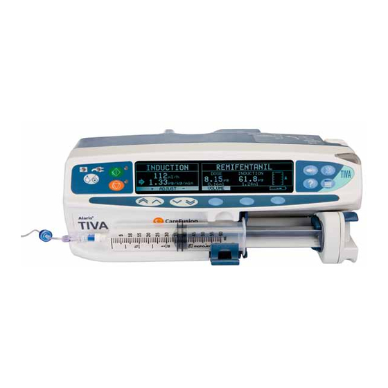
Introduction and Start Up Introduction The IVAC® Syringe Pumps are a range of syringe pumps with features dedicated for use in a variety of areas within a hospital. The range includes these models: The IVAC® P6000 Syringe Pump is a syringe pump suitable for critical care and general infusion applications ... -
Page 5: General Precautions
Introduction and Start Up General Precautions Prior to using this pump, carefully read the Operating Precautions described in the Directions for Use (DFU) This pump contains static-sensitive components. Observe strict precautions for the protection of static sensitive components when attempting to repair and service the pump. An explosion hazard exists if the pump is used in the presence of flammable anaesthetics. -
Page 6: Front Panel, Controls And Indicators
Introduction and Start Up Front Panel, Controls and Indicators Front Panel Front Panel - Model P6000 example Controls and Indicators START Press to start the infusion. The PURGE/ Press to purge the extension BOLUS green LED will flash during set during setup while the infusion. -
Page 7: Main Display
Introduction and Start Up Main Display Model P6000 Infusion Status Syringe Type/Drug Name IVAC 50 Current Time Infusion Rate Pressure Icon VTBI Status Volume Infused VTBI Option Volume Infused Option Model P7000 (Dedicated mode) Infusion Status Drug Name/Protocol Pumping Pressure Infusion Rate Dose Rate Volume Infused... -
Page 8: Loading A Syringe
Introduction and Start Up Loading a Syringe 1. Squeeze the finger grips together on the plunger holder and slide the mechanism to the left. 2. Lift the syringe clamp and rotate to the left. 3. Insert the syringe into the slots on the plunger holder (see Figure 1). For Model TCI & TIVA only - ensure that the Diprifusor tag is positioned towards the display to allow the prefilled syringe tag to be read. -
Page 9: Starting The Pump
Introduction and Start Up Loading a Syringe (continued) Guide to handling the pressure disc 1. Insert the pressure disc into pressure disc support slots as shown in Figure 1. 2. Push pressure disc securely home as shown in Figure 2. Pressure disc support slots Pressure disc Disc recess... -
Page 10: Basic Features
Introduction and Start Up Basic Features Pressure Level Press the button (On Model P7000, press the button). Line pressure occlusion alarm level and current pressure level are shown on a graph. Use the keys to adjust alarm level. Purge/Bolus Press the button. -
Page 11: Backoff Feature
Introduction and Start Up Backoff Feature is a configurable feature, enabled/disabled via the menu, access code . When enabled, BACKOFF CONFIGURATION is automatically activated every time an occlusion occurs. The pump action reverses and pumps backwards to BACKOFF release the pressure which has built up in the infusion system. This minimises the post occlusion bolus. How BACKOFF works When an occlusion occurs, the pump continues pumping until the pressure alarm level is reached and the pump stops. -
Page 12: Chapter 2 Configuration & Calibration
Chapter 2 Configuration and Calibration In this chapter Access Codes Entering an Access Code Dedication Options (901/902) Configuration Options (251) Drug Setup (251) General Options (251) Calibration Procedures Clearing Internal RAM (611) - Page 13 Configuration and Calibration Access Codes The syringe pump software contains a number of configuration and test routines that can be accessed using a technical access code. The majority of routines are 'menu' driven and are accessed by entering a technical access code as shown in the table below.
- Page 14 Configuration and Calibration Dedication Options (901/902) The Mode P7000 pump can be operated in one of two modes: Fully dedicated mode Operating the pump in this mode will remind a user that a pressure disc must be fitted at the start of any infusion. In this mode occlusion pressures are always displayed in .
- Page 15 Configuration and Calibration Drug Setup (251) Drug Setup (Mode TCI & TIVA/Mode TIVA) 1. Enter the access code to display the menu. CONFIGURATION 2. Select using the keys and press the softkey. The drug name list is displayed. DRUG SETUP 3.
- Page 16 Configuration and Calibration Drug Setup (251) (continued) Drug Setup (Mode P6000/Mode P7000) 1. Enter the access code to display the menu. CONFIGURATION 2. Select using the keys and press the softkey. The drug name list is displayed. DRUG SETUP 3. Select the drug name using the keys and press the softkey.
- Page 17 Configuration and Calibration General Options (251) 1. Enter the access code to display the CONFIGURATION MENU 2. Select using the keys and press the softkey. The is displayed: GENERAL OPTIONS GENERAL OPTIONS MENU GENERAL OPTIONS MENU (Mode TIVA/Mode TCI & TIVA) Software version: V3R2 Option Description...
- Page 18 Configuration and Calibration General Options (251) (continued) GENERAL OPTIONS MENU (Mode P6000/Mode P7000) Software version: V3R2 Option Description P6000* P7000* AUTOSAVE Enable/disable Autosave feature (option to retain previous settings when pump is switched on). Enabled: Confirmation is requested at power up to clear or to use previous patient data.
- Page 19 Configuration and Calibration General Options (251) (continued) GENERAL OPTIONS MENU (Mode P6000/Mode P7000) Software version: V3R2 Option Description P6000* P7000* DEFAULT BOLUS Set the default bolus rate value between 10ml/h and 1200 ml/h. CAP BOLUS RATE Set a maximum permissible bolus rate value between 10 ml/h and 1200ml/h. ...
- Page 20 Configuration and Calibration Calibration Procedures The calibration procedure for each of the four sensors within the pumps are described in this section. Calibration is only necessary if in testing, the sensor performs outside of specification or if a full memory clear has been carried out (in which case all calibration stages must be completed).
- Page 21 Configuration and Calibration Calibration Procedures (continued) Linear Pot Calibration (253) Calibration tools required: 0000TG00059 (105mm SPACER) Calibration procedure: Enter the access code Fit calibration tool in position on pump as shown in Steps 1-2 below. At each step is displayed if value is within ...
- Page 22 Configuration and Calibration Calibration Procedures (continued) Beam Occlusion Calibration (717) To convert Kilograms of Force (kgf) to Newtons (N) multiply by 9.806650. For example 10 kgf = 98.07N. ±0.05 Excessive force will damage the plunger mechanism. Do not apply more than 10 kgf to the plunger mechanism at any time.
- Page 23 Configuration and Calibration Calibration Procedures (continued) Line Pressure Calibration (263) P7000 only Calibration tools required: Pressure gauge (Range 0-1400 mmHg) (Tolerance +/- 2mmHg) P7000 Dedicated pressure disc infusion set (for example, G30402) 50ml Luer-lock syringe Calibration procedure: 1.
- Page 24 Configuration and Calibration Calibration Procedures (continued) Line Pressure Calibration (263) P7000 only continued Calibration procedure (continued): 5. Release pressure but do not remove extension set as shown in Step 4. 6. Power down to complete the calibration sequence. Step 3 400mmHg ±...
- Page 25 Configuration and Calibration Clearing Internal RAM (611) Warning: Do not clear the RAM unless absolutely necessary, because all calibration and configuration in the pump will be cleared. If the internal RAM or its associated battery is replaced on the Control PCB, or if the pump fails with an 'ER5 RAM' error it will be necessary to do the following: ...
-
Page 26: Chapter 3 Routine Maintenance
Chapter 3 Routine Maintenance In this chapter Introduction Self-Test Procedure (123) Upgrading Software Event Log Download Teach Learn Linear Speed Test Drive Occlusion Test Line Pressure Test (Model P7000 only) Potential Equalisation Terminal Resistance Test (PE Test) Battery Maintenance Linear Diagnostics Test Physical Inspection and Clean Service Access Options (376) Performance Verification Procedure... -
Page 27: Introduction
Routine Maintenance Introduction For routine maintenance, the following tests and performance verification procedures should be performed in addition to the tasks described in the section 'Physical Inspection and Clean' . Refer to the relevant for the recommended routine maintenance period. Self-Test Procedure (123) The self-test procedure is designed to allow confirmation of many of the pump functions, defaults and calibrations without requiring internal inspection. -
Page 28: Self-Test Procedure
Routine Maintenance Self-Test Procedure (123) (continued) Test Display Description/Action Pumping pressure detection BEAM FORCE : _ . _ _ V Remove the syringe and confirm that the value displayed is within normal range (± 0.05V). Gently press back on the plunger holder and watch the value increase. -
Page 29: Event Log Download
Routine Maintenance Event Log Download A PC application known as the Event Log Download Utility (ELDU) (part number 1000SP00209) is available to download logs from IVAC Syringe Pumps. ® ELDU Operation 1. Click on icon on PC. ELDU 2. Click to agree with Restrictions of Use and continue. -
Page 30: Linear Speed Test
Routine Maintenance Linear Speed Test The linear accuracy of the pump can be verified by measuring the time the plunger holder takes to travel a specified distance. The distance travelled is measured using a dial indicator, mounted in place of the syringe, and the elapsed time can be measured using a stop watch. -
Page 31: Line Pressure Test (Model P7000 Only)
Routine Maintenance Line Pressure Test (Mode P7000 only) The pressure transducer is checked at a number of pressures as indicated in the table below. If the pressure readings displayed appear consistently shifted and outside specification, the sensor may require calibration. Equipment required: Pressure gauge (measuring accuracy +/-2mmHg), or pressure measuring instrument (measuring accuracy +/-2mmHg) with pressure setting facility. -
Page 32: Linear Diagnostics Test
Routine Maintenance Linear Diagnostics Test This test does not represent the linear or volumetric accuracy of the syringe pump. For accurate testing refer to ‘Linear Speed Test’ earlier in this chapter This test should be used as a diagnostic tool only and can assist with the diagnosis of linear speed errors ER1 and ER2. Procedure 1. -
Page 33: Physical Inspection And Clean
Routine Maintenance Physical Inspection and Clean To ensure the pump remains in good operating condition, it is important to keep it clean and carry out the routine procedures described below. All servicing should only be performed by a qualified service engineer. Thoroughly clean external surfaces of the pump, by wiping over with a cloth lightly dampened with warm water and a standard disinfectant/detergent solution. - Page 34 Routine Maintenance Performance Verification Procedure Model / Serial Number: Service Order / Inventory Number: Hospital Name / Reference: Software Version: Inspection Physical inspection and clean Mandatory when serviced UPDATE Fitted Not fitted / Not REF: Applicable Update P7000 with V3R2 software TSM ch3 Update TIVA and TCI &...
-
Page 35: Chapter 4 Troubleshooting
Chapter 4 Troubleshooting In this chapter Introduction Error Codes General Fault Diagnosis... -
Page 36: Troubleshooting
Troubleshooting Introduction Use this troubleshooting guide to help identify the cause of errors and faults which may occur as a result of damage to the pump or failure of an internal component. The following table lists the error codes and describes what action to take to resolve the problem. - Page 37 Troubleshooting Error Codes (continued) Error Failure Action/Replace ER24 POWER SUPPLY VOLTAGE Power supply measurement Check voltage is between 1.5V and 13.5V on PL5-14 on Power PCB MEASUREMENT FAILURE failure and on PL6-14 to IC5 on Control PCB. Replace Power or Control PCBs as necessary. ER25 DISPLAY VIDEO RAM Video RAM fault Reseat/replace Display PCB and/or Control PCB.
- Page 38 Troubleshooting General Fault Diagnosis Parts to Check/Test Fault Dropped or damaged Exposed to fluids No battery power ...
-
Page 39: Chapter 5 Circuit Descriptions
Chapter 5 Circuit Descriptions In this chapter Functional Module Block Diagram Module Overview Functional Description... - Page 40 Circuit Descriptions Functional Module Block Diagram ® IVAC P7000, P6000, TIVA and TCI & TIVA (Mark II) Control PCB Real-time Clock Interfaces Backup RS232/Nurse Battery Call Connector Serial Comms Watchdog TCI Diprifusor Module (TCI & TIVA only) Transmission Backup Speaker TCI Aerial Motor Motor...
- Page 41 CareFusion will make available, on request, circuit diagrams which will assist appropriately qualified technical personnel to repair those parts of the device which are designated by the manufacturer as repairable.
- Page 42 Circuit Descriptions Module Overview Functional Description (continued) Control PCB (continued) LCD Display Drive The LCD display is located on the Display PCB; data is passed using the data bus to a graphics controller located on the Display PCB. Visual Indicators ...
-
Page 43: Chapter 6 Spare Parts Replacement Procedures
Chapter 6 Spare Parts Replacement Procedures In this chapter Introduction Accessing the Pump Lower Case Assembly Battery PSU, Alarm, Mains Inlet Mains On/Off Switch (Mark I) RS232 Connector RS232/Nursecall PCB (Mark I) TCI Diprifusor PCB, PE Stud Connector Pole Clamp Assembly Upper Case Assembly Control PCB, Display PCB Control PCB, Display PCB (continued) -
Page 44: Introduction
manufacturer For fastener torque settings, refer to Appendix C, 'Fitting & Replacement Guidelines' Only use CareFusion recommended spare parts Following all spare part replacement and repair activities, testing must be performed in accordance with the Performance Verification Procedure (PVP), see Chapter 3, 'Routine Maintenance' . -
Page 45: Lower Case Assembly
Spare Parts Replacement Procedures Lower Case Assembly Replacing the lower case 1. To replace a lower case, it will be necessary to fully strip down the old case and insert all the components into the new lower case. This task requires a good knowledge of the pump, so be certain that you are fully conversant with all the procedures in this chapter before undertaking this replacement. -
Page 46: Battery
Spare Parts Replacement Procedures Battery Procedure 1. Disconnect the battery cable from the Power Supply Unit (PSU). 2. Remove the two screws and washers which secure the battery restraining plate. Disconnect earth cable (Model TCI & TIVA only). 3. Remove the restraining plate and foam pad. ) Earth cable ) Earth 4. -
Page 47: Psu, Alarm, Mains Inlet
Spare Parts Replacement Procedures PSU, Alarm, Mains Inlet Procedure 1. Disconnect the grey ribbon cable, the mains inlet connector, the battery connector and the alarm speaker from the PSU PCB. 2. Remove the two screws which secure the mains inlet to the lower case. Slide out the mains inlet assembly and gasket. 3. -
Page 48: Mains On/Off Switch (Mark I)
Spare Parts Replacement Procedures Mains On/Off Switch (Mark I) Procedure 1. Disconnect the mains On/Off switch from the PSU board. 2. Lever out the On/Off switch assembly from the lower case. 3. Reassemble in reverse order. ) Nursecall connector ) Cover ) On/Off switch When refitting, note that the mains On/Off switch assembly is inserted with the OFF rocker topmost, and that the cover is fitted as... -
Page 49: Rs232 Connector
Spare Parts Replacement Procedures RS232 Connector Procedure 1. Remove the four screws which secure the cover plate to the underside of the lower case. Hinge the cover plate open and remove it. 2. Disconnect the RS232 ribbon cable from the Control PCB. 3. -
Page 50: Rs232/Nursecall Pcb (Mark I)
Spare Parts Replacement Procedures RS232/Nursecall PCB (Mark I) Procedure 1. Remove the four screws which secure the cover plate to the underside of the lower case. Hinge the cover plate open and remove it. 2. Disconnect the RS232 ribbon cable from the Control PCB. 3. -
Page 51: Tci Diprifusor Pcb, Pe Stud Connector
Spare Parts Replacement Procedures TCI Diprifusor PCB, PE Stud Connector Procedure 1. Remove the five screws which secure the cover plate to the underside of the lower case. Note: Use star driver to remove fifth screw. Hinge the cover plate open and remove it. 2. -
Page 52: Pole Clamp Assembly
Spare Parts Replacement Procedures Pole Clamp Assembly This instruction applies to the adjustable pole clamp assembly. Procedure 1. Ensure that the hinge is fully open (for access to hinge screws). 2. Remove the two pole clamp screws and washers. 3. Remove the two hinge screws and washers. Remove blanking plate. 4. -
Page 53: Upper Case Assembly
Spare Parts Replacement Procedures Upper Case Assembly Replacing the upper case 1. To replace an upper case, it will be necessary to fully strip down the old case and insert all the components into the new upper case. This task requires a good knowledge of the pump, so be certain that you are fully conversant with all the procedures in this chapter before undertaking this replacement. -
Page 54: Control Pcb, Display Pcb
Spare Parts Replacement Procedures Control PCB, Display PCB Procedure 1. Disconnect the earth cable from the transmission assembly. 2. Remove the five PCB fixing screws and withdraw the Control PCB and Display PCB together. 3. Pull out the four standoffs/pins to separate the Control PCB and the Display PCB. 4. -
Page 55: Control Pcb, Display Pcb (Continued)
Spare Parts Replacement Procedures Control PCB, Display PCB (continued) EPROM socket contact failure could lead to pumps exhibiting errors 5, 25, 35, 36 or 37. Add a new socket if a pump exhibits one of these errors, has a control pcb 6000EL00001 and issues 1 through 12 and the pump was manufactured prior to July 1999 with a serial number within the ranges: 6001-12376 to 6001-14298 6002-10096 to 6002-11583... -
Page 56: Transmission Assembly Removal
Spare Parts Replacement Procedures Transmission Assembly Removal Procedure 1. Remove the four chassis screws and washers and two beam screws which secure the transmission assembly. 2. Disconnect cables and remove the transmission assembly from the upper case. 3. Reassemble in reverse order. ) Beam screws (x2) ) Chassis screws (x3) Washers (x4) ) Transmission Assembly... -
Page 57: Transmission Assembly Breakdown
Spare Parts Replacement Procedures Transmission Assembly Breakdown Bonded Beam 1. Remove nut securing the bonded beam. 2. Reassemble in reverse order. ) Leadscrew seal ring ) Hex nut ) Leadscrew seal Item C (seal ring) is fitted over item D. ) Beam ) Screw/Earth clip/Washer E/F/G... - Page 58 Spare Parts Replacement Procedures Transmission Assembly Breakdown (continued) Leadscrew, Chassis Plate 1. Remove the pin securing the leadscrew gear. Declutch mechanism and pull out leadscrew. 2. Remove the four chassis plate assembly screws. 3. Reassemble in reverse order. ) Leadscrew ) Chassis screws (x2) Washers (x2) ) Chassis plate assembly...
- Page 59 Spare Parts Replacement Procedures Transmission Assembly Breakdown (continued) Motor 1. Remove the circlips and washers securing the two motor idler gears. 2. Disconnect (de-solder) the two motor wires from the flexible circuit. 3. Remove the three mounting plate fixing screws. 4.
- Page 60 Spare Parts Replacement Procedures Transmission Assembly Breakdown (continued) Linear Potentiometer, Motor Flexi Circuit 1. Remove the two motor opto screws securing the motor flexi circuit assembly. 2. Prise the chassis plate cable clip open and remove the transmission flexi cable from the chassis underside. 3.
- Page 61 Spare Parts Replacement Procedures Transmission Assembly Breakdown (continued) Carriage, Outer Tube and Plunger Assembly 1. To breakdown the carriage, outer tube and plunger assembly, refer to the diagrams on the following pages (Figures 1, 2, 3 and 4), removing components as required. 2.
- Page 62 Spare Parts Replacement Procedures Transmission Assembly Breakdown (continued) Carriage, Outer Tube and Plunger Assembly (continued) Figure 2. Transmission Assembly Breakdown Spare Parts Item Description Part Number O RING NITRILE 11.5X1.5 0000ME00277 LEVER TUBE DECLUTCH 1000SP01084 SCREW M3X8 TORX T6 SET PART DOG 1000ME01134 PIN TENSION DIA 2.0X20mm 0000ME00018...
- Page 63 Spare Parts Replacement Procedures Transmission Assembly Breakdown (continued) Carriage, Outer Tube and Plunger Assembly (continued) Figure 3. Transmission Assembly Breakdown Spare Parts Item Description Part Number ASSY FLEXI CIRCUIT MKII TRANSMISSION 7000SP00024 NITRILE ORING 14.1 X 1.6 0000ME00448 BUTTON PLUNGER HOLDER MOULDED 1000ME01114 HOLDER PLUNGER V4 1000ME01059...
- Page 64 Spare Parts Replacement Procedures Transmission Assembly Breakdown (continued) Carriage, Outer Tube and Plunger Assembly (continued) Figure 4. Transmission Assembly Breakdown Spare Parts Item Description Part Number SEAL OUTER TUBE RECESSED 1000ME01121 SEAL RING OUTER TUBE 1000ME01047 PLATE OUTER TUBE SEAL V4 1000ME01022 NITRILE ORING 14.1 X 1.6 0000ME00448...
-
Page 65: Syringe Size Pot, Syringe Clamp
Spare Parts Replacement Procedures Syringe Size Pot, Syringe Clamp Procedure 1. Remove the potentiometer mounting plate fixing screw, remove pin which locks the syringe sizing pot and syringe clamp in place. 2. Slide actuator off the syringe clamp shaft and remove the syringe sizing pot. 3. -
Page 66: Syringe Size Pot, Syringe Clamp (Continued)
Spare Parts Replacement Procedures Syringe Size Pot, Syringe Clamp (continued) Recommended when serviced Bond syringe clamp if the pump was manufactured prior to July 1999 and serial number is within the ranges 6001-00100 to 6001-00972 6002-00100 to 6002-00259 7001-00106 to 7001-04432 Procedure: 1) Remove the two circlips and spirol pin that secure the syringe clamp assembly in the upper case then slide the syringe clamp assembly out through the bush in the upper case. -
Page 67: Aerial Assembly (Model Tci & Tiva)
Spare Parts Replacement Procedures Aerial Assembly (Model TCI & TIVA) Procedure 1. Remove screw which secures aerial assembly. 2. Remove aerial, lift out PCB and aerial wires. 3. Reassemble in reverse order. ) Screw ) Aerial When refitting, ensure aerial wires do not get trapped between PCB and upper case. Spare Parts Item Description... -
Page 68: Pressure Disc Holder (Model P7000)
Spare Parts Replacement Procedures Pressure Disc Holder (Model P7000) Procedure 1. Remove the two lapel labels from the outside of the upper case, as shown in Figure 1. 2. Remove the four assembly fixing screws which secure the pressure transducer holder. 3. -
Page 69: Pressure Transducer (Model P7000)
Spare Parts Replacement Procedures Pressure Transducer (Model P7000) Procedure 1. Remove the two screws and washers securing the pressure transducer. 2. Remove the pressure tranducer and cable connector. 3. Reassemble in reverse order. ) Screws (x2), Washers (x2) ) Pressure sensor connector ) Pressure transducer Spare Parts Item... -
Page 70: Window Display, Keypad
Spare Parts Replacement Procedures Window Display, Keypad Procedure 1. Remove keypad and discard. Keypads cannot be reused. 2. Clean surface where replacement keypad is to be fitted. 3. Fit replacement keypads after removing backing paper from underside. Handle replacement keypads with care to avoid damage ... -
Page 71: Labels
Spare Parts Replacement Procedures Labels Procedure 1. Remove label(s) from case as required. 2. Clean case where replacement label(s) are to be fitted. 3. Fit replacement label(s) as required. Battery label (B4) not shown above, see 'Battery' section GB ENSURE THE SYRINGE IS CORRECTLY LOCATED ES ASEGÚRESE DE QUE LA JERINGA ESTA COLOCADA CORRECTAMENTE SE SE TILL ATT SPRUTAN ÄR RÄTT PLACERAD NL ZORG ER VOOR DAT DE SPUIT CORRECT IS GEPLAATST... -
Page 72: Appendix A Specifications
Appendix A Specifications In this appendix Infusion Electrical Physical Environmental Recycling Electromagnetic Compatibility (Model P7000) - Page 73 Specifications The following information is for reference purposes only. For more detailed specifications refer to relevant DFU. Specifications refer to all models covered by this manual, unless otherwise stated. Infusion Infusion rate range 5ml syringes 0.1ml/h - 150ml/h 10ml syringes 0.1ml/h - 300ml/h 20ml syringes 0.1ml/h - 600ml/h...
- Page 74 Specifications Infusion (continued) Occlusion Pressure Limits for IVAC® 50ml Syringes The following tables show the worst case values for line pressure, time to alarm and bolus volume that can be expected in the event of an occlusion when the IVAC® 50ml syringe is selected, G40020B administration set. Alarm level Rate (ml/h) Maximum time...
-
Page 75: Specifications
Specifications Electrical Battery type Lead acid, rechargeable, sealed. Automatically charges when the pump is connected to AC power. Battery life TCI & TIVA P6000/P7000/TIVA 4h @ 5.0ml/h (20 ºC) 6h @ 5.0ml/h (20 ºC) Battery charging 10 hours from discharge to 80% charge and 24 hours to 100% charge. AC power supply 115-230VAC, 50/60Hz, 20VA (nominal). - Page 76 Specifications Electromagnetic Compatibility (Model P7000) Warning: • The use of any accessory, transducer, or cable with the IVAC® P7000 Syringe Pump other than those specified may result in increased emissions or decreased immunity of the pump. • The IVAC® P7000 Syringe Pump should not be used adjacent to or stacked with other equipment, however if adjacent or stacked use is necessary, the IVAC®...
- Page 77 Note 3—Performed at the Minimum and Maximum Rated Input Voltage. Note 4—CareFusion recommends using signal cables of less than 3 meters in length and this requirement is applicable only if signal cables are 3 meters or more in length. (EN 60601-1-2:2002, Clause 36.202.4) Recommended Separation Distances for LIFE SUPPORT Equipment between portable and mobile RF communications equipment and the IVAC®...
- Page 78 Specifications Electromagnetic Compatibility (Model P7000) continued Guidance and Manufacturer’s Declaration—Electromagnetic Immunity LIFE SUPPORT Equipment The IVAC® P7000 Syringe Pump is intended for use in the electromagnetic environment specified below. The customer or the user of the IVAC® P7000 Syringe Pump should ensure that it is used in such an environment. EN 60601-1-2 Compliance Immunity Test...
- Page 79 Specifications Electromagnetic Compatibility (Model P7000) continued The IVAC® P7000 Syringe Pump is intended for use in an electromagnetic environment in which radiated RF disturbances are controlled. The user of the IVAC® P7000 Syringe Pump can help prevent electromagnetic interference by maintaining a minimum distance between portable and mobile RF communications equipment (transmitters) and the IVAC®...
-
Page 80: Appendix B Spare Parts Listing
Appendix B Spare Parts Listing In this appendix Electrical Components Upper Case Components Lower Case Components Keypad and Labels Transmission Assembly Components Software Test Equipment... - Page 81 Spare Parts Listing Electrical Components Part Number Description 0000EL00004 BATTERY 6V SLA RECHARGE 0000EL00011 CONNECTOR PLUG 16 WAY HEADER 0000EL00106 CONNECTOR PLUG 14 WAY 0000EL00208 BATTERY NiCd 2.4V 40mAH 0000EL00284 LINK FUSE 2A PICOFUSE 0000EL00442 BUZZER PCB P7000 TMB-05 0000EL00450 IC SOCKET 32W-DIL TURNEDPIN 1000EL00135 ASSY CABLE 16 WAY RIBBON...
- Page 82 Spare Parts Listing Upper Case Components Part Number Description 0000ME00002 CIRCLIP E TYPE SHAFT DIA 4.8 0000ME00015 WASHER M3 WAVEY SST 0000ME00045 WASHER M4 WAVEY SST 0000ME00107 ADHESIVE LOCTITE 603 0000ME00116 PIN TENSION DIA 3.0X16MM 0000ME00164 SCREW M2X3 CSK HD SLOTTED 0000ME00189 SCREW M3X12 POZI HD Z+C 0000ME00221...
- Page 83 Spare Parts Listing Lower Case Components Part Number Description 0000ME00015 WASHER M3 WAVEY SST 0000ME00044 FLAT WASHER NYLON M3 TO ISO 7089 0000ME00045 WASHER M4 WAVEY SST 0000ME00141 STUD PE CONNECTOR M6 THREAD x 15 0000ME00189 SCREW M3X12 POZI HD Z+C 0000ME00221 SCREW M3X6 PAN HD POSI ZP+P 0000ME00227...
- Page 84 Spare Parts Listing Keypad and Labels Part Number Description 1000LB00590 INSTRUMENT LABEL 1” X 1 1/2 1000LB01015 LABEL SET END 6000LB00001 LABEL SWITCH PANEL MEMBRANE P6000 MKI 6000LB00003 LABEL SWITCH PANEL MEMBRANE TIVA MKI 6000LB00004 LABEL TCI DIPRIFUSOR 6000LB00008 LABEL FRONT PANEL P6000 MKII 6000LB00009 LABEL FRONT PANEL TIVA MKII 6000LB00010...
- Page 85 Spare Parts Listing Transmission Assembly Components (continued) Part Number Description 0000ME00292 HEX NUT M3 STAINLESS STEEL A4 0000ME00313 SCREW No4x1/4” CSK TRUNCATED POZI SS 0000ME00345 SPRING COMP 8MMX6MM 0000ME00386 SPRING MUSIC WIRE 0000ME00391 WASHER 12X1.6X6.4 I/D NYLON 0000ME00448 NITRILE ORING 14.1 X 1.6 1000ME00097 HALF NUT V4 1000ME00177...
- Page 86 Spare Parts Listing Software Part Number Description 1000SP00209 ASENA SP,KIT,EVENT LOG DOWNLOAD UTILITY 1000SP00529 P6000 V3R2 S/W UPGRADE KIT 1000SP00530 P7000 V3R2 S/W UPGRADE KIT 1000SP00531 P6000 (TIVA) V3R2 S/W UPGRADE KIT 1000SP00532 P6000 (TIVA TCI) V3R2 S/W UPGRADE KIT Test Equipment Part Number Description...
-
Page 87: Appendix C Fitting And Replacement Guidelines
Appendix C Fitting and Replacement Guidelines... - Page 88 Fitting and Replacement Guidelines Torque Guide Always use the correct torque level when making an assembly stage. Take care with the torque applied when re-assembling parts. The head patterns of the fasteners are of the following types: - Pozi Number 1 (smaller X head) - Pozi Number 2 (larger X head) - M3 (Hex head with 5.5mm across flats (AF) drivers)
- Page 89 Fitting and Replacement Guidelines Torque Guide (continued) Pole Clamp Fitting - Setting Adjustable Clamp Established Process Stage Description Component Description Torque Fully loosen locknut with clamp secured 10mm Nylok nut to Lower Case Close clamp Fit and torque 5mm Allen headed bolt 10Nm ...
-
Page 90: Appendix D Configuration & Drug Protocol Records
Appendix D Configured Options and Drug Protocol Records In this appendix Configured Options Record Sheet IVAC® P7000 Syringe Pump Configured Options Record Sheet IVAC® P6000 Syringe Pump Configured Options Record Sheet IVAC® TIVA Syringe Pump Configured Options Record Sheet IVAC® TCI & TIVA Syringe Pump IVAC®... -
Page 91: Configured Options Record Sheet
Configured Options and Drug Protocol Records Configured Options Record Sheet IVAC® P7000 Syringe Pump Enter the pump-specific information for your records on a copy of this page. Software Version: V3R2 Option Range Default Setting FAST START & BACKOFF Disabled/Enabled Enabled SET VTBI OVER TIME Disabled/Enabled Disabled... -
Page 92: Configured Options Record Sheet
Configured Options and Drug Protocol Records Configured Options Record Sheet IVAC® P6000 Syringe Pump Enter the pump-specific information for your records on a copy of this page. Software Version: V3R2 Option Range Default Setting AUTOSAVE Disabled/Enabled Enabled BACKOFF Disabled/Enabled Enabled SET VTBI OVER TIME Disabled/Enabled Disabled... -
Page 93: Configured Options Record Sheet
Configured Options and Drug Protocol Records Configured Options Record Sheet IVAC® TIVA Syringe Pump Enter the pump-specific information for your records on a copy of this page. Software Version: V3R2 Option Range Default Setting BACKOFF Disabled/Enabled Enabled AC FAIL Disabled/Enabled Enabled NEOI WARNING 2 - 10%... -
Page 94: Configured Options Record Sheet
Configured Options and Drug Protocol Records Configured Options Record Sheet IVAC® TCI & TIVA Syringe Pump Enter the pump-specific information for your records on a copy of this page. Software Version: V3R2 Option Range Default Setting BACKOFF Disabled/Enabled Enabled AC FAIL Disabled/Enabled Enabled NEOI WARNING... -
Page 95: Ivac® P7000 Syringe Pump Drug Protocol Setup
Configured Options and Drug Protocol Records P7000, P6000, TIVA, TCI & TIVA 95/106 1000SM00012 Issue 8... -
Page 96: Ivac® Tiva Syringe Pump Drug Protocol Setup
Configured Options and Drug Protocol Records P7000, P6000, TIVA, TCI & TIVA 96/106 1000SM00012 Issue 8... -
Page 97: Ivac® Tci & Tiva Syringe Pump Drug Protocol Setup
Configured Options and Drug Protocol Records P7000, P6000, TIVA, TCI & TIVA 97/106 1000SM00012 Issue 8... -
Page 98: Appendix E Disposal
Appendix E Disposal... - Page 99 If you wish to discard electrical and electronic equipment, please contact your CareFusion affiliate office or distributor for further information.
- Page 100 Disposal Battery Removal continued Removal Procedure 1. Remove the six case retaining screws and washers located on the base of the pump. 2. Carefully separate the upper and lower case halves and disconnect cables. 3. Disconnect the cables from the Control PCB. 4.
-
Page 101: Appendix F Service Contacts
Appendix E Service Contacts... - Page 102 Tel: +31 (0)30 2289 711 Tel: (1) 800 854 7128 Fax: (1) 905-752-3343 Fax: (34) 902 555 661 Fax: +31 (0)30 2289 713 Fax: (1) 858 458 6179 CareFusion Switzerland 221 CareFusion, CareFusion, CareFusion, Sàrl Parc d’affaire le Val Saint Quentin Solbråveien 10 A,...
-
Page 103: Appendix G Document History
Appendix F Document History... - Page 104 8245 Ian Tyler Part number update 2008 August 8628 Ian Tyler Updates identification clarified. 2008 May 2011 11537 Ian Tyler Rebranded to CareFusion Heather June 2012 12424 Admin change Dickhart P7000, P6000, TIVA, TCI & TIVA 104/106 1000SM00012 Issue 8...
- Page 105 Page Intentionally Left Blank...
- Page 106 CareFusion Corporation or one of its subsidiaries. All rights reserved. All other trademarks are property of their respec- tive owners. © 1998-2012 CareFusion Corporation or one of its subsidiaries. All rights reserved. CareFusion Switzerland 317 Sarl, A-One Business Centre, Z.A Vers –La- Pièce n°...
Need help?
Do you have a question about the IVAC P6000 and is the answer not in the manual?
Questions and answers