Table of Contents
Advertisement
Advertisement
Table of Contents

Related Manuals for CareFusion Infant Flow SiPAP


Summary of Contents for CareFusion Infant Flow SiPAP
- Page 1 Infant Flow SiPAP ™ Operator’s Manual...
- Page 2 CareFusion. Information in this document is subject to change without notice. This document is for informational purposes only and should not be considered as replacing or supplementing the terms and conditions of the License Agreement.
-
Page 3: Revision History
Added a warning concerning infant flow consumables. Added the statement “Disconnect the air and oxygen gas sources when the Infant Flow SiPAP is not in use.” Removed Appendix E. February 2009 Changed Ti to T-High and Inspiratory Time to Time High. - Page 4 Infant Flow SiPAP Date Revision Changes (Thigh)” Changed 1 cmH O to 1.5 cmH O; Added “or 60 psi” to clarify 4 bar. Added the parts list for both Infant Flow Products and AirLife Products. Added reference to Cardinal Health contact information on page Added reference to AirLife™...
- Page 5 Updated the part number table. January 2011 Changed the logo and company references to VIASYS. January 2011 Changed the logo and company references to CareFusion. March 2013 Corrected the pneumatic supply range specification. Corrected the atmospheric and environmental storage specification.
-
Page 6: Warranty
One (1) year from date of shipment. The liability of CareFusion Corporation (referred to as the Company) under this warranty is limited to replacing, repairing or issuing credit, at the discretion of the Company, for parts that become defective or fail to meet published specifications during the warranty period;... -
Page 7: Table Of Contents
Infant Flow SiPAP Contents Revision History ......................iii Warranty ........................vi Contents ........................vii List of Figures ......................viii Notices ........................ix Chapter 1 Product Description .................. 1 Chapter 2 Product Specifications ................3 Chapter 3 Summary of Warnings and Cautions ............7 Chapter 4 Unpacking and Setup ................ -
Page 8: List Of Figures
Infant Flow SiPAP List of Figures Figure 1 Stand unpacking and assembly ............11 Figure 2 Stand and Driver assembly ..............12 Figure 3 Driver assembled with patient circuit and /humidifier ......13 Figure 4 Attaching the Abdominal Respiratory Sensor ........14 Figure 5: Flow pressure nomogram for 675-CFG-XXX when used with the Infant Flow variable-flow generator ................ -
Page 9: Notices
Infant Flow SiPAP Notices EMC Notice This equipment radiates and is susceptible to radio frequency energy. If not installed and used in accordance with the instructions in this manual, electromagnetic interference may result. The equipment has been tested and found to comply with the limits set forth in BS EN60601-1-2 for Medical Electrical Equipment Part 1-2: General requirements for safety-collateral standard, Electromagnetic compatibility –... - Page 10 Infant Flow SiPAP Electromagnetic Environment Specifications 675–101–101 Rev. P...
- Page 11 Infant Flow SiPAP 675–101–101 Rev. P...
- Page 12 Infant Flow SiPAP Intended Use Notice The Infant Flow nCPAP System, consisting of the Infant Flow SIPAP Driver and Generator assembly plus NCPAP Prongs and Masks, is intended for the provision of nasal CPAP and BiPhasic CPAP (SiPAP) to produce a sigh. Nasal CPAP should only be used on a spontaneously breathing infant.
- Page 13 Infant Flow SiPAP Declaration of Conformity Notice This medical equipment complies with the Medical Device Directive, 93/42/EEC, and the following Technical Standards, to which Conformity is declared: EN60601-1 and EN60601-1-2 EN 10993 EN 14971 EU Notified Body: BSI (Reg. No. 0086)
- Page 14 Infant Flow SiPAP Infant Flow SiPAP 675–101–101 Rev. P...
-
Page 15: Chapter 1 Product Description
The Comprehensive* configuration offers these features plus a patient triggered BiPhasic mode with apnea backup breaths. The Infant Flow SiPAP driver comes standard in all configurations with an LCD touch screen display, pressure time waveform graphics, integrated patient... - Page 16 Chapter 1 Product Description Battery Backup – Up to 2 hours of battery backup allows for intra-hospital transport. Clear indicators are provided for power supply in use (AC or DC), and battery charge level. Screen Lock – After 120 seconds of no screen inputs, the screen changes to the Locked Screen to prevent inadvertent changes.
-
Page 17: Chapter 2 Product Specifications
Infant Flow SiPAP Chapter 2 Product Specifications Modes • NCPAP • NCPAP with breath rate monitoring and low rate alarm • BiPhasic (time triggered) • BiPhasic (time triggered) with breath rate monitoring and low rate alarm • BiPhasic tr (patient triggered) with breath rate monitoring, low breath rate alarm... - Page 18 Chapter 2 Product Specifications Alarms • High airway pressure – 3 cmH O above measured airway pressure • Airway over-pressure limit alarm • maximum 11 cmH O in NCPAP and time triggered BiPhasic mode • maximum 15 cmH O in patient triggered BiPhasic tr mode •...
- Page 19 Chapter 2 Product Specifications Atmospheric and Environmental • Temperature Range • Operating: 5 to 40° C • Storage: - 20 to 60° C • Relative Humidity -Operating: 0 to 95% non-condensing • Storage: 0 to 95% non-condensing Physical • Dimensions (Driver only) (W x H x D) 26 x38 x 23.5 cm •...
- Page 20 Chapter 2 Product Specifications Infant Flow SiPAP 675–101–101 Rev. P...
-
Page 21: Chapter 3 Summary Of Warnings And Cautions
Warnings • Infant Flow SiPAP driver is intended for use by a trained practitioner, under the direct supervision of a qualified physician. • When the Infant Flow SiPAP driver is connected to a patient, a trained health care professional should be in attendance at all times to react to an alarm or other indications of a problem. - Page 22 SaO2 monitoring. • If the Infant Flow SiPAP driver is shelf mounted, ensure that the driver is stable and that all circuit tubing, hoses and cables are restrained to avoid hazard of toppling.
- Page 23 • Electric shock hazard – Do not remove any of the Infant Flow SiPAP covers or panels. Refer all servicing to an authorized CareFusion service technician or factory trained technician (see Service Manual P/N 675-120).
- Page 24 • If the Infant Flow SiPAP is turned off or if the battery is depleted, the current patient settings will be lost. The Infant Flow SiPAP will return to the default settings when turned back on.
-
Page 25: Chapter 4 Unpacking And Setup
Infant Flow SiPAP Chapter 4 Unpacking and Setup Assembly and physical setup Optional Accessory Figure 1 Stand unpacking and assembly 675–101–101 Rev. P... -
Page 26: Figure 2 Stand And Driver Assembly
Chapter 4 Unpacking and Setup Infant Flow SiPAP Driver Optional Accessory Figure 2 Stand and Driver assembly 675–101–101 Rev. P... -
Page 27: Figure 3 Driver Assembled With Patient Circuit And /Humidifier
Chapter 4 Unpacking and Setup Attaching a patient circuit Infant Flow SiPAP Driver Optional Accessory Figure 3 Driver assembled with patient circuit and /humidifier 675–101–101 Rev. P... -
Page 28: Figure 4 Attaching The Abdominal Respiratory Sensor
Note When the Hudson RCI Humidification System is being used with Infant Flow SiPAP driver, it is recommended that the standard compliance column be used. Attaching the Abdominal Respiratory Sensor Figure 4 Attaching the Abdominal Respiratory Sensor 1. -
Page 29: Figure 5: Flow Pressure Nomogram For 675-Cfg-Xxx When Used With The Infant
Chapter 4 Unpacking and Setup Flow / Pressure Relationship The Infant Flow SiPAP driver is subject to a direct relationship between the controlled enriched gas flow and airway pressure. A nomogram illustrating the relationship between constant airway pressure and flow settings is shown in Figure 5. For... -
Page 30: Figure 6: Flow Pressure Nomogram For 675-Cfg-Xxx When Used With The Infant Flow Lp Or Airlife Variable-Flow Generator
Chapter 4 Unpacking and Setup Flow Pressure Nomogram (for reference only) to show typical flow pressure relationships. This is not meant to establish actual product performance. Figure 6: Flow pressure nomogram for 675-CFG-XXX when used with the Infant Flow LP or AirLife variable-flow generator Individual devices have a tolerance of up to ±15 percent from that illustrated in the nomogram and, in particular, at pressures below 2cmH... - Page 31 Chapter 4 Unpacking and Setup User Verification Test WARNING Do not attach Generator to the patient until User Verification and initial setup into NCPAP mode is complete. CAUTION Although failure of any of the user verification tests described in this section will not prevent the ventilator from functioning, the ventilator should be checked to make sure it is operating correctly before use on a patient.
- Page 32 E55 displays, and measured FiO displays as dashes. WARNING! When the Infant Flow SiPAP unit is connected to a patient, and the internal oxygen monitor is disabled, the Infant Flow SiPAP unit must be used with an external oxygen monitor.
- Page 33 Chapter 4 Unpacking and Setup Leak Test Have the patient circuit and generator assembled as shown in Figure 3. Connect the patient interface (prong or mask) to the generator (see Chapter 5, Step by Step Fixation) and occlude the opening to the patient. If not powered up already, switch on the power to the driver.
- Page 34 Chapter 4 Unpacking and Setup Alarms Test WARNING Prior to patient application, ensure that all User Verification testing and calibration procedures are successfully completed. User Verification testing and calibration procedures must be done off patient. NOTE The audible and visual alarm indicators run automatically on power up of the driver and allow the audible and visual alarms to be checked.
- Page 35 Chapter 4 Unpacking and Setup Perform the Alarms Test on the Infant Flow SiPAP driver using the following steps and the initial settings provided above. Make appropriate connections for air and oxygen gas supply. Connect power cord to appropriate AC outlet. Attach patient circuit, generator and patient interface (mask or prong) as shown in Figure 3.
- Page 36 Chapter 4 Unpacking and Setup Infant Flow SiPAP User Verification Test Checklist Driver Serial Number:_____________________ Test Date:_________________ TEST PASS FAIL Automated Tests Power On Check Manual Tests Two Point O Sensor Calibration Patient Circuit Leak test Manual Alarms Checks Low Airway Pressure Alarm...
-
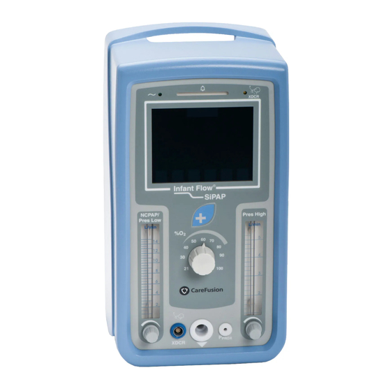
Page 37: Chapter 5 Operation
Infant Flow SiPAP Chapter 5 Operation Front Panel Indicators and Controls The front panel consists of a LCD touch screen display with key pad, separate flow meter controls for adjustment of NCPAP /Pres Low and Pres High and a %O blender control. -
Page 38: Figure 8 Rear Panel
Chapter 5 Operation Rear Panel Figure 8 Rear Panel 675–101–101 Rev. P... - Page 39 Chapter 5 Operation Table 1 Soft-key operation Description Example A button which is enabled. A button which is inhibited due to non-availability of the designated feature or pending acknowledgement of an active alarm condition. A selected mode or control pending confirmation is visually highlighted and intermittently flashes between yellow and white text.
- Page 40 Chapter 5 Operation Changing a Control When a control such as Time-High is selected, increase and decrease buttons appear. The control and the displayed value for the selected parameter are highlighted. Use the decrease or increase keys to adjust the parameter. You may accept the action by pressing the control button again.
- Page 41 Chapter 5 Operation Parameter Default Value on Change of Mode Some controls are active in more than one operating mode. In these instances, there is a separate default value for operating modes as illustrated with the following table. Settings that are changed by the operator in one specific mode will be maintained if the mode is changed to another mode within the same mode group.
-
Page 42: Figure 9 Setup Screen
Chapter 5 Operation User Interface Display Screen Displays Setup Screen – The Setup screen prompts the user to confirm settings for base line pressure level (NCPAP / Pres Low), %O , upper level pressure (Pres High) controls and confirmation of connection of the Transducer Interface (XDCR) to the driver. -
Page 43: Figure 10 Alarm Set/Confirm Screen
Chapter 5 Operation Alarm set/confirm Screen Figure 10 Alarm set/confirm Screen Touch the NCPAP button or the Alarm Mute / Reset button for 3 seconds to set the alarms and to move to the next screen. If either button is not touched within 2 minutes, the alarm limits will be set automatically. - Page 44 Chapter 5 Operation Mode Select Screen - Here the operator can select the desired mode of operation. Once selected, the operator has the ability to adjust the screen controls for the mode selected. Only the relevant controls available for the selected mode are visible.
- Page 45 Chapter 5 Operation Monitored Parameter Screen – This screen is accessed by pressing the change screen button. The monitored parameters screen displays measured values and control settings. Adjustments to controls active for the currently selected mode are possible from this screen. To return to the main screen press the screens button again.
- Page 46 Do not attach Generator to the patient until User Verification and initial set up into NCPAP mode is complete. Patient interfaces from CareFusion accommodate a wide range of patients. Application of an incorrectly sized prong, mask or bonnet will affect stability of the generator.
- Page 47 Directions for Use. (The AirLife Infant nCPAP system is only available in the United States and Canada.) WARNING! CareFusion consumables are specifically designed to be used with Infant Flow Drivers and are the only consumables validated for use with Infant Flow devices.
- Page 48 Chapter 5 Operation Infant Flow SiPAP 675–101–101 Rev. P...
-
Page 49: Chapter 6 Operating Modes
Infant Flow SiPAP Chapter 6 Operating Modes NCPAP The Nasal CPAP mode can be enabled to have breath rate monitoring displayed (NCPAP +Apnea Mode, or NCAP +LBR Mode), or the system can operate without having the breath rate monitoring displayed (NCPAP Mode). Breath rate monitoring requires the use of the Transducer Assembly (part number 677-002) and the Abdominal Respiratory Sensor (part number 467349). - Page 50 Chapter 6 Operating Modes BiPhasic tr* The BiPhasic tr mode allows for patient triggered pressure assists with breath rate monitoring enabled, adjustable apnea time interval, apnea alarm and adjustable apnea back up rate. The upper level pressure is delivered based on operator set Time High (T-High) and pressure settings.
-
Page 51: Chapter 7 Alarms And Indicators
Infant Flow SiPAP Chapter 7 Alarms and Indicators Audible and visual indications are given to alert the Operator to specified conditions that affect operation. The electronic alarm limits are automatically set after two minutes without the necessity of Operator inputs. - Page 52 Chapter 7 Alarms and Indicators Alarm Types The following alarm systems are provided with the Infant Flow SiPAP driver. Electronic alarms are set after 2 minutes of operation without operator intervention although the operator can manually set or reset them if required. Refer to Appendix C for information on troubleshooting alarms.
-
Page 53: Figure 18 Flat Battery Screen
Figure 18 Flat Battery screen Operation without Electrical Power (No AC or DC power) The Infant Flow SiPAP will continue to deliver NCPAP flow only as set from the NCPAP / Pres Low flow meter and the set %O in the event of a total loss of AC and DC power. - Page 54 Chapter 7 Alarms and Indicators Alarm Symbols and Indicators The following displays are shown within the graphical display. As needed displays in this table are shown separately as Domestic US configuration displays (left-hand column) and non-US configuration displays (right-hand column). Table 1 Alarm Symbols and Indicators Indicator Meaning...
- Page 55 Chapter 7 Alarms and Indicators Indicator Meaning Indication during pre-use checks that operator should attach the respiratory sensor (cross indicates that transducer assembly is not connected) Indication during pre-use checks that the operator should attach the respiratory sensor (indicates that transducer assembly is connected) Does not verify attachment of sensor to patient Refer to manual...
- Page 56 Chapter 7 Alarms and Indicators Indicator Meaning Display of measured airway pressure graph. With breath monitoring active, spontaneous breaths are indicated in yellow, below delivered airway pressure graph. Device fault (fault code will be indicated). Refer to manual. Contact qualified service technician. Note Provision of labeling in this manual for any function should not be taken as evidence that the function is available.
-
Page 57: Chapter 8 Maintenance And Cleaning
CAUTION Do not immerse any part of the Infant Flow SiPAP driver in water or sterilize it with gas or steam. To prevent liquid from entering the unit, do not spray cleaning solution on the exterior surface of the unit. - Page 58 Chapter 8 Maintenance and Cleaning Storage and Battery Care Store the unit in a clean dry location. Make sure that all connections and ports are suitably covered to prevent the ingress of dirt, moisture and foreign objects. If the unit is not being used for a long period of time, remove the battery (refer to the Service Manual or your Service Technician).
-
Page 59: Chapter 9 Explanation Of Symbols
Infant Flow SiPAP Chapter 9 Explanation of Symbols Equipment Symbols The following symbols may be referenced on the Infant Flow SiPAP driver or in accompanying documentation. Table 1 Equipment Symbols Source / Meaning Symbol Compliance Symbol #03-02 I Indicates ATTENTION, consult ACCOMPANYING... - Page 60 Meaning Symbol Compliance ISO 15223:2000 (3.11) Operating temperature range of unit EN 980:2003 (5.7.3) 2.5A/T 250 V Fuse holder and fuse rating CareFusion Transducer Assembly Symbol XDCR IEC 60878:1988 (01-41) Alarm ISO 7000:2004 (2301) IEC 60878:1988 Type BF patient applied part...
- Page 61 Chapter 9 Explanation of Symbols Source / Meaning Symbol Compliance Keep Away from Heat ISO 15223:2000 (3.8) Symbols used on buttons The following symbols are used to label user input areas within the graphical display. As needed displays in this table are shown separately as Domestic US configuration displays (left-hand column) and non-US configuration displays (right-hand column).
- Page 62 Chapter 9 Explanation of Symbols Symbol Description Nasal CPAP mode Nasal CPAP mode with breath rate monitoring BiPhasic mode BiPhasic mode with breath rate monitoring BiPhasic tr* mode with breath rate monitoring Manual Breath. Single BiPhasic cycle at current settings for T-High, Pres High and % O .
-
Page 63: Appendix A Product Configurations
Infant Flow SiPAP Appendix A Product Configurations Non-US Configuration Parameters Table 2 Non-US Configuration Parameters Parameter Accuracy Units Default Set Oxygen concentration, %O ±3 NCPAP / Pres Low flow rate L/min ±15% Pres High flow rate L/min ± 15% BiPhasic / BiPhasic tr* on time, T- seconds .3 sec... - Page 64 Appendix A Product Configurations Infant Flow SiPAP 675–101–101 Rev. P...
-
Page 65: Appendix B Pneumatic Diagram
Infant Flow SiPAP Appendix B Pneumatic Diagram 675–101–101 Rev. P... - Page 66 Appendix B Pneumatic Diagram Infant Flow SiPAP 675–101–101 Rev. P...
-
Page 67: Appendix C Alarm Troubleshooting
Infant Flow SiPAP Appendix C Alarm Troubleshooting Table 4 Alarm Troubleshooting Alarm Priority Possible Cause Actions < 18% High • O calibration • Restore FiO level to above the required. minimum limit • Press Alarm Reset for 3 seconds. • Recalibrate O as soon as practicable. -
Page 68: Figure 15 Ncpap
Appendix C Alarm Troubleshooting Alarm Priority Possible Cause Actions Battery fault High (Cannot be • Battery • Push Alarm Mute button for 3 reset) disconnected seconds to silence alarm • Battery failing to • Refer to Service Technician. hold charge Low battery Medium •... - Page 69 Appendix C Alarm Troubleshooting Alarm Priority Possible Cause Actions Low breath High • Rr = 0 for > low • Push Alarm Mute button once to rate breath (apnea) silence alarm • Plus: audible / interval timeout visual alarms • Restore patient breathing. only •...
- Page 70 Appendix C Alarm Troubleshooting Infant Flow SiPAP 675–101–101 Rev. P...
-
Page 71: Appendix D Fault Management
Infant Flow SiPAP Appendix D Fault Management The general philosophy when handling a software detectable fault condition is to still allow a basic level of treatment to be applied to the patient - with over pressure protection, oxygen alarms and apnea monitoring (where possible), but inhibiting the higher level features of the unit (such as BiPhasic modes). - Page 72 Appendix D Fault Management Control Modes and Measurements Features Impact On Unit Reporting Functionality Mechanism Software restarts, Spurious and status bar software Spurious extended mode () () () exception (minor) alternates with trapped worst error code High-priority alarm;...
- Page 73 Appendix D Fault Management Clas- Software Corrective Fault condition Consequence sification Response Action Required Unable to User lockout: Non-volatile retrieve/set unit Service: Fix or Unusable Error "E##" memory fault configuration and replace PCB prompt calibration data Service: Low User lockout: Calibration data Sensor readings level calibration...
- Page 74 Appendix D Fault Management Clas- Software Corrective Fault condition Consequence sification Response Action Required Oxygen sensor High priority Oxygen sensor No oxygen Service: Fix fault (ADC hits alarm; Error readings invalid monitor sensor/circuits. rail) "E##" prompt Oxygen sensor User: Check gas Possible fuel cell, cannot be High priority...
- Page 75 Appendix D Fault Management Clas- Software Corrective Fault condition Consequence sification Response Action Required Spurious Hardware software reinitialized Software Software: Fix interrupt, XTAL (disabled) with interrupted and fails, stack Spurious alarm bar lit and persistent restarts (possibly overflow/underflo beeper sounding exceptions during treatment) w, CPU Class B...
- Page 76 Appendix D Fault Management Infant Flow SiPAP 675–101–101 Rev. P...
-
Page 77: Glossary
Infant Flow SiPAP Glossary Term Meaning Apnea Temporary inability to breathe. Low Breath Rate Breaths per minute (applies to each of spontaneous, triggered and mandatory) CPAP Continuous Positive Airway Pressure Generator Patient attachment for delivering CPAP, used with nasal prongs or mask BiPhasic Time triggered, time cycled pressure assists at two separate pressures levels. - Page 78 Infant Flow SiPAP 675–101–101 Rev. P...
-
Page 79: Index
Infant Flow SiPAP Index fixation, 32 Flat Battery alarm, 39 front panel, 23 Absominal Respiratory Sensor, 14 Fully integrated alarm package, 1 Accessories, 2 airway pressure, 15 alarm priority, 37 Alarm set/confirm Screen, 29 gas flow, 15 Alarm Symbols, 40... - Page 80 Index silence active alarms, 37 Silencer / Bacterial Filter, 5 Parameter Adjust Screen, 30 Soft-key operation, 25 parameter default values, 27 specifications, 3 ® Patented Infant Flow Generator, 1 Storage, 44 patient circuit, 13 Supply Gases Failure alarm, 38 physical specifications, 5 symbols, 45 Pneumatic Diagram, 51 pneumatic supply, 4...
Need help?
Do you have a question about the Infant Flow SiPAP and is the answer not in the manual?
Questions and answers