
Related Manuals for CareFusion M675


Summary of Contents for CareFusion M675
- Page 1 Service Manual ® Infant Flow SiPAP Model M675 © Copyright 2004, VIASYS Healthcare Critical Care 675-120 Revision C November 2004...
- Page 2 ® Infant Flow SiPAP 675-120 Revision C November 2004...
-
Page 3: Revision History
Service Manual Revision History Date Revision Pages Changes September 2003 675-120(1) Release November 2004 Release manual in VIASYS Healthcare template using VIASYS Healthcare Critical Care nomenclature. December 2004 Title page, 19, Revised per EO 27980. 30, 39, 45, 50, Removed the picture from the title page. 56, 57, 61, 62, Deleted the ESD warning from page 19. -
Page 4: Contact And Ordering Information
® Infant Flow SiPAP Contact and Ordering Information United States, Latin America, Asia Pacific: Sales, Service and Clinical Support: VIASYS Healthcare Critical Care Division 22705 Savi Ranch Parkway Yorba Linda, CA 92887 Phone: (714) 283-8444 (800) 381-3552 Fax: (714) 283-8493 www.VIASYShc.com United Kingdom: Sales, Service and Clinical Support:... -
Page 5: Warranty
Service Manual Warranty ® The Infant Flow SiPAP is warranted to be free from defects in material and workmanship and to meet the published specifications for One (1) year from date of shipment. The liability of VIASYS Healthcare, Critical Care Division, (referred to as the Company) under this warranty is limited to replacing, repairing or issuing credit, at the discretion of the Company, for parts that become defective or fail to meet published specifications during the warranty period;... -
Page 6: Table Of Contents
® Infant Flow SiPAP Contents Revision History..................3 Contact and Ordering Information ............4 Warranty ....................5 Limitation of Liabilities ....................5 Contents ....................6 Notices ....................8 Copyright Notice ......................8 Trademark Notices ......................8 EMC Notice ........................8 MRI Notice........................ -
Page 7: Service Manual
Service Manual Preparing and Connecting the Equipment..............36 Setting Up the Equipment.................... 40 Setting the NCPAP Parameters................... 41 Setting the BiPhasic Parameters ................. 42 Setting the Triggered BiPhasic Parameters..............43 Calibration........................44 Giving a Manual Timed Sigh..................45 Operation Without Electrical Power ................45 Fault Indications...................... -
Page 8: Notices
® Infant Flow SiPAP Notices Copyright Notice Copyright © 2004 VIASYS Healthcare, Critical Care Division, California. This work is protected under Title 17 of the U.S. Code and is the sole property of the Company. No part of this document may be copied or otherwise reproduced, or stored in any electronic information retrieval system, except as specifically permitted under U.S. -
Page 9: Mri Notice
Service Manual With regards to Electrical Safety: Class 1 equipment Contains type BF patient applied parts Continuous Operation MRI Notice This equipment contains electromagnetic components whose operation can be affected by intense electromagnetic fields. Do not operate this device in a MRI environment or in the vicinity of high-frequency surgical diathermy equipment, defibrillators, or short-wave therapy equipment. -
Page 10: Yorba Linda, Ca
® Infant Flow SiPAP Declaration of Conformity Notice This medical equipment complies with the Medical Device Directive, 93/42/EEC, and the following Technical Standards, to which Conformity is declared: Council Directive(s): MDD 93/42/EEC Annex II (excluding section 4) Safety: EN 60601-1, EN 794-1 EMC: EN 60601-1-2:2001 Conformity Assessment: MDD Annex II Quality System: ISO 13485... - Page 11 Service Manual 675-120 Revision C November 2004...
-
Page 12: Chapter 1 - Product Description
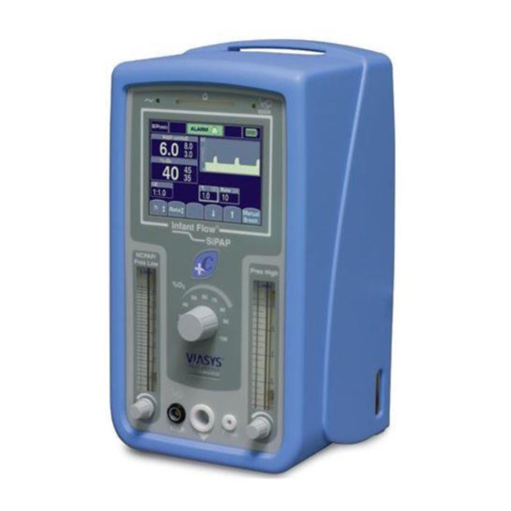
® Infant Flow SiPAP Chapter 1 - Product Description ® The Infant Flow SiPAP is a non-invasive form of respiratory support designed for use in hospital environments such as Neonatal and Pediatric Intensive Care Units. It can also be used when transporting patients within the hospital environment. ®... - Page 13 Service Manual Screen Lock - After 120 seconds of no screen inputs, the screen changes to the Locked Screen to prevent inadvertent changes. Upon activation of a high priority alarm the screen changes to an unlocked state to allow for immediate interventions as required.
-
Page 14: Chapter 2 - Product Specifications
® Infant Flow SiPAP Chapter 2 - Product Specifications Modes • NCPAP • NCPAP with breath rate monitoring and low rate alarm • BiPhasic (time triggered) • BiPhasic (time triggered) with breath rate monitoring and low rate alarm • BiPhasic tr (patient triggered ) with breath rate monitoring, low breath rate alarm, and apnea back up Controls •... -
Page 15: Alarms
Service Manual Alarms • High airway pressure – 3 cmH20 above measured airway pressure • High circuit pressure – maximum 11 cmH20 in time triggered Biphasic mode • High circuit pressure – maximum 15 cmH20 in patient triggered Biphasic tr* mode •... -
Page 16: Atmospheric & Environmental
® Infant Flow SiPAP Atmospheric & Environmental • Temperature Range-Operating: 5 – 40° C • Storage: 0 - 50° C • Relative Humidity -Operating: 0 – 90% non-condensing • Storage: 0 – 90% non-condensing Physical • Dimensions (driver only)-(W x H x D) 26 x38 x 23.5 cm / 10.25 x15 x 9.25 in •... - Page 17 Service Manual 675-120 Revision C November 2004...
-
Page 18: Chapter 3: Summary Of Warnings And Cautions
® Infant Flow SiPAP Chapter 3: Summary of Warnings and Cautions ® Please review the following safety information prior to operating the Infant Flow SiPAP. Attempting to operate this equipment without fully understanding its features and functions may result in unsafe operating conditions. Warnings and Cautions, which are general to the use of the device under all circumstances, are included in this section. - Page 19 Service Manual • When filling a humidifier, do not move the stand. Moving or transporting the stand while refilling may cause the stand and equipment to over balance. • Do not use conductive patient circuits with the Infant Flow SiPAP Driver. •...
-
Page 20: Cautions
® Infant Flow SiPAP Cautions • Federal Law (USA) restricts this device to sale by or on the order of a physician. • The precision gas blender in this product may become non-functional or damaged if used without the protective water trap and filters provided. •... - Page 21 Service Manual 675-120 Revision C November 2004...
-
Page 22: Chapter 4: System Construction
® Infant Flow SiPAP Chapter 4: System Construction CAUTION Where the integrity of the external protective earth conductor is in doubt the equipment shall be powered by its internal power source (battery). The IFSD is AC powered with an integral rechargeable DC battery that provides power for up to two hours without any interruption of performance or function. - Page 23 Service Manual Figure 1 - IFSD Front Panel Gas Module The function of the gas module is to take air and oxygen, blend them into the required mixture and deliver this mixture to the patient at the prescribed flow rate. The gas module also measures the oxygen concentration, measures the patient pressure, provides an auxiliary gas outlet (optional) and provides switched Biphasic flow.
- Page 24 ® Infant Flow SiPAP Electronics Module The function of the electronics module is to power the unit either by AC mains supply or DC emergency battery supply, to control the gas module and read the gas module sensors. The main components are a power supply unit, a rechargeable battery, a main processor PCB, LED PCB, Valve/Sensor PCB and a LCD screen (touch screen).
- Page 25 Service Manual Figure 3 -IFSD Internal Components 675-120 Revision C November 2004...
-
Page 26: Touch Screen
® Infant Flow SiPAP Front Panel Module The function of the front panel module is to house the gas and electrical connections to the patient, Operator controls and indicators. The module consists of a front panel plate, the touch screen with key pad, flowmeters and FiO control, patient connectors and indicators and an ambient light sensor. -
Page 27: Alarm Conditions
Service Manual alarm condition, the button is solid yellow with an audible alarm. If any alarm condition resets itself, the yellow alarm bar remains to alert the clinician of a previous problem. Caution/Information The Caution/Information icon alerts the Operator to read this manual. It flashes during an alarm condition. -
Page 28: Diagnostic Screen
® Infant Flow SiPAP • an audible Whistle which sounds a constant tone when the gas imbalance limits are exceeded. • an audible Alarm which sounds a constant tone or two different intermittent tones; medium or high level (medium level sounds beep.beep.beep every 15 seconds and high level sounds beep.beep..beep beep beep every 10 seconds). - Page 29 Service Manual Table 2 – Diagnostic Screen Boxes Description DIPS The DIPS box shows the position of the DIP switches on the main processor PCB. Position 1 is on and O is off. CONTRAST The contrast indicator box is for use in the factory for setting the screen INDICATOR contrast.
-
Page 30: Chapter 5 - Operation
® Infant Flow SiPAP Chapter 5 - Operation Gas Flow With the oxygen and air connections connected and the power switched on, oxygen and air at 386 kPa (56 psig) flows to the blender. The air passes through a water trap with an integral filter where any moisture in the air is removed. - Page 31 Service Manual Figure 6 - IFSD Gas Flow Schematic The patient pressure is shown on the touch screen and is monitored by a pressure sensor which sends the signal to the main processor. A zeroing valve automatically checks the pressure readings against atmospheric pressure to ensure accuracy of the patient pressure readings.
-
Page 32: Electronic Functions
® Infant Flow SiPAP WARNING The NCPAP Pres high must be adjusted to zero when not required for the patient. Triggered BiPhasic For BiPhasic Tr, a micro controller provides reliable indications of breaths derived from the patient abdominal respiratory sensor. It sends signals to operate the NCPAP Pres high valve to provide a timed sigh. -
Page 33: Electrical Layout
Service Manual Figure 7 - IFSD Electronic Enclosure Electrical Layout Figure 8 shows the electrical wiring and PCB connector layout. Figure 8 - IFSD Electrical Wiring Diagram 675-120 Revision C November 2004... -
Page 34: Fault Management
® Infant Flow SiPAP Fault Management When a software detectable fault condition occurs, the unit still allows a basic level of treatment to the patient. Table 4 shows the fault conditions and the level of control available. Table 4 - Faults, Available Modes and Control Functions Measurements Software Control Modes NCPAP+... - Page 35 Service Manual 675-120 Revision C November 2004...
-
Page 36: Chapter 6 - Operation
Service Manual Chapter 6 - Operation The operating procedures below show the procedures for all models. Reference should only be made to the procedures for the model in use. Read the Warnings and Cautions at the beginning of this manual before you start the procedures. Preparing and Connecting the Equipment WARNING Ensure the whistle sounds during gas connection, if not the device may be... - Page 37 Service Manual Figure 9 - Patient Connections WARNING Check that the water trap is empty before use and empty it frequently during use. 675-120 Revision C November 2004...
- Page 38 ® Infant Flow SiPAP Make sure that the water trap is empty. If necessary, empty any water from the trap (refer to Chapter 3, Maintenance). Gas Flow Pressure Setting The IFSD provides a virtually constant airway pressure irrespective of patient demand or expiratory flows via the specially designed generator and nasal prongs.
- Page 39 Service Manual Switching On the IFSD WARNING Do not attach the Generator to the patient until the initial set up is complete. Put the power switch on the back panel to the position. • the warning bar comes on • the green power light remains on •...
-
Page 40: Setting Up The Equipment
® Infant Flow SiPAP Setting Up the Equipment The procedures show the screen set up for all modes. If a mode is not applicable to the model in use, go to the next applicable step. Adjust the NCPAP Pres low flowmeter to indicate the required flow rate. When done, touch the flashing button to confirm the initial setting The button icon changes to a... -
Page 41: Setting The Ncpap Parameters
Service Manual When the alarm limits have been set, the screen changes to the Mode Selection Screen and defaults to the nCPAP mode. • the alarm limits are set Touch NCPAP, NCPAP+Apnea, BiPhasic, BiPhasic+Apnea, or BiPhasic Tr to enter the Parameter Set up Screen for each mode. Note When the Mode Selection screen is showing, NCPAP treatment will always be delivered. -
Page 42: Setting The Biphasic Parameters
® Infant Flow SiPAP Note If a high priority alarm occurs, the key pad automatically unlocks. To return to the Mode Selection Screen, touch the button. Setting the BiPhasic Parameters For BiPhasic+Apnea function the transducer interface and the abdominal respiratory sensor must be connected. -
Page 43: Setting The Triggered Biphasic Parameters
Service Manual Parameters Ti and Rate can now be adjusted. Note The I/E rate changes accordingly. To return to the Mode Selection Screen, touch the button. Note The button is shown with a pink background if an alarm condition occurs. If this occurs, the button cannot be operated until the alarm condition has been cleared or silenced using the alarm button. -
Page 44: Calibration
® Infant Flow SiPAP Confirm the BiPhasic Tr settings by touching the flashing BiPhasic Tr button. When the settings have been accepted, the screen changes to the locked screen and treatment starts. To adjust the parameters, touch the button. The screen changes to the BIPHASIC TR Adjust Screen. Parameters Ti, Rb and Tapnea can now be adjusted. -
Page 45: Giving A Manual Timed Sigh
Service Manual Touch the button. The screen returns to the Start Up Screen . Note If the calibration procedure fails, a red is shown in the applicable button. Re- calibrate and if necessary, replace the O fuel cell. Giving a Manual Timed Sigh In the Mode Select or Adjust screens of NCPAP+Apnea, BiPhasic+Apnea or BiPhasic Tr - touch the button to give the patient a manual timed sigh. - Page 46 ® Infant Flow SiPAP • the alarm bar comes on and the predominant fault code number is shown in the status bar If an error code is shown, refer to the Service Manual or contact your Service Engineer to rectify the faults. Over Pressure Indications If an over pressure occurs, the software opens the dump valve to release the pressure.
- Page 47 Service Manual Indications and Method of Resetting Alarm Method of Setting Actions or Canceling High oxygen concentration Set automatically on Intermittent high level Push the Alarm (> 5 FiO above set point entering NCPAP Button once to stop Audible Alarm. at time alarm is set for 15 mode for the first time the Audible Alarm for...
- Page 48 ® Infant Flow SiPAP Indications and Method of Resetting Alarm Method of Setting Actions or Canceling Low pressure Set automatically on Intermittent high level Push the Alarm (< 2 cmH O below set entering NCPAP Audible Alarm. Button once to stop point for 15 seconds) mode for the first time the Audible Alarm for...
- Page 49 Service Manual Indications and Method of Resetting Alarm Method of Setting Actions or Canceling Low battery voltage Automatically Intermittent medium Push the Alarm (< 10 V for 5 seconds). constantly monitored level Audible Alarm. Button once to stop with the power switch the Audible Alarm for Warning Bar flashes in the on position with...
- Page 50 ® Infant Flow SiPAP Indications and Method of Resetting Alarm Method of Setting Actions or Canceling Software not running with Automatic Constant Audible Cannot be reset. unit connected to power Alarm. Refer to Service Warning Bar on. Engineer. Screen displays flashing fault code (E number).
- Page 51 Service Manual Indications and Method of Resetting Alarm Method of Setting Actions or Canceling Low breath rate Set automatically on Intermittent high level Push the Alarm (Rr = 0 for > breath rate entering BiPhasic Tr, Audible Alarm. Button once to stop timeout as determined by NCPAP + Apnea or the Audible Alarm for...
-
Page 52: Diagnostics
® Infant Flow SiPAP Diagnostics Diagnostic mode is accessed by enabling DIP switch 6 and exited by disabling it. Enable DIP switch 6 during Start Up, Adjust or Mode Selection. The screen changes to the Diagnostics Menu Screen (for a description of the displayed information refer to paragraph 1.2.5): •... - Page 53 Service Manual Figure 11 – Security Screen To return to the Diagnostics Menu Screen, touch the button. Select to carry out a valve test The diagnostic main screen stays the same and the key pad layout changes. Touch the first key to test the zero valve, the second key to test the dump valve and the third key to test the PA valve.
- Page 54 ® Infant Flow SiPAP Table 6 - Error Codes Error Software Corrective Fault Condition Consequence Response Action Code Program memory Unusable – Software Hardware held in Reload checksum error. corrupt, execution permanent reset software. inhibited. condition with Warning Bar on. Battery too discharged Unusable - no user Hardware held in...
- Page 55 Service Manual Error Software Corrective Fault Condition Consequence Response Action Code Charged battery voltage No backup – battery Battery fault icon Replace too low (<11 V) when capacity low. flashes and ‘Error battery or under test load. number’ alarm charger. prompt.
- Page 56 ® Infant Flow SiPAP Error Software Corrective Fault Condition Consequence Response Action Code Zero valve activation fault Unusable – pressure User lockout Replace the (via sense). sensor readings ‘Error number’ pneumatics unreliable. prompt. PCB and re- calibrate O and pressure sensors.
- Page 57 Service Manual Error Software Corrective Fault Condition Consequence Response Action Code Oxygen sensor calibrates Unusable – oxygen User lockout Replace the but the fuel cell is worn out sensor readings ‘Error number’ fuel cell (low gain). unreliable. prompt. and re- calibrate the sensor.
- Page 58 ® Infant Flow SiPAP Error Software Corrective Fault Condition Consequence Response Action Code E90* Spurious software Spurious – software Hardware Replace the interrupt, XTAL fails, stack interrupted and restarts reinitialized main control overflow/ underflow, CPU (possibly during (disabled) with PCB and re- Class B exception.
- Page 59 Service Manual 675-120 Revision C November 2004...
-
Page 60: Chapter 7- Maintenance
Service Manual Chapter 7- Maintenance Cleaning CAUTION Do not immerse any part of the IFSD in water or sterilize it with gas or steam. Clean the exterior surfaces of the IFSD and the transducer interface with a mild soap or liquid disinfectant solution. Do not use cleaning agents that contain abrasives. -
Page 61: Maintenance Frequencies
Service Manual Numbers in parenthesis in the Removal/Fitting procedures are the item numbers on the associated figure. Lubricate new O-rings before installation with grease, Krytox 240AC before installation. Maintenance Frequencies Table 7 shows the recommended frequencies for replacement of components. Table 7 - Maintenance Frequencies Component Replacement Frequency... -
Page 62: Removal And Fitting Of Case
® Infant Flow SiPAP Removal and Fitting of Case Refer to Figure 12. Removal Remove the ten screws (1) on the rear panel. Pull off the case (2). Fitting Install the case (2) over the main frame, making sure that all wires and pipes are secure and cannot be trapped by the case. - Page 63 Service Manual Disconnect the battery lead connector SK3 (1) (cable 5) from the plug PL3 on the Main Processor PCB. Remove the screw (2) on the rear panel and remove the spacer (3) complete with compression pad. Pull the battery (4) complete with lead from the compartment. Note The battery is held in position in the compartment by up stands (5) on the frame.
- Page 64 ® Infant Flow SiPAP Figure 13 - Battery Removal/Fitting 675-120 Revision C November 2004...
-
Page 65: Removal And Fitting Of Oxygen Filter
Service Manual Removal and Fitting of Oxygen Filter Note This procedure can be done without removing the case. Refer to Figure 14. Removal Remove the banjo screw (1) on the end of the air/oxygen mounting block (2). Remove the filter (3). Remove and discard the O-ring (4). -
Page 66: Removal And Fitting Of Fuel Cell Filter/Restrictor
® Infant Flow SiPAP Removal and Fitting of Fuel Cell Filter/Restrictor Refer to Figure 15. Removal Remove the case . Remove the oxygen filter screw (1) from the flow mixer block (2). Remove the filter/restrictor (3). Remove and discard the O-ring (4) and the O-ring (5) from the oxygen filter screw (1). -
Page 67: Removal And Fitting Of The Fuel Cell
Service Manual Removal and Fitting of the Fuel Cell Refer to Figure 16. Removal Remove the case. Disconnect the connector SK12 (1) from the top of the fuel cell. If necessary, remove the screw (2) securing the C clip (3) and release the C clip securing the cable (cable 7) and the ferrite. -
Page 68: Removal And Fitting Of Blender And Components
® Infant Flow SiPAP Figure 16 - Fuel Cell Removal/Fitting Removal and Fitting of Blender and Components Refer to Figure 17. Removal Remove the case. Remove the battery. Disconnect the connector SK1 (1) on the LED PCB. Disconnect the connector SK5 (2) on the Main Processor PCB. Disconnect the connector at PL5 (3) on the Patient Trigger PCB. - Page 69 Service Manual Remove the Valve/Sensor PCB (13) as follows: Disconnect the fuel cell connector SK1 (14) at PL1 on the Valve/Sensor PCB. Disconnect the dump/vent valve connector SK3 (15) at PL3 on the Valve/Sensor PCB. Remove the five screws (16). Pull the Valve/Sensor PCB (13) downwards and out forward to disconnect the PCB from the D plug PL2.
- Page 70 ® Infant Flow SiPAP Figure 17 - Blender and Components Removal/Fitting Fitting Fit new pilot drive check valves as follows: Fit the seat (28), a duckbill check valve (26), the guide (27), the second duck bill check valve into the cylinder (23). Hold the nut (25) and tighten the cylinder body (23).
-
Page 71: Removal And Fitting Of Water Trap Filter
Service Manual Fit the Valve/Sensor PCB (13) to the D plug PL2. Fit the five screws (16). Connect the fuel cell connector SK1 (14) at PL1 on the Valve/Sensor PCB. Connect the dump/vent valve connector SK3 (15) at PL3 on the Valve/Sensor PCB. -
Page 72: Removal And Fitting Of Case Bleed Filtered Restrictor
® Infant Flow SiPAP Removal and Fitting of Case Bleed Filtered Restrictor Refer to Figure 18. Removal Remove the case. Remove the case bleed filtered restrictor (3) from the pipe. Discard the case bleed filtered restrictor (3). Fitting Install the new case bleed filtered restrictor (3). Screw on the water trap bowl (1) and tighten using the Special Spanner. -
Page 73: Removal And Fitting Of Pa Solenoid Valve
Service Manual Removal and Fitting of PA Solenoid Valve The PA Solenoid Valve is replaced by replacing the Valve/Sensor PCB Removal Remove the case. Remove the Valve/Sensor PCB. Fitting Install the new Valve/Sensor PCB. Carry out an Oxygen Leak check (see Appendix A)and functional check of the IFSD and calibrate the fuel cell. -
Page 74: Testing
® Infant Flow SiPAP Click on the Download button. The download takes approximately 1 minute at 57600 bps. When the download is complete, the audible alarm on the IFSD stops and the unit enters the normal operational mode. Disconnect the Download Cable from plug PL4 on the Main Processor PCB. Refit the case. -
Page 75: Chapter 8 - Explanation Of Symbols
Service Manual Chapter 8 – Explanation of Symbols ® The following symbols may be referenced on the Infant Flow SiPAP driver or in accompanying documentation Symbol Source / Compliance Meaning Indicates ATTENTION, consult ACCOMPANYING Symbol #03-02 IEC 60878 DOCUMENTS Symbol #5016 IEC 60417 This symbol indicates a FUSE. - Page 76 ® Infant Flow SiPAP Symbol Source / Compliance Meaning Operating temperature range of unit Warning Bell VIASYS Healthcare Symbol VIASYS Healthcare Symbol Respiratory Connection and Indicator This symbol indicates TYPE B equipment, which indicates equipment that provides a particular Symbol # 5333 IEC 60417 degree of protection against electric shock, particularly with regards to allowable leakage Symbol #02-03 IEC 60878...
-
Page 77: Symbols Used On Buttons
Service Manual Symbols used on buttons The following symbols are used to label user input areas within the graphical display. As needed displays in this table are shown separately as Domestic US configuration displays (left-hand column) and International configuration displays (right-hand column). - Page 78 ® Infant Flow SiPAP Nasal CPAP mode with breath rate monitoring BiPhasic mode BiPhasic mode with breath rate monitoring BiPhasic Tr mode with breath rate monitoring Manual Breath. Single breath cycle at current settings for Ti, NCPAP Pres high and O %.
-
Page 79: Appendix A- Oxygen Leak Test
Service Manual Appendix A- Oxygen Leak Test Oxygen Leak Test This test will check for leaks within the enclosure. Test equipment needed: Calibrated oxygen analyzer 1. Connect the driver to the air and oxygen supplies. Use adaptors to couple to the customer-specified gas block on the driver. - Page 80 ® Infant Flow SiPAP 6. Set the pressure High Flow Meter to about 2 LPM then push its softkey button under the right flowmeter icon. 7. The Respiratory Sensor option is not required, but to finish, select this soft key button. 8.
- Page 81 Service Manual 10. Accept the default BiPhasic settings by selecting the BiPhasic soft key again (Figure 4). Figure 4 11. Verify that the measured value doesn’t exceed 23% FiO2. If so, then troubleshoot for an oxygen leak. Check all the fittings and connections and repeat the Oxygen Leak Test (Figure 5).
-
Page 82: Appendix B- Product Configurations
® Infant Flow SiPAP Appendix B- Product Configurations Non-US Configuration Parameters Parameter Accuracy Units ±3 Set Oxygen concentration, %O ±15% CPAP flow rate L/min ± 15% Bi-level additional flow rate L/min ± 0.005 BiPhasic on time, Ti (inspiration time) 3.0 * seconds ±... -
Page 83: Appendix C - Spare Parts
Service Manual Appendix C - Spare Parts To identify a part referenced in this manual, refer to the associated Figure and Item number in Table 8. Table 8 - Spare Parts Figure Item Number Part Name Part Number Battery 777244 Filter 467464 O-ring, 7/16”... -
Page 84: Additional Service Parts
® Infant Flow SiPAP Additional Service Parts Part Number Description 467472 KNOB GREY 6MM SHAFT (LOW FLOWMETER) 467468 CAP PLAIN GREY OD29 467471 POINTER GREY OD29 467469 KNOB GREY 3/16 SHAFT (HIGH FLOWMETER) 467470 CAP PLAIN GREY OD15 675-308 CASE 467467 FOOT, POLYURETHANE .5OD 467466... - Page 85 Service Manual Part Number Description 675-300 EXHAUST TUBE 90 DEGREE 675-101 OPS MAN INF FLOW SiPAP 677-002 TRANSDUCER INTERFACE 467349 ABDOMINAL RESP SENSOR 25PK B03895 VALVE CHECK DCKBL BLACK 467464 FILTER NYLON CONE INL 467269 FILTER ELEMENT (WATERTRAP) 777235 POWER SUPPLY MK3 467455 SWITCH COVER 675-256...
- Page 86 ® Infant Flow SiPAP 675-120 Revision C November 2004...
-
Page 87: Glossary
Service Manual Glossary Term Meaning Temporary inability to breathe; monitoring of breathing (non-US Apnea labeling) Breaths per minute (applies to each of spontaneous, triggered and mandatory) Bytes per second Centimeters of Water (Pressure) CPAP Continuous Positive Airway Pressure Fraction of Inspired Oxygen Patient attachment for delivering CPAP, used with nasal prongs or Generator mask... - Page 88 ® Infant Flow SiPAP Term Meaning Sigh A single pulse of additional gas flow Apnea Interval (non-US labeling) or Low Breath Rate (LBR) monitor alarm time (US-labeling); both in seconds apnea This mnemonic may also be associated with an alarm icon Machine breath inspiration time (seconds) Application of NCPAP, BiPhasic, BiPhasic Tr, with or without Treatment...
Need help?
Do you have a question about the M675 and is the answer not in the manual?
Questions and answers