Sign In
Upload
Manuals
Brands
Sutter Instrument Manuals
Laboratory Equipment
P-1000
Sutter Instrument P-1000 Manuals
Manuals and User Guides for Sutter Instrument P-1000. We have
1
Sutter Instrument P-1000 manual available for free PDF download: Operation Manual
Sutter Instrument P-1000 Operation Manual (104 pages)
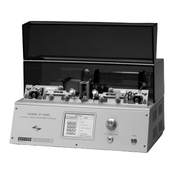
Flaming/Brown Micropipette Puller System
Brand:
Sutter Instrument
| Category:
Laboratory Equipment
| Size: 4 MB
Table of Contents
Disclaimer
5
Safety Warnings and Precautions
5
Electrical
5
Avoiding Electrical Shock and Fire-Related Injury
5
Back Injury Prevention
6
Operational
6
Handling Micropipettes
6
Table of Contents
7
1 General Information
13
Introduction
13
Glass Capillary & Heating Filament Specifications
13
Glass Capillary
13
Heating Filament
13
Technical Support
14
System Description - Front Panel
14
Figure 1-1. P-1000 Front Panel
14
System Description - Mechanical (Puller Anatomy)
15
Some Basic Information
15
Air Cooling System
15
Figure 1-2. P-1000 Base Plate with Components Detail
15
Heating Assembly
16
Figure 1-3. Filament Block Assembly
16
Figure 1-4. Heat Sensor Location on Filament Block Assembly
16
Upper Pulley Assembly
17
Figure 1-5. Upper Cable Pulley Assembly
18
Cabinet
19
Electronics
19
2 Touchscreen User Interface Guide
21
Startup Screen
21
Figure 2-1. Startup Screen
21
Figure 2-2. Startup Fault Report Screen
21
Home Screen
22
Opening a Program
22
Calibration of Touch Screen
22
Pulling a Pipette
22
Figure 2-3. Home Screen
22
Figure 2-4. Pulling a Pipette
23
Figure 2-5. Pull Report
24
Figure 2-6. View the Pull Report
24
Pull Report
24
View Pull Results
24
Figure 2-7. Ramp Test
25
Figure 2-8. Ramp Test Result
25
Ramp Test
25
Menu Screen
26
Set Time & Date
26
Lock Program
26
Preheat Jaws 70°C (Thermolock™)
26
Air before Pull
26
Figure 2-9. Menu Screen
26
Figure 2-10. Setting Time and Date
26
Air after Pull
27
Program List
27
Sutter Pipette Cookbook Feature
27
Figure 2-11. Program List
27
Editing a Program
28
Installing a Program
29
Figure 2-12. Single Line Looped Program
29
Figure 2-13. Two-Line Program with First Line Looped
29
Patch Pipettes
30
Microinjection Pipettes and High Resistant Electrodes (30-300 Megohm)
30
Lock/Unlock Program
30
Figure 2-14. Locking & Unlocking a Program (Menu Screen)
30
Safe Heat Mode
31
Time & Delay Modes of Cooling
31
Figure 2-15. Items that Cannot be Changed in a Locked Program
31
Figure 2-16. Time Mode of Air-Cooling
31
Jaw Temperature
32
Figure 2-17. Delay Mode of Air-Cooling
32
Figure 2-18. Jaw Temperature
32
Edit User Notes
33
Error Messages During Pull
33
Figure 2-19. Edit User Notes
33
3 Installation
35
Unpacking
35
Setting up
35
Line Power (Mains)
35
Figure 3-1. P-1000 Cabinet (Rear View), Detailing Power Entry Module, Fuse-Holder, Fuse, and Spare Fuse Holder
36
Figure 3-2. P-1000 Cabinet (End View, Left), Showing Power Switch
36
4 Operating Instructions
37
First Time Use
37
Quick Start Instructions
37
Figure 4-1. Startup Screen
37
Figure 4-2. Home Screen
37
Figure 4-3. Using the Knob or Keypad to Select a Program
38
Figure 4-4. Instruction to Run Ramp Test
38
Figure 4-5. Running the Ramp Test
39
Figure 4-6. Ramp Test Screen
39
Figure 4-7. Loading a Piece of Glass
40
Figure 4-8. Using the PULL Button to Start the Ramp Test
40
Figure 4-9. Selecting a Ramp Value
41
Figure 4-10. Identifying the Installed Ramp Value
41
Figure 4-11. Using the Installed Ramp Value for Heat
42
Figure 4-12. Pressing PULL on Front Panel to Start the Ramp Test
42
Figure 4-13. Cycling through a Looped 1-Line Program
43
Figure 4-14. Brief Display of Pull Results
43
Figure 4-15. Making a Different Type of Pipette Using the Sutter Cookbook
44
Figure 4-16. Placing Puller into Safe Heat Mode
44
Default Configuration
45
Figure 4-17. Obtaining Help Information
45
Table 4-1. Standard Factory Configuration
45
Programs
47
Program Structure
47
Program Line Pull Cycle Parameters
48
Figure 4-18. Examining the Contents of a Program Using the Program Edit Screen
48
Pull Cycle
50
Start up
50
Figure 4-19. Home Screen
50
Figure 4-20. Examining the Contents of a Program Using the Program Edit Screen
51
Editing a Program
52
Editing Tips
52
Edit User Notes
52
Figure 4-21. Program List Screen
52
Figure 4-22. Edit User Notes
53
Menu Screen
54
General
54
System Options
54
Program Options
54
Figure 4-23. Menu Screen
54
Ramp Test
55
Figure 4-24. Ramp Test Ramp Value Screen
55
Heat Value Recommendations
56
Pulling Pipettes
56
Procedures
56
Figure 4-25. Pull Report
56
Figure 4-26. Sample Program
57
Figure 4-27. Pull Cycle Report (Multiple-Loops)
57
Notes on Program Operation
58
Parameter Adjustment
58
General Information
58
Micropipette/Microinjection Needle Fabrication
58
Heat
58
PULL Strength
59
VELOCITY (Trip Point)
59
TIME Mode (Cooling)
59
Delay Mode (Cooling)
60
PRESSURE Adjustment
60
Filament Width
60
Patch Pipette Fabrication
60
Heat
61
PULL Strength
61
VELOCITY (Trip Point)
61
Cooling
61
Pressure
62
Thermolock™ Pre-Heat Mode
62
Step-By-Step Patch Pipette Programming
65
Technical Tips for Pulling Micropipettes
66
Regulating the Time It Takes to Pull a Sharp Pipette
66
Heat
66
Pipette Position
67
Regulating the Length and Tip Size of a Sharp Pipette
67
Heat
67
Filament Width
67
Air Flow
67
DELAY Mode of Active Cooling
67
Fire Polishing
68
Figure 4-28. Side View of Fire Polishing Spacer
68
Heating Filaments
69
General Information
69
Filament Positioning and Aligning
69
Figure 4-29. Fire-Polish Spacer in Puller Bar
69
Figure 4-30. Filament Alignment
69
Box Filament
70
Positioning
70
Figure 4-31. End View of Box Filament and Glass
70
Geometry
71
Trough Filament
71
Figure 4-32. Box Filament Positioning
71
Figure 4-33. End View of Trough Filament and Glass
71
Table 4-2. Box Filament Sizes
71
Figure 4-34. Trough Filament Positioning
72
Geometry
72
Positioning
72
Table 4-3. Trough Filament Sizes
72
5 Maintenance
73
Cleaning
73
Heating Filament Replacement
73
Filament Replacement (Step by Step)
73
Air Jet Position
73
Positioning the Filament in Relation to the Glass Capillary
73
Figure 5-1. V-Groove Bearings and Puller Bars
73
Figure 5-2. Filament Alignment
74
Pulley Adjustment
75
Figure 5-3. Micropipette Shapes
75
Regeneration of Drierite Granules
76
Removing the Canister
76
Replacing the Granules
76
Figure 5-4. Pulley Adjustment
76
Reinstalling the Canister
77
6 Troubleshooting
79
Controlling Pipette Tip Shapes
79
Problem: What Type of Glass Should be Used
79
Problem: the Resistance of Pulled Pipettes Is too Low. How Can a Higher-Resistance Pipette be Pulled
79
Problem: How Can Tips be Made Even Smaller
79
Problem: How Can the Size of a Patch-Pipette be Increased
80
Problem: Patch-Pipette Tips Vary in Size from Pull to Pull
80
Problem: Difficulty Making an Injection Pipette with a 0.5 - 1 MM Tip that also Has a very Short Final Taper and Tip (20 to 50 MM Long). How Can this be Done
80
Problem: the Electrodes Are Bent. How Can They be Made to Pull Straight
80
Problem: One Electrode Is Much Longer than the Other Electrode
80
Problem: the Shape and Resistance of the Pipette Changes from Pull to Pull
81
System Operation/Function Problems
81
Startup Problems
82
General Operational Problems
82
On-Screen Emergency Reset Messages
82
Table 6-1. Startup Problems Troubleshooting
82
Table 6-2. General Operational Problem Troubleshooting
82
Table 6-3. On-Screen Emergency Reset Messages
82
On-Screen Error Messages (Edit/Pull Screen)
83
Table 6-4. On-Screen Error Message in Edit/Pull Screen When Ramp Value Is Not Specified
83
Table 6-5. On-Screen Error Messages in Edit/Pull Screen When PULL Is Pressed
84
Table 6-6. Other On-Screen Error Messages in Edit/Pull Screen
84
Diagnostics
85
Figure 6-1. Starting Diagnostics from the Main Menu Screen
85
Figure 6-2. Diagnostics Screen
85
Air Pressure Amount ("Pressure Dialed In")
86
Air Pressure Transducer Reading
86
Air Pump Test ("Run the Pump Unregulated 1 Sec.")
86
Automatic Pressure On/Off
86
Air Valve ("Open/Close the Air Valve")
86
Figure 6-3. Air Pressure System Diagnostics Screen
86
Test for Air Leaks
87
Trace and Correct Leaks
87
Air Pressure System
86
Figure 6-4. Heat System Diagnostics Screen
87
Heat Diagnostics
87
Figure 6-5. Heat System Diagnostics Error Reporting
88
Figure 6-6. Pull Diagnostics Screen
88
Pull Diagnostics
88
Figure 6-7. Velocity Diagnostics Screen
89
Velocity Diagnostics
89
Touchscreen Calibration
90
Technical Support
90
Figure 6-8. Starting Calibrate Touchscreen from the Main Menu Screen
90
Figure 6-9. Touchscreen Calibration
90
Appendix A. Limited Warranty
91
Appendix B. Accessories
93
Filaments
93
Capillary Glass Tubing
93
Other Accessories
93
Appendix C. Fuse Replacement
95
Figure 6-10. Power Entry Module and Fuse Holder
95
Appendix D. Technical Specifications
97
Appendix E. Drierite Material Safety Data Sheet
99
Index
101
Advertisement
Advertisement
Related Products
Sutter Instrument P-97
Sutter Instrument P-2000
Sutter Instrument P-30
Sutter Instrument Lambda 10-3
Sutter Instrument LAMBDA 10-B
Sutter Instrument Lambda DG-4
Sutter Instrument Lambda DG-5
Sutter Instrument LB10-3
Sutter Instrument MP-225
Sutter Instrument MP-225A
Sutter Instrument Categories
Laboratory Equipment
Amplifier
Control Systems
Controller
Work Light
More Sutter Instrument Manuals
Login
Sign In
OR
Sign in with Facebook
Sign in with Google
Upload manual
Upload from disk
Upload from URL