Table of Contents
Advertisement
Advertisement
Table of Contents

Related Manuals for Risco ProSYS series


Summary of Contents for Risco ProSYS series
- Page 1 Installation and Programming Manual ProSYS version 7.xx...
-
Page 2: Ce Declaration Of Conformity
For the CE Declaration of Conformity please refer to our website: www.riscogroup.com. Compliance Statement Hereby, RISCO Group declares that the ProSYS series of control panels and accessories are suitable for use in systems designed to comply with: EN50131 Grade 3, Environmental Class II EN50136 Series;... -
Page 3: Table Of Contents
Table of Contents CHAPTER 1 INTRODUCING PROSYS ..........................5 SYS? ................................5 HAT IS SYS ................................6 NSTALLING ..................................6 BOUT SYS A ........................9 RCHITECTURE AND APABILITIES SYS F ................................10 EATURES CHAPTER 2 MOUNTING AND WIRING THE MAIN PANEL ..................16 1: M .......................... - Page 4 Table of Figures 1: P SYS A ......................9 IGURE RCHITECTURE AND APABILITIES 2: LCD K ................................12 IGURE EYPAD 3: M ..........................16 IGURE OUNTING THE ANEL 4: M ..........................18 IGURE ANEL IRING IAGRAM 5: 4-W BUS .............................19 IGURE XPANSION 6: Z ..........................21 IGURE ONNECTION...
-
Page 5: Chapter 1 Introducing Prosys
Chapter 1 Introducing ProSYS This chapter provides a basic introduction to the ProSYS system and its architecture and capabilities, as described in the following sections: ♦ What is ProSYS?, below ♦ Installing ProSYS, page 6 ♦ About Wire, page 6 ♦... -
Page 6: I Nstalling P Ro Sys
Installing ProSYS This ProSYS Installation and Programming Manual details how to install the ProSYS hardware and to program the ProSYS Main Panel, as described in the following main steps: ♦ Step 1: Mounting the Main Panel (Chapter 2) ♦ Step 2: Wiring the Main Panel (Chapter 2) ♦... - Page 7 For maximum system stability, it is best NOT to exceed a total of 300 meters (1000 feet) of wire when wiring the Expansion BUS. For a distance of more than 300 meters, refer to RISCO Group’s customer support service for detailed information.
- Page 8 Total Desired Wire Gauge in Particular Branch Auxiliary Power 32/02 mm 28/02 mm 24/02 mm 16/02 mm 7/02 mm 18 AWG 19 AWG 20 AWG 22 AWG 24 AWG (Max Current Draw per Max Run Max Run Max Run Max Run Max Run Branch) Meters...
-
Page 9: P Ro Sys A Rchitecture And C Apabilities
ProSYS Architecture and Capabilities The following diagram provides an overview of the ProSYS's architecture and capabilities. Examine this figure before beginning your ProSYS installation to obtain an overall picture of the full extent of the ProSYS system's capabilities. Figure 1: ProSYS Architecture and Capabilities ProSYS Installation and Programming Manual... -
Page 10: Prosy Feature
ProSYS Features This section describes the features of the ProSYS system, including features specific to each ProSYS model. Feature-Specific Limitations Each ProSYS model has several feature-specific limitations, as described in the following table: Feature ProSYS 16 ProSYS 40 ProSYS 128 Total Zones 8-16 8-40... -
Page 11: Zone Expansion
Main Panel The Main Panel is the foundation of the system's operation and has the following features: ♦ 8 basic hardwired zones ♦ 6 Utility Outputs: 1 x relay (programmable output) (3 Amps) 1 x 500mA transistor (Open Collector) 4 x 70mA transistors (Open Collector) ♦... - Page 12 ♦ Super heterodyne technology ♦ Programmable supervision time ♦ Tamper detection ♦ Low battery in transmitters detection ♦ Signal jamming indication ♦ Programmable supervision time Partitions/Areas ♦ Up to 8 independent partitions/areas ♦ Any zone can be assigned to any partition/area ♦...
- Page 13 User Codes and Authority Levels ♦ 1 engineer code ♦ 1 sub engineer code ♦ 1 Grand Master code ♦ Up to 99 user codes (ProSYS 128) ♦ 8 Authority levels ♦ Double code option for high security ♦ Codes can be defined to 4 or 6 digits (By default 6 digits) Programmable Utility Outputs ♦...
- Page 14 a pre-recorded Event announcement. You can then acknowledge the event and remotely operate the system. ♦ Remotely operating the system, which includes: O Partition arming and disarming O Zone bypassing O UO activation/deactivation O Changing Follow-Me numbers O Performing Listen and Talk options that enable you to listen in to your property and talk back, if necessary Power Supply Expansion Module Although the ProSYS's Main Panel provides 600mA of auxiliary power (900mA for Bell), the...
-
Page 15: False Alarm Reduction
Printer Module A Printer module, designed to interface between the ProSYS's 4-wire Expansion BUS and a Centronics-type parallel printer, enables the printing of all significant system events as they occur, including access control activities, if applicable. Each event includes the date, time and if applicable, the affected partition and the user involved. -
Page 16: Chapter 2 Mounting And Wiring The Main Panel
Chapter 2 Mounting and Wiring the Main Panel This chapter covers the first two steps of the ProSYS installation procedure, as follows: Step 1: Mounting the Main Panel, below Step 2: Wiring the Main Panel, page 18 Step 1: Mounting the Main Panel The ProSYS Main Panel . -
Page 17: Safety Precautions
Safety Precautions When mounting the Main Panel, the following safety precautions are relevant: When the Main Panel is powered on, mains voltage is present on the main PCB. To prevent risk of electric shock, disconnect all power (AC transformer and battery) and phone cords before servicing. - Page 18 Step 2: Wiring the Main Panel This step explains the various wiring and connection procedures that must be performed when wiring the Main Panel, as follows: Wiring the Main Panel, page 18 Wiring the Zones to Sensors and Detectors (Zone Terminals Z1 through Z8), page 19 Wiring the Auxiliary Devices, page 22 Wiring the Bell Sounders, page 23 Wiring the Bell Tamper, page 23...
- Page 19 The second set of four terminals on the left of the Main Panel represent the Expansion BUS. These support the connection of keypads and expansion modules. The connections are terminal-to-terminal with color-coded wires, as follows: Description Terminal AUX RED +12V power for BUS expansion modules COM BLK Black 0V common for BUS expansion modules BUS YEL...
- Page 20 NOTES: It is recommended that you use an End-of-Line Resistor at the far end of each hardwired zone to prevent short-circuits (16 resistors are supplied). For a zone with a tamper switch, you can use a Double End-of-Line Resistor to save additional Main Panel connections (refer to Figure 6 on page 21).
- Page 21 Connections on Zone Expanders (ProSYS EZ8, ProSYS EZ16): Figure 6: Zone Connection Diagrams ProSYS Installation and Programming Manual...
- Page 22 The following table indicates the EOL limit values when the ProSYS panel detects a status difference. Please respect the EOL standard values given in the installation manual to prevent unexpected alarms. Zone Type Zone Mode Impedance (KΩ) 47.1<R Ready R<47.1 Trip 6.97<R Trip...
-
Page 23: Wiring The Bell Tamper
NOTES: The total power from the AUX terminals should not exceed 600mA. To connect a 4-wire smoke detector or devices that require resetting after an alarm condition, connect the Auxiliary power AUX and UO terminals (refer to Figure 4 on page 18, for smoke detector wiring). - Page 24 Wiring the Box Tamper To wire the box tamper: Connect the box tamper to the BOX TMP and COM terminals on the Main Panel, as Figure 4 illustrated in on page 18. Refer also to the diagram shown below. Figure 7: Wiring the Box Tamper Wiring External Triggerable Devices To wire external triggerable devices: Wire the external triggerable devices that you want to activate to the outputs UO1-UO6, as...
- Page 25 Connecting the J10 Connector Figure 8: Connecting the J10 Connector The J10 connector (jumper) determines the UO1 connection (behavior), which is normally used for an external siren connection, as follows: Positive (POS): When the J10 connector is placed on POS, the C terminal on UO1 receives 13.8V.
- Page 26 Connecting to Ground (Earth) To connect to ground (earth): Connect the metal box and the door of the metal box to mains earth (ground), as shown in the diagrams on the following page. Refer also to What Makes a Good Ground?, page 17. IMPORTANT: Connecting to ground must be performed according to the local National Electrical Code.
-
Page 27: Jumper Settings
Jumper Settings The ProSYS is equipped with internal jumpers. Use the following table to configure the jumpers according to the desired configuration. Jumpers Function siti Enables to default the panel and restore the ProSYS codes (Grand master, installer and sub installer) to the manufacturers default settings. -
Page 28: Connecting Ac Power
Jumpers Function siti Determines the UO1 connection (behavior), see Connecting the J10 Connector, page 25. UO1 (J10) Default: 1 PIN Connectors Connector Function J1, J5 BUS 1 Plug in connector. BUS 2 Plug in connector. SIG In connector. The J4 SIG IN voice connector enables the transfer of audio data between the Voice module RP200VC and the phone line. -
Page 29: Chapter 3 Installing External Modules And Devices
Chapter 3 Installing External Modules and Devices This chapter describes steps 3 to 5 of the ProSYS installation procedure, as follows: Step 3: Identifying and Wiring Keypads and Expansion Modules Step 4: Adding Modules, page 31 Step 5: Applying Power, page 35 Step 3: Identifying and Wiring Keypads and Expansion Modules This section explains how to program a unique ID number to identify each keypad and... - Page 30 Installing a Keypad NOTE: For information on installing the Touchscreen keypad, refer to the ProSYS Touchscreen Keypad Instruction manual that is included with the product. To install a keypad: 1 Open the Keypad Cover: Remove the back of the keypad cover, and using a screwdriver, press in each of the retaining clips to separate the back cover from the keypad.
- Page 31 4 Set the Tamper Switch: Before mounting the keypad on the wall, locate the rear-mounted Tamper Switch and make sure that it is vertically oriented. Replace the Cover: O Carefully replace the keypad's printed circuit board in its cover. O Join the cover and base by hooking the tops together and then snapping the bottom in place, returning the retaining clips to their positions.
- Page 32 Wiring Utility Output Modules Figure 15: Utility Output Module UO4 (Showing an Example of UO4 Wiring) Figure 16: Utility Output Module E08 Figure 17: Utility Output Module X-10 To wire Utility Output modules: 1 Set the Dip Switches: Assign a unique ID to each Utility Output expansion module by setting the dip switches, using on page 29.
- Page 33 O Connect one (or more) normally open (NO) momentary-action pushbutton switches in a series between the TAMP and COM terminals in order to short-circuit these terminals while the cabinet door is closed. NOTES: It is not necessary to use a tamper switch if another module sharing the same cabinet is equipped with one.
- Page 34 Wiring Power Supply Expansion Modules (PS LED) (UO LED) 1 2 3 4 1 2 3 4 (Battery Jumper) BELL/LS (Bell/Loudspeaker Jumper) Battery (Over Current LED) Connections BELL TAMP BELL LS Loudspeaker/ Bell Transformer Power to Accessories and Detectors Figure 18: 1.5A Power Supply Module PS Figure 19: 3A Power Supply Module PS To wire Power Supply expansion modules: 1 Set the Dip Switches: Assign a unique ID to each Power Supply expansion module...
- Page 35 O Use a larger wire gauge if the distance separating the siren and the module is significant. Take the siren(s) current draw into account as well when selecting a wire gauge (refer to the table of gauge sizes in Chapter 1, Introducing ProSYS). NOTE: Any internal siren(s) connected to the Power Supply expansion module will operate exactly like the siren(s) connected to the Main Panel.
-
Page 36: Chapter 4 Programming The Prosys
O USB/485 converter for on-site use (p/n RP128EUSB00A) to connect between a PC USB port and the ProSYS J1 serial connection. For additional details, refer to a RISCO Group’s technical support representative. Full details and operating instructions for the U/D software are available in the Upload/Download User's Manual, provided with the software (p/n 5IN128UD). -
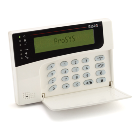
Page 37: Using The Lcd Keypad
Using the LCD Keypad Figure 20: The LCD Keypad Face The LCD keypad is a visual interface tool that helps you operate the ProSYS Main Panel. The LCD keypad contains six LED indicators and a variety of keys. Their typical uses are described in the following table: NOTE: For information regarding the TouchScreen keypad please refer to the instructions supplied with the... -
Page 38: P Rogramming From The Lcd K Eypad
Item Key/LED Programming Mode/Function A, B, C, and D Use these keys for defining groups and macros. Refer to the Groups section in Chapter 1, Introducing ProSYS for further details. Use this key to exit the current programming selection and move up to the next higher level in the programming hierarchy. - Page 39 Accessories: Auto Settings section of Chapter 5, Using the Installer Programming Menus for further details). To access the Installer Programming Menu for the first time (or after the Main Panel has been defaulted): 1 When you power up the system, the following display appears: PLEASE WAIT…...
- Page 40 2 Press [7] to select the Installer option or use the key. The keypad displays the first option, as follows: 3 Press [1] Advanced. The keypad prompts you for the Installer code, as follows: 4 Enter the default Installer Code, depending on the ProSYS model: O ProSYS 128: [0][1][2][8] O ProSYS 40: [0][1][4][0] O ProSYS 16: [0][1][1][6]...
- Page 41 Restoring Manufacturer's Programming Defaults You may find it useful to be able to remove all changes made to the Main Panel's programming and restore the default settings provided by the manufacturer. Restoring defaults requires performing both of the procedures below. The first procedure enables the restoring option and the second procedure is the actual restoring process.
- Page 42 If a tamper occurs in the system (Bell, box or other) the display will show a list of the tamper faults in the system. It is advisable to scroll down the list and fix the tamper before exiting the installer programming mode to prevent tamper alarm.
-
Page 43: Keypad Timeout
Keypad Timeout If, after 15 minutes, no entry is made to a keypad that has been placed in the Installer Programming mode, it will produce an audible reminder, consisting of several beeps in rapid succession, along with the following display: Pressing any key stops the beeping. - Page 44 2 Remove the J2 jumper plug from its position on one pin of the J2 connector. 3 Position the J2 jumper plug on both of the two pins of the J2 connector. 4 Momentarily remove all power from the Main Panel (both AC and Standby Battery). 5 Restore all power to the Main Panel.
-
Page 45: Chapter 5 Using The Installer Programming Menus
Chapter 5 Using the Installer Programming Menus This chapter describes the ProSYS programming options and functions, as well as all quick key shortcuts. They are presented in a table of menus and are listed according to their number, as follows: System, page 46 Zones, page 62 Utility Output, page 93... - Page 46 2 Press the Quick Keys listed in sequence (from left to right) to locate the option listed in the Parameter column and then press NOTE: When programming items in sequence, you can use the key to exit to the previous level and the key to toggle the options.
- Page 47 3 Access and configure the parameters in the Time Define menu, as follows: System: Time Define Quick Keys Parameter Default Range Exit/Entry Delay 1 Exit/Entry Delays (Group 1). Entry Delay 1 30 seconds 0-255 seconds Duration of Group 1 Entry Delay. Note: For SIA CP 01 installations the range of entry time should be between 30 to 240 seconds with default of 30 seconds.
- Page 48 System: Time Define Quick Keys Parameter Default Range Wireless Module Times Specifies the time intervals relating to the operation of the wireless module. Jamming Time NONE NONE, 10, 20 or 30 seconds Specifies the period of time that the ProSYS's wireless module tolerates unwanted radio frequencies capable of blocking (jamming) signals produced by the system's transmitters.
- Page 49 System: Time Define Quick Keys Parameter Default Range In the case of a cut phone line, this parameter specifies the delay period before reporting the event into the event log or operating the Utility Output. 00 indicates no supervision of the telephone line Guard Delay MIN: 30 01-99 minutes...
-
Page 50: Fire Alarms
Quick Keys Parameter Default Range Bell Squawk YES/NO YES: If a keyswitch or a rolling code remote control is used, a brief "chirp" is produced from the system's external sounder(s) (at the conclusion of the Exit Delay period), as follows: ♦... - Page 51 Buzzer-->Bell YES/NO YES: If an alarm occurs when the system is armed in the STAY mode, each keypad sounds for 15 seconds before the external sounders operate. NO: An alarm in the STAY mode causes each keypad and any internal sounders to operate simultaneously.
- Page 52 Abort Alarm YES/NO YES: If an alarm is sent in error, it is possible for the MS to receive an Abort Alarm Code, sent subsequent to the initial Alarm Code. This happens if a valid User Code is entered to reset the alarm within 90 seconds of initiation. NO: No Abort Alarm Code can be sent once an alarm has been triggered.
- Page 53 Arm Pre-Warning YES/NO Related to auto arm/disarm operation. YES: For any partition(s) set up for Auto Arming, an audible Exit Delay (warning) countdown will commence 4.25 minutes prior to the automatic arming. (Refer to the user's Daily Arm function in the ProSYS User's Manual for additional details.) During this period, Exit Delay beeps will be heard in the keypads assigned to these partitions.
- Page 54 IMQ Install YES/NO YES: Causes the following parameters to function as follows: Auto Arm Bypass: If there is an open zone during the Auto Arm process, the system will be armed, and an alarm will be sounded (unless the open zone is closed). Guard User: If a Guard user disarms a partition, the system will be armed automatically after the predefined time period (refer to Guard, page 49).
- Page 55 Disarm Stop FM YES/NO YES: The Follow-Me calls will stop when the partitions are disarmed by a User Code or proximity card. NOTES: When a latched keyswitch is activated, you can only disarm the system by releasing the latched keyswitch. When the Advanced Digital Voice module is connected to the system, the Disarm Stop FM feature acts as NO even if it is defined as YES.
- Page 56 Prox AM=Tamper YES/NO Used to determine the operation of the proximity anti masking detection indicated by the MW channel in the WatchOUT DT detector. YES: Proximity anti mask detection will activate the tamper alarm. NO: Proximity anti mask detection will be regarded as a trouble event. Note that Proximity AM operates for approximately 2.2 seconds when the detector is approached in close proximity.
- Page 57 System: Set Clock The Set Clock menu enables you to set the system's date and time. To access the Set Clock menu: 1 Access the System menu, as described on page 46. 2 From the System menu, press [3] to access the Set Clock menu options. The following display appears: 3 Access and configure the parameters in the Set Clock menu, as follows: System: Set Clock...
- Page 58 System: Windowing Quick Keys Parameter Default Range Sets the days of the week in which the window is activated. Use the keys to select the days of the week. key to toggle between Y and N to define if the window Use the is active for the given day.
- Page 59 To enter a completed label into the system, press Enter. The number of allowed characters for each type of label varies, as follows: ♦ Zone Label: Up to 15 characters ♦ Partition Label: Up to 12 characters ♦ Programmable Output Label: Up to 12 characters ♦...
- Page 60 System: Tamper Sound The Tamper Sound menu contains parameters that enable you to set the sound(s) that will be produced by the ProSYS after a Tamper violation of a keypad and/or an expansion module. To access the Tamper Sound menu: 1 Access the System menu, as described on page 46.
- Page 61 keeping all Parameters, Labels, and User/Installer Codes intact. As with any instance of a total loss of power, you must reset the system's TIME and DATE. System: Service Information The Service Information menu supplies servicing information accessible to the system's users.
-
Page 62: Zone
Zones The Zones menu provides access to submenus and their related parameters that are used for programming the characteristics of each of the system's protected zones. You can program by zone or by category. The first submenu allows you to program all parameters for each zone one by one. - Page 63 The following procedure describes how to program the full complement of parameters for each zone on a one-by-one basis. To access the One by One menu: 1 Access the Zones menu, as described on page 62. 2 From the Zones menu, press [1] to access the One by One menu options. The following display appears: NOTES: In the mm:zz designation, the mm = the module ID number, and the zz = the zone number for this...
- Page 64 IMPORTANT: When using the One by One method, the listing of each zone's parameters is sequential. Once Zone 1's parameters have been programmed, they are followed by Zone 2's, then Zone 3's, and so forth. To program one or more of the system's zones using the One by One method, changes made to any (or all) of the Zone parameters will NOT be recorded without going through the One by One list, ending with the Zone Labels parameter of the last zone you want to program.
- Page 65 6 Use the keys to select the group and use the key to toggle between [Y] YES and [N] NO. NOTE: Each partition has 4 groups. The zone group definition is common to each of the partitions assigned to the zone. Zones: Zone Type The Zone Type menu contains parameters that enable you to program the zone type for any zone.
- Page 66 Zones: Zone Type Quick Keys Parameter Default Arming Level/Range Exit (OP)/Entry Default for zone 1 ARM/STAY Used for an exit/entry door, open during the armed period. This zone behaves as described in the Exit/Entry 1 parameter, shown above, except that, if faulted when the system is being armed, it does NOT prevent arming.
- Page 67 Zones: Zone Type Quick Keys Parameter Default Arming Level/Range I+Exit(OP)/Entry (Interior+Exit(OP)/Entry) Used for an exit/entry door that, for convenience, may be kept open when the system is being armed, as follows: In AWAY (ARMED) mode, refer to the explanation in Zone Type 03, page 66.
- Page 68 Zones: Zone Type Quick Keys Parameter Default Arming Level/Range 24 Hours Usually assigned to protect non-movable glass, fixed skylights, and cabinets (possibly) for shock detection systems. A violation of such a zone causes an instant intrusion alarm, regardless of the system's state.
- Page 69 Zones: Zone Type Quick Keys Parameter Default Arming Level/Range This type of zone is used to avoid a false alarm by acting like an Exit (OP)/Entry zone (see Exit (OP)/Entry, page 66). When triggered (after arming the system and closing the door or opening the door, arming the system, and closing the door), the system's Exit Delay time period will be shortened to 3 seconds.
- Page 70 Zones: Zone Sound The Zone Sound menu contains parameters that enable you to program the sound produced when a system zone triggers an alarm. Reports to the MS are not affected by any of the options in this menu. To access the Zone Sound menu: 1 Access the Zones menu, as described on page 62.
- Page 71 Zones: Zone Sound Quick Keys Parameter Default (BELL/A BUZZER/D) NOTE: The following feature is active only when a zone alarm event is triggered. Non 24H zone: Alarm event from the zone is generated only when the associated partition is armed – In this case when the zone sound is defined as "BELL/A, BUZZER/D"...
- Page 72 Uses normally-closed (NC) and/or normally-open (NO) contacts in a zone terminated by a supplied 4.7 KΩ End-of-Line Resistor (provided). DEOL Uses normally-closed (NC) contacts in a zone using 4.7 KΩ +6.8 KΩ End- of-Line Resistors to distinguish between alarms and tamper conditions. See Figure 2-4: Zone Connection Diagram in Chapter 2, Mounting and Wiring the Main Panel.
- Page 73 Use this option to define TEOL termination (see above description) for the relay zone input that exists on a BUS zone detector. Zones: Loop Response The Loop Response menu enables you to set the different times for which a zone violation must exist before the zone will trigger an alarm condition.
- Page 74 Zones: Loop Response Quick Keys Parameter Notes: 1. Loop response times 0.5 hour to 4 hours can be assigned only to zones 1 to 8 on the Main Panel or to zones located on the fast zone expander RP128EZ8F00A 2. The programming option of loop response 0.5 hour to 4 hours will be between 4-11 for zones located on the main menu while on the fast zone expander RP128EZ8F00A the programming location is between 5-12 Zones: Cross Zones...
- Page 75 Zones: Cross Zone Quick Keys Parameter Default Zone Crossing The Zone Crossing menu is used for additional protection from false alarms and contains parameters that enable you to link together two related zones. Both must be violated within a designated time period (between 1 and 9 minutes) before an alarm occurs.
- Page 76 2 Press to label Zone 01 (or enter another zone number). The following display appears: 3 Refer to Entering a New Label Using the LCD Keypad, page 58, for details about how to enter a label. Zones: Maintenance The Maintenance menu provides some useful tools for system maintenance. To access the Maintenance menu: 1 Access the Zones menu, as described on page 62.
- Page 77 Zones: Maintenance Quick Keys Parameter Delete a Zone Deactivates a designated zone by setting its Zone Type to , while maintaining all the previously programmed parameters. 1. Press [2]. keys or the [1 to 9] keys to 2. Use the select the zone that is to be deleted.
- Page 78 Zones: Maintenance Quick Keys Parameter Wireless Module Calibration Measures the RF noise that the receiver is picking up. This is used for jamming indication in order to eliminate false jamming alarms. The range is 00-99. 1. Press [5]. The following display appears: 2.
- Page 79 Zones: Maintenance Quick Keys Parameter Wireless Zone Allocation Options 1. Select the zone number intended for the first wireless transmitter. The first eight zones are reserved for the hardwired zones on the Main Panel. The following display appears: 2. Press the required option, as follows: O Press [1] to skip to the next transmitter assignment, O -OR- O Press [2] to overwrite the data into the selected location and...
- Page 80 Zones: Maintenance Quick Keys Parameter 4. Use the keys to select the zone number for the next wireless transmitter. 5. Press the key to return to the higher programming level. Zone Self-Test This feature provides an automated self-test for a selected group of localized intrusion sensors (for example, glass break detectors, sound discriminators and shock sensors) which respond to an artificial source of noise and/or vibration.
- Page 81 Zones: Maintenance Quick Keys Parameter CHOOSING ZONES FOR SELF-TESTING: 1. Press [8]. The following display appears: 2. Press to specify the first of 16 possible zones for self- testing. The following display appears: 3. Enter the zone number of the first selected zone. 4.
- Page 82 Zones: Maintenance Quick Keys Parameter 5. Use the keys to reposition the cursor. 6. Press 7. Press the key once. The following display appears: 8. Press . The following display appears: 9. Insert the time interval, in hours, between tests. The default is 00 hours.
- Page 83 Zones: Maintenance Quick Keys Parameter 7. Press [8] to select the sensors test. The following display appears: 8. Press 9. Select the manner in which the UO is to operate, by choosing [2] PULSE N/O. The following display appears: 10. The UO, acting like a normally-open switch, is closed for a predetermined period, completing a circuit that activates a noise source.
- Page 84 Zones: Maintenance Quick Keys Parameter 4. Press 5. To add a second zone for Soak Test, press and repeat the procedure above, -OR- Press the key to return to the previous menu. Zones: Miscellaneous The Miscellaneous menu enables you to enable or disable the forced arming option, to define number of pulses for a zone and define the parameters of BUS zones.
- Page 85 Zones: Miscellaneous Quick Keys Parameter Default Range 1. Press [1] and then press . The following display appears: 2. Enter the number of the zone for forced arming and press keys to select ENABLE or 3. Use the DISABLE and press .
- Page 86 Zones: Miscellaneous Quick Keys Parameter Default Range BUS Zone Parameters The BUS Zone Parameters menu contains parameters that enable you to program the special parameters of a BUS zone. The options are determined according to the BUS detector type: ♦ Lunar Grade 3: A dual technology ceiling detector with a mounting height of up to 8.6m (28ft) that incorporates Anti-Cloak Technology (ACT).
- Page 87 Zones Miscellaneous: BUS Zone – iWISE DT Grade 2 Quick Keys Parameter Default Range MW (Microwave) Range Trimmer Defines the microwave channel range. [1] Minimum [2] 25% [3] 50% [4] 65% [5] 85% [6] Maximum [7] Trimmer (MW is defined by the trimmer setting on the PCB) Defines the Anti-Cloak™...
- Page 88 Zones Miscellaneous: BUS Zone – Lunar Grade 3/iWISE DT Grade 3 Quick Keys Parameter Default Range Defines the Anti-Cloak™ Technology (ACT) operation mode. [1] No - Disables the ACT mode. [2] Yes - Enables the ACT mode. Automatic Microwave Bypass Defines whether the MW channel will be bypassed or not while the detector identifies trouble in the MW channel.
- Page 89 Zones Miscellaneous: BUS Zone – iWISE QUAD Grade 2 Quick Keys Parameter Default Range LEDS Defines the LEDS operation mode. [1] Off - Disables the LEDS operation. [2] On – Enables the LEDS operation. Sensitivity High Defines the sensitivity of the detector (PIR). [1] Low [2] High Self Test Remote...
- Page 90 Zones Miscellaneous: BUS Zone – Lunar Grade 3/iWISE DT Grade 3 Quick Keys Parameter Default Range Self Test Remote Used to test detection technologies. In the event of a failed test, a Self Test Trouble is created. [1] Remote (manual) - Performed by the system when a user manually selects the Diagnostics option from the Maintenance menu via the ProSYS User Functions menu.
- Page 91 Zones Miscellaneous: BUS Zone – WatchOUT DT Quick Keys Parameter Default Range LEDS 3 LEDS Defines the LEDS operation mode. [1] Off - Disables the LEDS operation. [2] Red Only - Only the Red LED will operate. This option is highly recommended to avoid the possibility that a burglar will “Learn”...
- Page 92 Zones Miscellaneous: BUS Zone – WatchIN DT Grade 3 Quick Keys Parameter Default Range LEDS 3 LEDS Defines the LEDS operation mode. [1] Off - Disables the LEDS operation. [2] Red Only - Only the Red LED will operate. This option is highly recommended to avoid the possibility that a burglar will “Learn”...
-
Page 93: U Tility O Utput
Utility Output The Utility Output menu provides access to submenus and their related programming parameters that enable you to choose the event that will trigger a selected Utility Output, as well as the manner in which the output will be applied. Adding one or more Utility Output expansion modules to the system makes an extensive list of switched output possibilities available. -
Page 94: Communication Failure
1 Press to disable the selected utility output. Utility Output: System The System menu contains Utility Output parameters that follow the System Event. To access the System menu: Access the Utility Output menu, as described on page 93. 1 From the Utility Output menu, press [1] to access the System menu options. The following display appears: 2 Press . - Page 95 Utility Output: System Quick Keys Parameter Ground Pulse Activates when the ProSYS dialer dials out. This option is rarely used and is intended for older phone systems that require a "Ground Start" (a momentary connection between one side of the phone line and "earth") to obtain a dial tone.
- Page 96 Utility Output: System Quick Keys Parameter Digital Key Reader Communication This Utility Output is activated when there is a BUS communication problem with the Proximity Key Reader. The pattern of the operation is Pulsed, and the default is 01 second for the pulse duration. The Utility Output will be activated for 5 consecutive times between the time that the Main Panel identifies a communication problem with the Digital Key Reader and the time it sends a restore event.
- Page 97 3 Select the partition event to be followed from those listed below, using the keys to move the cursor left or right, respectively. Utility Output: Partition Quick Keys Parameter Ready Follow Activates the Utility Output when all the selected partition(s) are in the READY state.
-
Page 98: Zone Bypass
Utility Output: Partition Quick Keys Parameter Exit/Entry Follow Activates the Utility Output when the selected partition(s) initiates an Exit/Entry Delay period. Fire Trouble Follow Activates the Utility Output when a FIRE TROUBLE is detected in the selected partition(s). Day (Zone) Trouble Activates the Utility Output when a DAY ZONE TROUBLE is detected in the selected partition(s). - Page 99 Utility Output: Partition Quick Keys Parameter Zone Loss Alarm An alarm is activated when a wireless zone is lost. 4 Press . The following display appears: NOTE: The XX in the UO=XX refers to the number of the Utility Output currently being programmed. 5 Use the key to toggle between [Y] YES and [N] NO to designate the partition(s) that will activate the selected Utility Output (UO),...
- Page 100 Utility Output: Zone Quick Keys Parameter Activates the Utility Output when the selected zone is armed by the system. Disarm Follow Activates the Utility Output when the selected zones are disarmed. 4 Press . The following display appears: 5 Enter the zone numbers in the group and press after each one.
- Page 101 Utility Output: Pattern of Operation Quick Keys Parameter Default Range Pulse N/C 05 seconds 01-90 seconds The Utility Output is always Activated (N/C) before it is triggered (pulled down to negative). When triggered, it deactivates for the Pulse Duration specified below and then reactivates automatically.
- Page 102 Utility Output: Pattern of Operation Quick Keys Parameter Default Range NOTE: You can create and/or edit a 10-character label description for each Utility Output. Refer to Entering a New Label Using the LCD Keypad, page 58, for additional details. Activation/Deactivation When the Utility Output is following more than one Partition or Zone, the Installer can choose the logic of the Utility Output activation or deactivation, as follows: If the Pattern of Operation is defined as Latch N/O or Latch N/C, the Installer can choose the...
-
Page 103: C Ode M Aintenance
Code Maintenance The Code Maintenance menu provides access to submenus and their related parameters that enable you to maintain the User Codes in the system. In addition, the ProSYS contains the following special codes: Grand Master Code: Used by the system's owner or chief user. Installer Code: Used by the ProSYS installation company technician to program the Main Panel. - Page 104 Code Maintenance: Authority Default: User The Authority menu enables you assign the Authority Level of each User Code. There are seven Authority Levels to match the needs of various users, as described in Authority Levels, below. To access the Authority menu: 1 Access the Code Maintenance menu, as described on page 103.
- Page 105 O Resetting the Switched Auxiliary Output O Activating designated Utility Outputs O Changing his/her own User Code O Controlling uploading/downloading activities O Administering selected system tests, except Walk Testing Arm Only: There are no restrictions in the number of Arm Only Codes (as long as they don't exceed the number of codes remaining in the system).
- Page 106 ProSYS 128: [0][1][2][8] ProSYS 40: [0][1][4][0] ProSYS 16: [0][1][1][6] RISCO Group recommends changing the factory default to a new code unique to the Main Panel and/or to the MS personnel, as described in the procedure below. To access the Installer menu: 1 Access the Code Maintenance menu, as described on page 103.
- Page 107 3 Enter the new code, using the keypad's [0 to 9] keys. 4 Use the keys to overwrite the default and press 5 Confirm your selection by re-entering the same code and pressing 6 Press the key to return to the previous level. Code Maintenance: Sub-Installer Default: 0228 The Sub-Installer Code allows limited access to selected parameters from the Installer...
- Page 108 3 Use the key to toggle between [Y] YES and [N] NO to determine whether you want to save any programmed data and press 4 From the normal (user's) display, enter the SELECTED mode by pressing [2]. 5 Enter the Sub-Installer's Code and press .
- Page 109 Code Maintenance: Code Length Quick Keys Parameter Displays the 6-digit codes. 1. Use the keys to display the 6-digit codes. 2. Press . When you make a change in the Code Length, the following display appears: 3. Use the key to change the default 4.
-
Page 110: Dialer
Dialer The Dialer menu provides access to submenus and their related parameters that enable ProSYS to establish communication with the MS and transmit data. After you access the Dialer menu from the main Installer Programming menu, as described in this section, you can access the following submenus: Link-Up, page 110 Customer Account Numbers, page 113 Communication Format, page 114... - Page 111 3 Access and configure the parameters in the Link-Up menu, as follows: Dialer: Link Up Quick Keys Parameter Range MS Link-Up The ProSYS enables to report events to the MS receiver in four connectivity (link-ups) options, depending on the communication options at the MS site: Voice channel (land line or GSM): Up to 32 alphanumeric characters 1.
- Page 112 32 digits of the MS phone number with prefix included. NOTE: RISCO Group’s IP/GSM receiver has to be used at the MS side. GPRS The ProSYS will report the MS via the GPRS network using the GSM/GPRS module.
- Page 113 Dialer: Link Up Quick Keys Parameter Range U/D Phone 1 Up to 32 alphanumeric characters Type in up to 32 digits followed by . Include dialing prefixes and area code or special letters. U/D Phone 2 Up to 32 alphanumeric characters The second number for the U/D software Special Letters When entering special letters, you must press and hold the...
- Page 114 3 Use the keys to select a partition and press . If you select partition 1 or 2 in the ProSYS 40 or ProSYS 128,the following display appears: 4 Select the MS telephone number (up to three available numbers) and press .
- Page 115 4 Use the [0 to 9] keys to assign the format code (for example, 0420 ADEMCO Contact ID format. 5 Press 6 Press again followed by the key to return to the previous level. NOTE: For SIA and Contact ID formats, refer to Dialer: Auto Codes, page 132. 7 Access and configure the parameters in the Communication Format menu, as follows: Dialer: Communication Format Quick Keys...
- Page 116 Protocols Communication Formats Format Code Sescoa/Franklin/Vertex/DCI Fast 0116 Sescoa/Franklin/Vertex/DCI-Extended 0156 Universal High Speed Non-Extended 0112 Radionics Protocols: Radionics, 20 PPS handshake at 1400 Hz 0202 handshake at 2300 Hz 0212 Radionics, 20 PPS-Extended handshake at 1400 Hz 0242 handshake at 2300 Hz 0252 Radionics, 40 PPS handshake at 1400 Hz...
-
Page 117: Access Code
Default Access Code 5678 Enables you to define an Access Code that is stored in the ProSYS. RISCO Group recommends using a different 4-digit Access Code for each installation. In order to enable communication between the and the installation, the same Access Code must subsequently be entered into the corresponding account profile created for the installation in the Upload/Download software. - Page 118 3. Press MS Lock 000000 MS Lock is a security function used in conjunction with RISCO Group's Upload/Download software. It provides greater proprietary security when viewing MS parameters. The same 6-digit code, which will be stored in the panel, must be entered into the corresponding account profile created for the installation in the Upload/Download software.
- Page 119 3 Access and configure the parameters in the Controls menu, shown in the table below, as follows: O Access each parameter by pressing the menu number keys or by using the keys. O Press the key to toggle between [Y] YES and [N] NO and press (repeat for each parameter, as required).
- Page 120 Dialer: Controls Quick Keys Parameter Default User Initiated Call YES: For a remote Upload/Download session to take place, the user must first enter specific keypad commands in the User Functions mode. Refer to the ProSYS User's Manual (Quick Keys [*][2][8]) for additional details. NO: Upload/Download operations are possible without requiring the user's participation.
- Page 121 Dialer: Controls Quick Keys Parameter Default UL Installation YES: Disables features inappropriate for UL listed installations. This feature disables the use of Upload/Download and permits a status display only when remotely accessed. NO: No features are disabled. Show Kissoff YES: All five LEDs on the right side of the keypad(s) light for one second when the dialer receives the kissoff signal from the MS’s receiver.
- Page 122 2 From the Dialer menu, press [6] to access the Parameters menu options. The following display appears: 3 Access and configure the parameters in the Parameters menu, shown in the table below, as follows: O Access each parameter by pressing the menu number keys or by using the keys.
- Page 123 Dialer: Parameters Quick Keys Parameter Default Range Wait 5 Seconds Select [1] and press Wait 60 Seconds Select [2] and press Dialing Method DTMF DTMF (Touch Tone ®), Pulse @ 20 BPS, and Pulse @ 10 BPS When selecting the dialing method, your choice must be compatible with the type of phone service available at the protected premises.
- Page 124 Dialer: Parameters Quick Keys Parameter Default Range VM Retries 01 to 05 Defines the number of times a voice message repeats itself once received by a Follow-Me. Dialer: Report Split The Report Split menu contains parameters that enable the routing of specified events to up to three MS Receivers.
- Page 125 Dialer: Report Split Quick Keys Parameter Default 1st Backup 2nd Reports Openings and Closings to the 1st MS Link-Up. If communication is not established, calls the 2nd MS Link-Up. 1st Backup 2nd3rd Reports the 1st MS Link Up. If communication is not established calls the 2nd MS link up.
- Page 126 Dialer: Report Split Quick Keys Parameter Default section in the ProSYS User's Manual). In the below Follow Me quick keys, represents a selected Follow Me number between 1 and 16. Follow-Me numbers 1 through 9 can be accessed using quick keys or the Follow-Me menu, but 10 through 16 can only be accessed from the Follow Me menu.
- Page 127 Dialer: Report Split Quick Keys Parameter Default ACM Mail Events are reported to the Follow Me destination by E-mail using the ACM module. NOTE: Only Follow Me numbers 1 and 2 can be defined as ACM Mail. Follow-Me Partition Specify the partitions that will initiate the Follow-Me report due to a certain event that occurred in the assigned partitions.
- Page 128 Dialer: Report Split Quick Keys Parameter Default [16] Low Battery N (From main panel or power supply expander) [17] Wireless Jamming [18] BUS Trouble [19] Provider N (An automatic SMS SIM Credit message Message received from the provider phone can be (SMS/Email) transferred to a follow me number) [20]...
-
Page 129: Event Log
Dialer: Report Split Quick Keys Parameter Default [10] Phone Trouble Restore [11] GSM Low Battery Restore [12] GSM Trouble N (Restore of all GSM module faults) [13] Siren Low Battery Restore 2. After you have defined all the required phone events, press E-mail To enable event reporting using the ACM, the following parameters should be defined:... - Page 130 Dialer: Alarm Restore The Alarm Restore menu specifies under what conditions an Alarm Restoral is reported. This option informs the MS of a change in the specified condition(s) during an alarm restore. These reports need a valid Report Code. Refer to Report Codes, page 134, for additional details.
- Page 131 Dialer: Periodic Test The Periodic Test menu enables you to set the time period that the ProSYS will automatically call the MS or Upload/Download phone numbers in order to check the phone line connection. It also sends reports of non-urgent events, which reduces the number of calls made (only if the Call Save option is defined as YES).
- Page 132 Dialer: Periodic Test Quick Keys Parameter Default Range UD Test HR:00 00-24 hours MIN:00 00-59 minutes Used to schedule periodic Auto Batch download using the Upload/Download software. This is the day, time of day (in 24-hour format) and time interval at which the customer's ProSYS automatically calls the MS ’s computer to download the Batch (selected parameters).
- Page 133 Dialer: More Quick Keys Parameter Auto Codes The Auto Codes menu enables the resetting of all MS Report Codes to 00 without the need to restore factory defaults for the auto setting of the following MS formats: ADEMCO Contact ID Contact ID The ProSYS allocates Report Codes supporting ADEMCO Contact (Point) ID.
- Page 134 Dialer: More Quick Keys Parameter Delete All The ProSYS resets to 00 all previously programmed MS Report Codes. This does not change any other programmed parameters. 1. Press to select this option. The following display appears: 3. Press to confirm your choice. 4.
- Page 135 [1] Disabled [2] Enabled IP MS Polling This parameter checks connectivity between RISCO Group's IP/GSM Receiver software and the ProSYS panel by sending polling signals from the ProSYS ACM via the IP channel. Ensure that the IP channel has been configured properly in the IP/GSM Receiver software.
- Page 136 Dialer: More Quick Keys Parameter defined according to the MS report split for “urgent events”. The time intervals for performing the polling with each MS are defined in the below described IP Primary, Secondary and Backup parameters. The following table describes how the three MSs use the primary, secondary and backup time intervals in the various MS report split options.
-
Page 137: Report Code
Dialer: More Quick Keys Parameter IP MS Secondary 00360 (x10 sec) 0-65535 sec Defines the polling interval through the secondary channel. When using the default time, a polling message is sent every 3600 seconds (1 hour). When the IP Secondary polling time is defined as 0, no polling message is sent to the MS (when the MS channel is in the Secondary polling mode). - Page 138 Disarm Codes, page 147 Miscellaneous, page 148 Special Communication, page 150 Accessory Code, page 150 To access the Report Codes menu: From the main Installer Programming menu, press [6], or press the keys until you find the number [6] Report Codes option and then press .
- Page 139 Report Codes: Emergency Key The Emergency Key menu enables you to define the codes transmitted to the MS when an alarm is sent (meaning Police, Fire, and Auxiliary Emergency) via a keypad's emergency keys. To access the Emergency Key menu: 1 Access the Report Codes menu, as described on page 137.
- Page 140 Report Codes: Zones The Zones menu contains parameters of the Report Code generated when an alarm (or alarm restoral) occurs due to the violation of an armed zone. To access the Zones menu: 1. Access the Report Codes menu, as described on page 137. 2.
- Page 141 Report Codes: Zones Quick Keys Parameter Default Low Battery To report a low battery condition in a wireless transmitter. Low Battery Restore To report the correction of a low battery condition. Report Codes: Accessory Tamper The Accessory Tamper menu contains codes that enable reporting the violation (or restoral) of the tamper switch on a system accessory (a keypad or expansion module).
- Page 142 Power Supply Module [1] Power Supply Tamper: Tamper Codes for power supply modules. [2] Power Supply Tamper Restore: Tamper Restore to Normal Report Code for power supply modules. Event Logger [1] Event Logger Tamper: Tamper Codes for event logging modules. [2] Event Logger Tamper Restore: Tamper Restore to Normal Report Code for event logging modules.
- Page 143 O Enter the appropriate Trouble Condition or Trouble Restore number. O Enter the 2-digit code representing the event. O Press O Press the key to return to the previous programming level. Report Codes: Main Trouble Quick Keys Parameter Default Trouble Conditions Trouble Codes assigned to the Power Supply Accessory module: [1] Low Battery: reports the detection of a weak (or missing) standby battery.
- Page 144 Report Codes: Main Trouble Quick Keys Parameter Default Trouble Restorals Trouble restoral codes assigned to the ProSYS Main Panel: [1] Low Battery: reports the restoring to normal of a weak (or missing) standby battery. [2] Bell: reports the restoring to normal of an internal sounder wired to the Main Panel.
- Page 145 Report Codes: Power Supply Accessory Module Trouble Default: 00 The Power Supply Accessory Module Trouble menu contains codes that enable reporting the detection or restoral of troubles relating to the operation of the Power Supply Accessory module. To access the Power Supply Accessory Module Trouble menu: 1 Access the Report Codes menu, as described on page 137.
- Page 146 Report Codes: Power Supply Accessory Module Trouble Quick Keys Parameter Default [3] AC Restoral: reports the restoring to normal of the AC power supply to the Power Supply Accessory module. [4] AUX: reports the restoring to normal of the Auxiliary power supplied by the Power Supply Accessory module.
- Page 147 Report Codes: Arm Codes Quick Keys Parameter Default NOTE: No specific user identification is possible. Refer to the ProSYS User's Manual for additional details. Remote Armed A Report Code used when the system is Remotely Armed as a result of actions performed by the MS using its Upload/Download software.
- Page 148 Report Codes: Disarm Codes Quick Keys Parameter Default Keyswitch Disarmed Code to report system disarm via a keyswitch. NOTE: No specific user identification is possible. Auto Disarmed Report Code used when the system is Auto Disarmed by a previously scheduled event. NOTE: No specific user identification is possible.
- Page 149 Report Codes: Miscellaneous Quick Keys Parameter Default Exit Programming Report Code for termination of the Installer Programming mode, either locally (via the LCD keypad) or remotely (via the Upload/Download software). Periodic MS Test Report Code used for periodic MS Test transmissions. (Refer to Dialer: Periodic Test, page 131, for additional details).
- Page 150 Report Codes: Miscellaneous Quick Keys Parameter Default To open the voice alarm confirmation channel, an extra event report (following the report of an urgent alarm) is sent to the MS receiver. This event informs the receiver that the ProSYS will automatically switch to Listen-In mode at the end of event transmission.
- Page 151 3 Access and configure the parameters in the Accessory Code menu, as follows: Report Codes: Accessory Code Quick Keys Parameter Default Wireless Zone Expander Press [1] to access each sub-category, as shown below. Jamming Trouble 1. Enter the Wireless Zone Expander's 1-digit physical ID. 2.
- Page 152 Report Codes: Accessory Code Quick Keys Parameter Default Printer Trouble Restore Enter the Printer module's 1-digit physical ID. 1. Enter the 2-digit Report Code for the restore to normal of the detection of printing difficulty (see above). 2. If this event is not to be transmitted, use the 00 default. 3.
- Page 153 Report Codes: Accessory Code Quick Keys Parameter Default Report codes for GSM faults: [1] Tamper: report code of GSM box tamper alarm condition. [2] Communication Trouble: report code of communication trouble between the GSM module and the ProSYS. [3] Mains Trouble: report Code of loss of main power to the GSM module. [4] Low Battery: report code for low battery condition.
-
Page 154: A Ccessories
Accessories The Accessories menu provides access to submenus and their related parameters that enable you to add to or remove keypads and expansion modules. From this section you can also access system tests to verify keypads and modules in order to check the quality of their connections to the 4-wire BUS, as described in the following sections: Add Delete Module, page 154... - Page 155 Accessories: Add Delete Module Quick Keys Parameter Default Range Keypad STEP 1: CHOOSING A KEYPAD TYPE: 1. Press [1]. The following display appears: 2. Use the keys to position the cursor over the keypad ID number for which you want to assign (or delete) a keypad. The first keypad must be assigned to the first ID number, which is 01.
- Page 156 Accessories: Add Delete Module Quick Keys Parameter Default Range NOTES: 1. Non-partitioned systems are regarded as Partition 1. This partition specifies the location of the keypad and is mainly used for quick arming. Pressing the Arm Key automatically arms the partition. 2.
- Page 157 Accessories: Add Delete Module Quick Keys Parameter Default Range FZ08 (an 8 Hardwired Zone Expander with FAST and extended loop response definitions) BZ08 ( Virtual 8 Zone Expander) BZ16 (Virtual 16 Zone Expander) G3Z08 (an 8 Hardwired Zone Expander with TEOL termination) G3Z16 (a 16 Hardwired Zone Expander with TEOL termination) BZE08 (8 BUS zone expander) BZE16 (16 BUS zone expander)
- Page 158 Accessories: Add Delete Module Quick Keys Parameter Default Range 3. Place the cursor over the TYPE field and use the key to toggle between the options and select the required Utility Output, as follows: NONE UO04 (a 4-Output Relay-Type Unit) UO08 (an 8-Output Solid-State Type Unit) XO08 (the X-10 Transmitting Module) UO02 (2-Output Relay Type located on the 3A switched power...
- Page 159 Accessories: Add Delete Module Quick Keys Parameter Default Range 3. Place the cursor over the TYPE field and use the key to toggle between the options and select the required Power Supply as follows: None PS01: 1.5A power supply PS02: 3A power supply 4.
- Page 160 Accessories: Add Delete Module Quick Keys Parameter Default Range NONE The event log stores events with their zone, UO number, and user number and time. Each ProSYS model has the built-in capacity to store 256 events, and the two larger models can be expanded, as follows: ProSYS 16 - Cannot be expanded.
- Page 161 Accessories: Add Delete Module Quick Keys Parameter Default Range 3. Place the cursor over the TYPE field, and press to choose either NONE or WBT8 (the only such module). 4. Press 5. Repeat the process for any other Wireless Button modules and Wireless Buttons.
-
Page 162: Access Control
Accessories: Add Delete Module Quick Keys Parameter Default Range NOTE: You can define two printers in the system, but both printers cannot print the same events. 1. Press to store your choice and to repeat the process if there is a second Printer module in the system. 2. - Page 163 Accessories: Add Delete Module Quick Keys Parameter Default Range step 6. -OR- Select 2 doors, 2 readers to initialize two doors, and then proceed to step 7. 6. If you selected 1 door, 2 readers in step 5, then toggle the keys to define the antipassback feature, as described below, and then press Select [Y] to enable the antipassback feature.
- Page 164 Accessories: Add Delete Module Quick Keys Parameter Default Range 3. Use the keys to position the cursor at ID=1 and type in the Proximity Key Reader ID number as defined by the dip switches that you set when you installed the module. 4.
- Page 165 Accessories: Add Delete Module Quick Keys Parameter Default Range status indication will be indicated on the reader 14. Press NOTE: Recording tags can be performed only from Proximity Key Reader ID number 1. Advanced Digital Voice Module 1. Press [2]. The following display appears: 2.
- Page 166 Accessories: Add Delete Module Quick Keys Parameter Default Range 4. Press . The Partition display appears. P=12345678 S=1 Y..5. Use the keys to select a partition key to toggle [Y] YES or [N] number and then use the NO to assign that partition to the siren. 6.
- Page 167 Accessories: Add Delete Module Quick Keys Parameter Default Range 2. Use the keys to position the cursor over ID=1 and type in the Bus Zone ID number that you are assigning or deleting. NOTE: Make sure that the detector's physical ID number is identical to the ID number you select during programming 3.
- Page 168 Accessories: Add Delete Module Quick Keys Parameter Default Range X.Modem The Fast PSTN Modem enables PSTN communication at 2400 Bps between a remote PC and the ProSYS security panel when programming the system using the Upload/Download software. 1. Press [7]. The following display appears: XModem MODULE: Type=XModm 2.
- Page 169 To access the BUS Test menu: 1 Access the Accessories menu, as described on page 154. 2 From the Accessories menu, press [3] to access the BUS Test menu options. The BUS testing begins to check the connections between the devices on the BUS, and the following display appears briefly: The system then displays the programmed device, its address, and the quality of the communication, expressed as a percentage, as shown in the following examples:...
- Page 170 The system displays each programmed device and its address. Walk Testing Comprehensive Walk Testing is an important part of system maintenance. It should be performed after installation and periodically afterwards by both the dealer and the customer. When conducted within the User Functions mode, Walk Testing permits any of the ProSYS keypads whose "Local Buzzers"...
-
Page 171: M Iscellaneous
Miscellaneous Default: NONE The Miscellaneous menu contains submenus that enable you to define the parameters of various accessories: Key-fob, below Siren, page 174 GSM, page 175 To access the Miscellaneous menu: From the main Installer Programming menu, press [8] or press the keys until you find the number [8] Miscellaneous option and then press . - Page 172 3 Use the keys to position the cursor and make any changes to the Button Number you want to learn-in to the system. 4 Press Changing the Wireless Button Parameters Each wireless button consists of 4 keys, and each key can be programmed to a different mode of operation.
- Page 173 8 Set the parameters for the UO Key #4 from the following options: O NONE: The key is disabled (default). O AWAY: The key is used for AWAY arming the assigned partitions. O STAY: The key is used for STAY arming the assigned partitions. O GROUP: The key is used for GROUP arming the assigned partitions O UO: The key is used to operate a Utility Output.
- Page 174 6 Press and then press to confirm your selection. Miscellaneous: Siren The Siren menu enables defining all parameters of an external siren that can be connected to the ProSYS as a BUS accessory. Up to 8 sirens can be added to the ProSYS and each can be assigned to any partition. Connection to the BUS enables Remote Control and Diagnostic support for a siren.
-
Page 175: Battery Load Test
Miscellaneous: GSM RISCO Group's GSM/GPRS BUS Module is a cellular communication module for use with RISCO Group security panels that can be used as a backup or a substitute to a normal PSTN line. Reporting to the MS can be performed using Voice, SMS or GPRS channel using RISCO Group's IP/GSM Receiver at the MS site. - Page 176 GSM Parameters Quick Keys Parameter Default PSTN Lost 10 seconds 010-255 seconds The time after which the module will switch over to the GSM network upon PSTN lost. (PSTN is connected to the GSM/GPRS module). This parameter is relevant only for GSM/GPRS full version module GSM Lost 10 minutes 001-255 minutes...
-
Page 177: Pin Code
GSM Parameters Quick Keys Parameter Default PBX Prefix A number dialed to access an outgoing line when the module is connected to a Private Branch Exchange (PBX) and not directly to a PSTN line. The ProSYS enables to program two PBX numbers. Each PBX number can contain up to 6 numeric characters. - Page 178 GSM Parameters Quick Keys Parameter Default GPRS The GPRS menu defines parameters ((Quick Key [8][2][1][5][1] to [8][2][1][5][3]) required when using the GPRS communication channel. Before programming these parameters, you should gather the required network settings information and enable the GPRS channel (for more information, contact the cellular provider).
- Page 179 Quick Keys Parameter Default This parameter checks connectivity between RISCO Group's IP/GSM Receiver software and the ProSYS panel by sending polling signals from the ProSYS GSM via the GPRS channel. Ensure that the GPRS channel has been configured properly in the IP/GSM Receiver software.
-
Page 180: Smtp Password
GSM Parameters Quick Keys Parameter Default When communication to MS#1 fails, polling occurs every 90 seconds according to the backup interval to MS#2. When communication returns to MS#1, polling reverts back to the secondary time interval and occurs every 3600 seconds (1 hour) to MS#2. GPRS Primary 00009 (x10 sec) 0-65535 sec... - Page 181 GSM Parameters Quick Keys Parameter Default SMTP E-mail prefix The GSM e-mail address prefix. Up to 16 characters can be used to define the e-mail prefix. For example, in the GSM@riscogroup.co.uk e-mail address, the prefix name is “GSM”). SMTP E-mail domain The GSM e-mail address domain name.
-
Page 182: A Ccess C Ontrol
Access Control Default: NONE The Access Control menu enables you to define all the parameters for the Access Control module. After you access the Access Control menu from the main Installer Programming menu, as described in this section, you can access the following submenus: Door Define, page 182 Card Code Position, page 185 Special Code, page 186... - Page 183 Access Control: Door Define Quick Keys Parameter Default Range Partitions Defines which partitions are assigned to the door. 1. Press [1] and then press 2. Use the keys to select a partition number and then use the key to toggle [Y] YES or [N] NO to assign that partition to the door.
- Page 184 Access Control: Door Define Quick Keys Parameter Default Range 4. Press Door Alarm Delay 10 seconds 1-99 seconds Determines the amount of time that the door can remain open before an alarm is activated (triggered on relay 3). This option also determines the amount of time that passes until an alarm is activated when the door is forced open.
- Page 185 If the card code position is changed for cards in Magnetic or Barcode technologies the cards previously defined in the system will not work and will need to be redefined in the system Refer to the card manufacturer or to your RISCO Group service provider for additional details regarding the card code format, if required.
- Page 186 3 Enter a number (between 00-37) to define the starting card code position. This position determines where the system will start reading the 8-digit code on the card. 4 Press Access Control: Special Code The Special Code menu enables you to assign codes to the arm cards defined in the system in order to perform operations in addition to opening the doors (such as arming the system).
-
Page 187: E Xit P Rogramming
Exit Programming The Exit Programming menu enables you to save any programming changes made during the current session. Important: Any changes you make to the programmed parameters are not saved until you exit the Installer Programming Menu correctly. To access the Exit Programming menu: 1 From the main Installer Programming menu, press [0] , or press the keys until you find the number [0] Exit Program option, shown below, and then press... - Page 188 O Discard your changes by using the key to change the [Y] YES to [N] NO on the display and then press . The following display appears: The keypad returns to the normal user display. ProSYS Installation and Programming Manual...
-
Page 189: Chapter 6 Installer Programming Within The User Functions Mode
Chapter 6 Installer Programming Within the User Functions Mode This chapter describes the ProSYS programming options and functions located in the user’s programming menu that can also be accessed and programmed by an authorized installer after inserting a valid installer code. The options and functions that can be programmed by an installer appear in the following sections under User Functions: Activities, page 62... - Page 190 2 Press . The keypad displays the first User Functions option, as follows: 3 Use the key to obtain the relevant menu item or use the specified Quick Key combination and your installer code. For example, to access Overload Restore, press: [2][0][2][Installer Code] Activities...
- Page 191 Activities Quick Keys Parameter Range received and the keypad functions as a GSM telephone. You can dial and listen to messages as with a regular telephone. To end the call press on the button Notes: 1. The outgoing call will always be executed trough the GSM channel. 2.
- Page 192 View Quick Keys Parameter Range Not Ready Status This parameter displays the partitions’ status, the troubles in the system and all the “not ready” zones. Scroll down using the key to view additional entries. Zone Status This parameter displays all system zones and their current status. Event Log This parameter enables viewing the event log of significant system events including date and time.
- Page 193 Maintenance Quick Keys Parameter Range Keypad Text This parameter momentarily tests the keypad indicators and the system's external sounder(s). Battery Test This parameter tests the system’s standby batteries. Diagnostics This menu enables performing diagnostic tests for: [1] BUS Zones [2] Power Supply [3] Siren [4] GSM More...
-
Page 194: Voice Message
Maintenance Quick Keys Parameter Range Accessories Versions This parameter enables viewing the current versions of ProSYS accessories: [1] BUS Zone versions [2] Power Supply version [3] Siren version [4] Proximity Key Reader version [5] GSM version Get ACM IP View the ACM IP address. Required for establishing remote communication for U/D through the IP network. - Page 195 After you access the Voice Message menu from the main User Programming menu you can access the following submenus: Play/Record, page 195 Test Message, page 199 To access the Voice Message menu: 1 From the main User Programming menu, press [9], or press the keys until you find the number [9] Maintenance option and then press .
- Page 196 You are now in the Play/Record menu and can access the required voice messages, as described in the following sections. Maintenance: Voice Message Quick Keys Parameter Range Common Message 1. Press [1]. The following display appears: COMMON MSG: 1)PLAY 2. Press the required option as follows: Press [1] to play the common message.
- Page 197 Maintenance: Voice Message Quick Keys Parameter Range Partition Message 1. Press [1]. The following display appears: CHOOSE PARTITION: 1) PARTITION 1 2. Select the partition number. 3. Press the required option as follows: Press [1] to play the partition message. Press [2] to record a new message.
- Page 198 Maintenance: Voice Message Quick Keys Parameter Range Utility Output Message Recording voice messages for Utility Outputs simplifies the process of remotely operating them by enabling the user to hear a meaningful name, such as Heating, for each Utility Output. This procedure involves: Selecting a Utility Output voice message.
- Page 199 Test Message Locally The Test Message locally option enables you to verify the operation of ProSYS’s voice playback capabilities. To perform a local test message: Access the Miscellaneous menu, as described on page 194. 1 From the Miscellaneous menu, press [3] to access Test Message and press The following display appears.
-
Page 200: Appendix A : Technical Data
Appendix A : Technical Data Main Panel 16.5 Volts AC @ 40 Volt-Amps (VA) (via integral transformer) Input Power 60 mA, typical / 70 mA, maximum Current Consumption 12 Volts up to 17 Amp-Hours (AH), typical Rechargeable Standby Battery Power Outputs: O Auxiliary Power 12 Volts DC @ 600 mA, maximum (from all AUX terminals) O Bell/LS (External) - Page 201 Zone Expansion Module: 16-Zone Current Consumption 27 mA, typical / 45 mA, maximum Main Panel Connection 4-wire BUS, up to 300 m from Main Panel Dimensions 16.5 cm x 6.6 cm x 1.8 cm BUS Zone Expansion Module Current Consumption 20 mA, typical Main Panel Connection 4-wire BUS, up to 300 m from Main Panel...
- Page 202 9.0 cm x 9.0 cm x 6.7 cm Dimensions 3A Switched Power Supply Expansion Module 16.5VAC @ 50VA (via 230VAC/16.5VAC/50Hz transformer). Input Power 12V Up To 21 Amp-Hours (AH) Rechargeable Standby Battery Auxiliary Output: 3A @13VDC Power Outputs: Bell/LS (External) Sounder Output: 1.7A @13VDC Bell/LS (External) Overload Protection: Automatic Electronic Protection 2 relays, 12VDC @ 3A max Dry Contact Relays...
- Page 203 Listen In/ Message Unit Input Power 8V DC to 14V DC Current Consumption 9 mA (standby) / 60 mA (active speaking - normal volume) / 130 mA (active speaking - full volume) Audio Signal Vin max = 2.5V pp / Vout max = 4V pp Dimensions 6.2 cm x 11.3 cm x 3.2 cm Voice Messages Module...
-
Page 204: Appendix B : Prosys Accessories
Appendix B : ProSYS Accessories Keypads Description ProSYS KL08 8-LED Keypad (LEDS and Keys text indication) ProSYS KL16 16-LED Keypad (LEDS and Keys text indication) ProSYS KCL LCD Keypad (LEDS and Keys text indication) ProSYS KCLP Proximity LCD Keypad+ 2 key tags (LEDS and Keys text indication) ProSYS KTAG Proximity key tags (x10) - Page 205 WL T51 Wristband panic transmitter WL T52 Wireless 2 panic button keyfob WL T6S Wireless Shock Detector White or Brown casing WL T6F Wireless flood Detector WL T6CO Wireless CO Detector WL T6G Wireless Glass Break Detector WL T6GS Wireless GAS Detector WL T312 Wireless WatchOUT WisDom KWL...
- Page 206 200VC Voice Module (3 messages) Message Box Unit Description ProSYS EVM Listen and speak-in module with message box ProSYS EVL Listen and speak-in module X-10 Module Description ProSYS EXT X-10 Transmitter Module Event Log Expander Description ProSYS EL5 Event log expander to 512 events ProSYS EL9 Event log expander to 999 events Advanced Communication...
- Page 207 iWISE 815DTBG2 iWISE DT AM Grade 2 , 15m (50 ft) iWISE 825DTBG2 iWISE DT AM Grade 2 , 25m (82 ft) iWISE 800QBG2 iWISE Quad 15m (50 ft) AM Grade 2 Demonstration Board Description ProSYS DBL ProSYS Laptop demo board Boxes Description ProSYS Metal box + tamper...
-
Page 208: Appendix C Report Codes
Appendix C Report Codes This appendix provides descriptions of all the Report Codes sent to the Monitoring Station. Report Code Programming for SESCOA SUPERFAST (03B1) PROGRA SESCOA EVENT REPORTING ALPHA MMED CODE EVENT CODE DIGITS (RECOMMENDED) Identified Opening Identified Closing Opening (Not Identified) Closing (Not Identified) 24-Hour Report... - Page 209 Report Code Programming for ADEMCO POINT (CONTACT) ID (0420) EVENT REPORTING EVENT (RECOMMENDED) PROGRAMMED ADEMCO DIGITS CODE Medical Key Fire Alarm Smoke Fire Key Panic Key Duress Silent Alarm Audible Alarm Burglary Perimeter Interior 24 Hour Entry/Exit Day/Night Outdoor Tamper General Alarm Sensor Tamper Accessory Tamper...
- Page 210 PROGRAMMED ADEMCO EVENT REPORTING EVENT (RECOMMENDED) DIGITS CODE Arm/Disarm Out Of Window User Arm/Disarm (with User ID) User Arm/Disarm (Group No. + User ID) Auto Arm/Disarm Remote Arm/Disarm Quick Arm Keyswitch Arm/Disarm Callback Request False Security Code Zone Bypass Forced Arm Communication Test Exp.
- Page 211 Report Code Programming for SIA (0700) EVENT PROGRAMMED SIA EVENT DIGITS CODE AC Restoral AC Trouble Dummy Burglary Alarm Burglary Cancelled Burglary Alarm Restore Burglary Trouble Restore Burglary Trouble Burglary Test Automatic Closing ('+ Area Number') Forced Closing Close Area ('System has been partly armed') Late Close Early Close Closing Report...
- Page 212 PROGRAMMED SIA EVENT EVENT DIGITS CODE Event Logger Overflow Time Changed Local Programming Local Programming Denied Phone Line Restoral Local Program Success Phone Line Trouble Local Programming Ended Medical Alarm Medical Alarm Restore Medical Trouble Restore Medical Trouble Automatic Opening Cancel Report Open Area ('+ Area Number') Dummy...
- Page 213 PROGRAMMED SIA EVENT EVENT DIGITS CODE Communication Test ('Manual or Automatic') Untyped Zone Alarm Untyped Zone Bypass Untyped Alarm Restore Untyped Trouble Restore Untyped Zone Restoral Untyped Zone Trouble Untyped Zone Unbypass Printer Restore Printer Trouble RF Interference Restoral Dummy RF Receiver Tamper Restoral RF Interface Transmitter Battery Restoral...
- Page 214 New Codes If a new code, not supported by the Main Panel is required, it can be added to the list using the 'SPECIAL' programming item (up to 30 additional codes). ProSYS Installation and Programming Manual...
-
Page 215: Appendix E : Event Log Messages
Appendix E : Event Log Messages This appendix provides descriptions of all the Event Log messages. EVENT MESSAGE DESCRIPTION AC LOW PS=X Loss of AC power from power supply ID=X AC RST PS=X AC power restore on power supply ID=X ACM: DHCP Fail to acquire an IP address from the DHCP server ERROR... - Page 216 EVENT MESSAGE DESCRIPTION ALARM Z=XXX Alarm in zone XXX ALR ABRT P=X Alarm aborted on Partition X AMPRX DTCT Anti mask proximity detection on BUS zone XXX Z=XXX AMPRX RSTR Anti mask proximity detection restore on BUS zone XXX Z=XXX ARM A:P=X Group A on partition X is armed by user YY C=YY...
- Page 217 EVENT MESSAGE DESCRIPTION BELL TMP RS Bell tamper alarm restore BOX TAMPER Box tamper alarm BOX TMP RS Box tamper alarm restore BYPASS Bell and box tampers are bypassed BOX+BELL BYPASS Zone XXX is bypassed ZN=XXX CHARGE CURR Battery charging trouble in siren ID=X CHNG CODE=XX Changing user code by user XX CHNG FM=XX...
- Page 218 EVENT MESSAGE DESCRIPTION DAY B:P=X Arm by scheduler of group B on partition X DAY C:P=X Arm by scheduler of group C on partition X DAY D:P=X Arm by scheduler of group D on partition X DAY DIS:P=X Daily Disarm on Partition X DAY HOM:P=X Daily Stay or Group Arming in Partition X DC RESTORE...
- Page 219 EVENT MESSAGE DESCRIPTION FORCED P=X Partition X is force armed FOUND Z=XXX Wireless zone found, zone XXX FUNC=XX C=YY Quick key function XX by user YY GSM:BATTERY GSM battery OK GSM:GPRS PW Authentication password is incorrect GSM:GPRS PW Authentication password is correct GSM:IP OK IP connectivity OK GSM:IP...
- Page 220 EVENT MESSAGE DESCRIPTION GSM:SIM SIM Card missing or not properly placed. TROUBLE GSM:TAMPER GSM box tamper condition GSM:TAMPER GSM/GPRS Box tamper restore HOM:P=X C=YY Partition X is armed in Stay mode by user YY HOME:P=X Partition X is home armed using keyfob YY WB=YY IR RESTORE Trouble restore in the IR channel of BUS zone XXX...
- Page 221 EVENT MESSAGE DESCRIPTION MAIN:BAT RST Low battery trouble restore from the Main Panel MAIN:LOW AC Loss of AC power from the Main Panel MAIN:LOW BAT Low battery trouble from the Main Panel MAIN:NO AUX Failure in the Aux power on Main Panel MAIN:NO BELL Bell trouble in Main Panel MASKED Z=XXX...
- Page 222 EVENT MESSAGE DESCRIPTION NXT HOM:P=X Partition X is armed in Next Stay mode OPEN DOOR=XX Door XX opened OVERLOAD Overload from 3A SMPS X PS=X OVERLOAD RS Overload restore from 3A SMPS X PS=X PHONE FAIL If the phone line is cut or the DC level is under 3V PHONE Phone line trouble restore RESTORE...
- Page 223 EVENT MESSAGE DESCRIPTION SOAK FAIL Zone XXX has failed in the Soak Test Z=XXX SPEC. KP=XX Special alarm from keypad (ID=XX) (keys 7 & 8) SPK TRBL RS Speaker trouble restore on siren ID=X SPK TRBL Speaker trouble on siren ID=X SIREN=X START EXIT P=X Exit time started in partition X...
- Page 224 EVENT MESSAGE DESCRIPTION WEAK BAT Weak battery indication joined by 3A SMPS X PS=X WEAK BAT RS Weak battery restore indication joined by 3A SMPS X PS=X X.Modem:Comm BUS communication OK with the external modem X.Modem:TAMP Tamper alarm in external modem X.Modem:TAMP Tamper alarm restore in external modem R OK...
-
Page 225: Appendix F : Installer Programming Maps
Appendix F : Installer Programming Maps [1] System [11] Time Define [111] Ex/En Delay 1 [115] S. Aux Break [119] More [112] Ex/En Delay 2 [116] WL MOD. Times [1191] Phone Line Cut Delay Time [113] Bell Timeout [117] Z. Test Times [1192] Guard Delay [114] Bell Delay [118] AC Off Delay... - Page 226 [2] Zones [21] One by One [22] Partitions/Group [23] Zone Type [23zz00] Not used [23zz08] I+Ex(Op)/En [23zz16] Special [23zz01] Ex/En1 [23zz09] I+En Follower [23zz17] Pulsed KSW [23zz02] Ex/En2 [23zz10] I+Instant [23zz18] Exit Termination [23zz03] Ex(Op)/En [23zz11] UO Trigger [23zz19] Latch KSW [23zz04] En Follower [23zz12] Day Zone [23zz20] EN.Fol+Stay...
- Page 227 [3] Utility Output [30] Nothing [31] System [3101] Bell Follow [3107] AC Loss Fol [3113] D Key Reader Comm [3102] No Tel Line [3108] Sensors Test [3114] Switch AUX [3103] Comm. Fail [3109] Voice Module [3115] GSM Error [3104] Trouble Follow [3110] Battery test [3116] GSM:PSTN Loss [3105] GND Pulse...
- Page 228 [5] Dialer [51] Link Up [511] MS Link Up [512] U/D Phones [52] Cust. Accounts No. [53] Comm Format [54] Access & ID [541] Access Code [542] ID Code [543] MS Lock [55] Control [5501] MS Enable [5507] User Initiate [5513] Show Handshake [5502] FM Enable [5508] Callback U/D...
- Page 229 [7] Accessories [71] Add/Delete module [711] Keypad [717] Printer Module [7194] Siren [712] Zone Expander [718] Access Control [7195] BUS Zones [713] Utility Output [719] More [7196] GSM [714] Power Supply [7191] Dig Key Reader [7197] X. Modem [715] Event Logging [7192] Advanced Digital Voice [716] WL Button...
- Page 230 Email [575] Email [5751] Mail IP Address [5754] Email Prefix [5757] SMTP Password [5752] Mail SMTP Port [5755] Email Domain [5753] Mail POP3 Port [5756] SMTP User Name [83] GSM [831] GSM Parameters [8311] GSM Mode [83111] GSM Backup [83112] GSM Only [83113] GSM Main [8212] GSM Times [83121] PSTN Lost...
- Page 231 RISCO Group Limited Warranty RISCO Group and its subsidiaries and affiliates ("Seller") warrants its products to be free from defects in materials and workmanship under normal use for 24 months from the date of production. Because Seller does not install or connect the product and because the product may be used in conjunction with products not manufactured by the Seller, Seller cannot guarantee the performance of the security system which uses this product.
- Page 232 Contacting RISCO Group RISCO Group is committed to customer service and product support. You can contact us through our website www.riscogroup.com or as follows: United Kingdom Brazil Tel: +44-(0)-161-655-5500 Tel: +55-11-3661-8767 E-mail: support-uk@riscogroup.com E-mail: support-br@riscogroup.com Italy China (Shanghai) Tel: +39-02-66590054 Tel: +86-21-52-39-0066 E-mail: support-it@riscogroup.com...
Need help?
Do you have a question about the ProSYS series and is the answer not in the manual?
Questions and answers