
Related Manuals for Risco ProSYS 16


Summary of Contents for Risco ProSYS 16
- Page 1 User's Manual For use with ProSYS 16, ProSYS 40, and ProSYS 128 Your local installer: www.eaglesecuritysolutions.co.uk...
-
Page 2: Important Notice
No part of its contents may be used for any other purpose, disclosed to any person or firm or reproduced by any means, electronic or mechanical, without the express prior written permission of RISCO Group. The text and graphics are for the purpose of illustration and reference only. -
Page 3: Table Of Contents
Table of Contents SUMMARY OF USER COMMANDS............... 6 CHAPTER 1: INTRODUCTION................ 8 Operating the System ................9 The ProSYS Family................10 Terms and Definitions ................. 11 CHAPTER 2: YOUR KEYPAD ............... 13 Keypad Types..................13 LED Indicators ..................14 Power/ LED................... - Page 4 Partition Arming ................22 Arming Multiple Partitions............... 23 Group Arming .................. 24 Quick Arming ................... 24 Force Arming..................25 Wireless Button Arming ..............25 Proximity Tag Arming ..............25 Keyswitch Arming ................25 Access Control Arming..............25 Disarming .................... 26 Disarming the System..............
- Page 5 Setting and Changing System Date ..........44 CHAPTER 10: DEFINING WEEKLY SCHEDULES ........... 45 Automatic Arming/Disarming ............45 Defining a UO Activation Schedule ..........48 Defining a User Limitation Schedule ..........50 CHAPTER 11: PROGRAMMING FUNCTION KEYS ........52 Using the Arm Key to Program Function Keys ......... 53 CHAPTER 12: PROXIMITY KEYPAD.............
-
Page 6: Summary Of User Commands
Summary of User Commands Away Arm Hold the tag close to the keypad's keys -OR- Code> Stay Arm Code> Group Arm Code>A/B/C/D Partition Away Arm Hold the tag close to the keypad's keys > Partition No. > -OR- Code> > Partition No. > Partition Stay Arm Code>... - Page 7 View Zone Status >[3]>[4]>[Code]> View Event Log >[3]>[5]>[Manager Code]> Bell/Strobe/Keypad >[4]>[Code]> >[1] Test Zone Testing (Walk >[4]>[Grand Master Code]> > Test) [0]>[1] Local Chime On/Off >[4]>[Code]> >[4]/[3] Edit User Code >[5]>[Code]> >[1] Edit Time >[6]>[Grand Master Code]> >[1] Edit Date >[6]>[Grand Master Code]>...
-
Page 8: Chapter 1: Introduction
ProSYS, where it can be conveniently turned on and off automatically or by user command from any system keypad, as described on page 32. In addition, the ProSYS supports the following optional RISCO Group devices: Advanced Communication Module that enables the system to operate over the IP network. -
Page 9: Operating The System
These features must be programmed by your installer. If your system is equipped with RISCO Group's GSM/GPRS module it can provide information about the system by SMS and enable operation of the system using SMS commands for arming the system, disarming the system and more. -
Page 10: The Prosys Family
Operations Manual. The first task to be performed before operating the system is Setting and Changing User Codes, as described on page 36. NOTE: A certified serviceman should do all repairs and maintenance including replacement of the device battery. The ProSYS Family This manual is intended for all three types of panels in the ProSYS family. -
Page 11: Terms And Definitions
Terms and Definitions There are a few terms with which you should become familiar. Knowing them will help you to better understand and use your system. Authority Level: Each individual using the system is assigned a user code, which, in turn, is linked to an Authority Level. Those with a "higher authority"... - Page 12 Proximity: A technology that enables a keypad to sense when a proximity key tag is near it. This provides an easy and user-friendly way to arm or disarm the security system. Tamper: A device that prevents system hardware from being tampered with by triggering an alarm whenever a hardware component is opened.
-
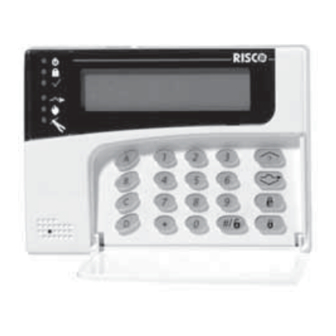
Page 13: Chapter 2: Your Keypad
Chapter 2: Your Keypad As a user of your security system, you'll need to be primarily concerned with the keypad. This section discusses the keypad's visual indicators and the use of its keys. Each keypad in the system is assigned to a particular partition, meaning that commands entered in a keypad are implemented only in the partition to which it is assigned. -
Page 14: Led Indicators
LED Indicators The six LED indicators found at the upper left provide typical system indications, as discussed below. Some indicators have additional functions, which are explained later on. NOTE: If required, the system status can be hidden by setting the keypad to Hidden LCD mode. -
Page 15: Arm/Led
Arm/ The Arm/ LED indicates whether or not the system's intrusion detectors are armed. Condition Description The system's intrusion detectors are armed; subsequent violations of a protected point or area (e.g. a door, a window, unauthorized motion) will result in a burglar alarm The intrusion function of the system is disarmed. -
Page 16: Bypass/Led
Bypass/ The Bypass/ LED is normally lit when Stay mode is selected. Condition Description At least one intrusion zone is bypassed, or Stay mode is selected. All zones are operating normally and the system is in Arm mode. Fire/ When lit, the Fire/ LED indicates that the system is experiencing a fire alarm. -
Page 17: Zone Leds
Zone LEDs The Zone LEDs indicate the status of each of the system's intrusion zones. For LCD keypads, the display indicates the zone's number and label. Condition Description System Disarmed System Armed An alarm has occurred in the indicated zone. The corresponding zone is secured. -
Page 18: Control Keys
Control Keys The functions of the control keys on the keypad vary according to the mode being used. The following table lists the functions of the keys in Normal Operation mode and when using the User Functions menu: Normal Operation User Functions Activates the User Exits from the current menu... -
Page 19: Quick Key Operation
The annunciation that results during these emergency alarms, along with other system sounds, is described on page 68. If your system has been programmed to do so, it will communicate any or all of these alarms to the Monitoring Station monitoring your installation. System programming also determines whether these emergency alarms will be audible and/or capable of being communicated to the Monitoring Station. -
Page 20: Chapter 3: Arming And Disarming The System
Chapter 3: Arming and Disarming the System Arming Arming your system enables its intrusion detectors to trigger an alarm when violated. Remember, fire protection and the protection offered by the keypad's emergency keys are always armed and always available. Your ProSYS offers the following kinds of arming: Away, page 20 Stay, page 21 Partition, page 22... -
Page 21: Stay Arming
NOTE: If you make a mistake, the keypad produces three short beeps. If so, press quickly and re-enter the above sequence correctly. All persons are to exit except the person arming THE JONESES THE JONESES the system. Leave the premises and close the ARM: EXIT = 0:45 ARM: EXIT = 0:45 door. -
Page 22: Partition Arming
If required, leave the premises and close the THE JONESES THE JONESES door. HOME: EXIT = 0:45 HOME: EXIT = 0:45 During the Exit Delay time period, the keypad beeps, the Arm/ LED flashes, and the Bypass/ LED lights, indicating that the interior zones are being bypassed. -
Page 23: Arming Multiple Partitions
Arming Multiple Partitions Only users that have been defined to operate multiple partitions during the system installation can operate more than one partition and arm/disarm all partitions at once. To arm multiple partitions: Check the Ready / LED on your keypad. If it is lit or flashing, the system is READY to be armed. -
Page 24: Group Arming
Group Arming Group arming enables you to arm a number of zones within a partition, using the Function keys. Ask your installer about defining groups. To arm a group (if the system has one partition): Enter your code, followed by the Function key corresponding to the group(s) you want to arm. -
Page 25: Force Arming
Arm (Away) and Disarm modes. Access Control Arming If your system is equipped with RISCO Group's Access Control, you can arm and disarm the system from the Access Control reader. Refer to the Access Control User's Manual for more information. -
Page 26: Disarming
Disarming Disarming your system deactivates its detectors. Remember, fire protection and the protection offered by the keypad's emergency keys are always armed and always available. Your ProSYS offers the following kinds of disarming: System, below Silencing an Alarm, page 26 Partition, page 27 Duress, page 28 Fire Alarm, page 29... -
Page 27: Partition Disarming
For an LCD keypad: The Arm/ LED is flashing, and the display shows the disturbed zone. Enter your user code and press . If an alarm occurred, the Arm/ LED and the corresponding Zone LED will flash for the Alarm Memory period of about 60 seconds. If you are using an LCD keypad, scroll through the list of alarmed zones. -
Page 28: Duress Disarming
For an LCD keypad, scroll with the or the key to the required partition (or enter the partition's number). Press to confirm. A confirmation message will be displayed for several seconds. Repeat the above steps to disarm other partitions. Examples: To disarm partition 3 with code 1234: 1-2-3-4 To disarm ALL partitions:... -
Page 29: Disabling The Fire Alarm (Switch Auxiliary)
To disarm using a duress code: If outside the premises, open an "entry" door. The keypad(s) beeps, indicating that the Entry Delay time period has begun. Enter your duress code and press . The system is disarmed, and a silent alarm is sent to the Monitoring Station. Disabling the Fire Alarm (Switch Auxiliary) Disarming the fire alarm interrupts the power supplied to the system's smoke detector(s) for a predetermined interval, thus resetting and... -
Page 30: Chapter 4: Zone Bypassing
Chapter 4: Zone Bypassing [*] [1] [CODE] [#] [1] When an intrusion zone is not secured, the keypad's Ready/ LED will not light, nor can the system be readily armed. Bypassing a zone enables you to arm a partition even if a zone within that partition is open/not secured. - Page 31 To un-bypass zone 2 only using code 1234, enter: 1-2-3-4 When finished entering zone numbers, press NOTES: All zones are automatically un-bypassed when the system is armed and then disarmed again. The Bypass / LED turns off when arming in Away mode. ProSYS User's Manual...
-
Page 32: Chapter 5: Activating Home Appliances (Uos)
Chapter 5: Activating Home Appliances (UOs) [*] [2] [CODE] [#] [1] You can place a household appliance, such as heating, lighting or an external device, under the control of the ProSYS, where it can be conveniently turned on and off automatically, or by user commands from any system keypad. -
Page 33: Activating Home Appliances From The User Functions Menu
Activating Home Appliances from the User Functions Menu Home appliances can be activated by any user who is assigned a code that is authorized to activate home appliances. To activate home appliances from the User Functions menu: From the User Functions menu, select USER FUNCTIONS: USER FUNCTIONS: [2] Activities. -
Page 34: Chapter 6: Setting Follow Me Destinations
Chapter 6: Setting Follow Me Destinations [*] [2] [7] [CODE] [#] In the case of an alarm or event, the system can initiate a phone call to a designated telephone or pager, send an SMS/email and employ unique tones or messages to express the active event. Your installer defines the type of reporting to a follow me destination. - Page 35 Select one of the following options to define the ENABLE FM NO 1: ENABLE FM NO 1: permission: REMOTE PROGRAM:N REMOTE PROGRAM:N Y: The user on the FM phone can enter the Remote Operations menu and perform arm, disarm, zone bypassing, home appliance activation, FM phone editing, and remote listen and talk operations.
-
Page 36: Chapter 7: User Codes
ProSYS 128 systems can support up to 99 different user codes. ProSYS 40 systems can support up to 60 different user codes. ProSYS 16 systems can support up to 30 different user codes. Your ProSYS was given a Grand Master Code of 1-2-3-4 during manufacturing. -
Page 37: Deleting User Codes
In ProSYS 128 systems, the User Index number is from 00 to 98. In ProSYS 40 systems, the User Index number is from 00 to 59. In ProSYS 16 systems, the User Index number is from 00 to 29. The User Index number 00 belongs to the Grand Master user code. -
Page 38: User Authority Levels
Press [0] followed by CODE 06, USER CODE 06, USER ENTER: 6543 ENTER: 6543 If successful, a single confirmation beep is CODE: 06, USER CODE: 06, USER sounded, and a message is displayed. If not, three ACCEPTED ACCEPTED quick error beeps are sounded. Repeat the above steps for additional codes until SELECT CODE: SELECT CODE:... -
Page 39: Entering User Labels
Level Description MAID Used only for one-time arming and disarming, after which the code is automatically erased and should be redefined. This code is typically used residentially for maids, home attendants, and repairmen who must enter the premises before the owner(s) arrive. UNBYPASS Basic operations to one or more partitions without the ability to bypass zones. -
Page 40: Character Table
Character Table Use the keys on the keypad to produce characters according to the table below. Pressing a particular key toggles between the characters available for that key. The ProSYS permits a total of 74 characters (letters, numbers, and symbols) for use in labeling. NOTES: The data sequence of each key in the following table is suitable only for the English version. -
Page 41: Assigning Double Codes
Assigning Double Codes [*] [5] [CODE] [#] [7] Double codes are a high-security option that ensures that the system is disarmed only by pairs of users. This prevents individual users from disarming the system alone, by making their user code active only if accompanied by their partner's user code. -
Page 42: Chapter 8: Viewing Trouble Conditions
Chapter 8: Viewing Trouble Conditions [*] [3] [1] [CODE] [#] A rapid flashing of the Power/ LED indicates a trouble condition. The following procedure describes how to identify the trouble condition. Refer to the table on page 66 for a list of possible trouble conditions and their descriptions. -
Page 43: Chapter 9: Setting And Changing System Time And Date
Chapter 9: Setting and Changing System Time and Date [*] [6] [CODE] [#] [1] / [2] The correct time and date must be set to ensure proper operation of the ProSYS. Setting and Changing System Time The system time is set and changed from the Set Clocks menu. To set/change the system time: From the User Functions menu, select USER FUNCTIONS:... -
Page 44: Setting And Changing System Date
Setting and Changing System Date The system date is set and changed from the Set Clocks menu. To set/change the system date: From the User Functions menu, select USER FUNCTIONS: USER FUNCTIONS: [6] Clocks. 1) BYPASS 1) BYPASS Select [2] System Date. SET CLOCKS: SET CLOCKS: 1) SYSTEM TIME... -
Page 45: Chapter 10: Defining Weekly Schedules
Chapter 10: Defining Weekly Schedules [*] [6] [CODE] [#] [5] Defining weekly schedules enables you to automate some system operations. This is performed by defining up to two time intervals per day, during which the system automatically performs one of the following functions: Automatic Arming/Disarming, below Automatic UO Activation, page 48... - Page 46 Select a program. SCHEDULER: 01)SCHEDULE 01 Select [1] Arm/Disarm. SCHEDULE 01: 01)ARM/DISARM Select [1] On/Off. ARM/DISARM S:01 1) ON/OFF Use the key to define : SCHEDULE 01: SCHEDULE:ON On : Automatic scheduling is enabled. Off : Automatic scheduling is disabled. Press Press ARM/DISARM...
- Page 47 Select [4] Day/Time. ARM/DISARM S:01 4)DAY/TIME Select [1] Monday. SELECT A DAY SELECT A DAY 1) MONDAY 1) MONDAY -OR- Select [8] All to set the same time intervals for every day in the week. Enter the first time at which the system is armed MON:ARM1 S:01 on Monday.
-
Page 48: Defining A Uo Activation Schedule
Defining a UO Activation Schedule A UO (home appliance) activation schedule automatically activates and deactivates UOs during your required intervals. In each schedule, you can define four UOs to operate simultaneously. When defining a UO activation schedule, you need to define the following parameters: On/Off, UOs, Time Schedule, Vacation, and Label. - Page 49 Specify whether or not the first UO in the list UTIL OUTPUT S:02 should be automatically activated by using the 01)OUTPUT 01 key to enter one of the following characters at the end of the second line in the LCD: Y: Automatically activated.
-
Page 50: Defining A User Limitation Schedule
Enter the second time at which the UO is to be VAC: STOP2 S:02 deactivated on vacation. 00:00 Select [5] Label. UO ON/OFF S:02 5)LABEL Enter a name for the schedule, as described in SCHEDULE LABEL the table on page 40. SCHEDULE 02 Define additional weekly schedules, as required. - Page 51 Select [1] On/Off. USER LIMIT S:03 1)ON/OFF Use the key to define : SCHEDULE 03: SCHEDULE: ON On : Automatic scheduling is enabled. Off : Automatic scheduling is disabled. Press Press USER LIMIT S:03 1)ON/OFF Select [2] Users Number. USER LIMIT S:03 2)USERS NUMBER Specify whether or not each user in the list should USER LIMIT...
-
Page 52: Chapter 11: Programming Function Keys
Chapter 11: Programming Function Keys [*] [9] [CODE] [#] [5] The ProSYS enables you to record a series of commands and assign them to a Function key. When the Function key is pressed, the recorded commands are executed from beginning to end. NOTE: The default function for all Function keys is group arming, as described on page 24. -
Page 53: Using The Arm Key To Program Function Keys
Use the numerical keys or the KEY A CUSTOM KEY A CUSTOM to enter a series of characters representing your required keys, as described on page 53. Each character you enter is displayed in the second line of the LCD. When you have finished entering the series of KEY A CUSTOM KEY A CUSTOM... - Page 54 When your required character is displayed, press to move the cursor to the next field in the LCD, where you can enter the next character in the series. When you have finished entering a series of characters, ensure that the cursor is placed in the field after the last character in the series by pressing again.
-
Page 55: Chapter 12: Proximity Keypad
Chapter 12: Proximity Keypad The proximity keypad enables you to use a proximity tag to arm and disarm the security system or to activate and deactivate home appliances and utilities, such as heating and lights. Proximity tag programming is performed from the User Functions menu. When programming a proximity tag, the following three options are available: (RE)WRITE TAG: Adds a new proximity tag (described below). -
Page 56: Deleting A Proximity Tag By The User Serial Number
Select the user to which you want to assign the SELECT USER: SELECT USER: 00)0 GRAND 00)0 GRAND proximity tag and press NOTE: A display of (****) indicates that a user has already been assigned to a specific proximity tag. Within 10 seconds, approach the proximity tag at a USER XX: APPROACH USER XX: APPROACH... -
Page 57: Deleting A Proximity Tag By The User Tag
Select [2] Del By User. PROX TAG: PROX TAG: 1) (RE)WRITE TAG 1) (RE)WRITE TAG Select the user for which you want SELECT USER: SELECT USER: 00)0 GRAND 00)0 GRAND to delete the proximity tag and press Select [Y] or [N] by using the key and ***DELETE*** ***DELETE***... -
Page 58: Using A Proximity Tag
Using a Proximity Tag When using a proximity tag, the following points regarding assigned partitions are relevant: If your user code is assigned to only one partition, then the partition will arm or disarm automatically. If your user code is assigned to more then one partition, use the keys to select the required partition(s) and press NOTE:... -
Page 59: Chapter 13: Complete Menu Of User Functions
Chapter 13: Complete Menu of User Functions Your ProSYS comes with a variety of selectable user functions that become available when you enter the User Functions mode. This chapter lists the complete menu of user functions, the most frequently used of which are described in detail in previous chapters of this manual. - Page 60 Quick Function Description 2 Activities Utility Output Allows user control of previously designated external devices (e.g. an appliance, a motor-driven garage door, etc.), as described on page 32. Switch Interrupts the power supplied to the system's smoke Auxiliary detector(s) for a predetermined interval, thus resetting and "readying"...
- Page 61 Quick Function Description More... Cancel Sends a "Cancel Alarm" report message to the Monitoring Report Station. This function is used if the alarm was activated by mistake. Overload The Grand Master/Installer /Sub-installer/Manager can use Restore this option to restore overloading of the system’s Switched Power Supply.
- Page 62 Quick Function Description Zone Status Allows the display of all system zones and their current status. Event Log Allows the viewing of significant system events including date and time. Service Info Allows the display of any previously entered service information and the system version. Overview Select between the following LCD keypad display types: Single: The keypad displays the partition name, time, and...
- Page 63 Quick Function Description Diagnostics Enables the Installer/Sub-installer to perform diagnostics tests for: BUS zones, power supply, siren and GSM/GPRS module. More... Walk Test Used to easily test and evaluate the operation of selected zones in your system. Accessory Enables viewing the software version of the BUS zones, Versions switched power supply, siren and GSM/GPRS module.
- Page 64 Quick Function Description Next Arm Used to automatically Away arm a disarmed system at a specific time within the next 24 hours. Next Arm works for one time only since the system deletes the setting after it is acted upon. Next Disarm Used to automatically disarm an armed system at a specific time within the next 24 hours.
- Page 65 Quick Function Description User Defines settings for users, including assigning PIN Settings (Personal Identification Number) codes, assigning users to specific access groups, and deleting users. Open Door Remotely opens any door from any keypad that has previously been defined in the system. NOTE: Refer to the Access Control User's Manual for more information about the Access Control functions.
-
Page 66: Appendix A: System Troubles
Appendix A: System Troubles The following table lists possible trouble conditions, their descriptions, and recommended responses. Trouble Description LED KP Response The capacity of the battery is low Zone 1 LED Contact your dealer. Battery or missing and needs to be flashes. - Page 67 Trouble Description LED KP Response The capacity of the battery is Zone 9 LED Contact your dealer. Battery in flashes. low or missing and needs to Power be recharged or replaced (Requires Supply the 16-Zone Module keypad.) AC Loss The commercial power has been Zone 10 LED Make sure the connection in Power...
-
Page 68: Appendix B: System Sounds
Appendix B: System Sounds In addition to the visual indications provided by your keypad(s), your system is designed to produce audible annunciation after certain events. Depending on the circumstance, such sounds may be made by your system's keypad(s) or sounders (e.g. a siren or bell). NOTES: If defined by your engineer, the internal bell can follow any of the keypad sounds Event... - Page 69 NOTES: 1. Based on decisions made at the time your alarm system was installed, keypads may beep during this type of alarm. 2. Keypad beeps may be disabled at the user's discretion, see Buzzer On/Off under User Menu > Activities 3.
-
Page 70: Appendix C: Scheduling Tables
Appendix C: Scheduling Tables Use the following table to define each of the weekly schedules. Weekly Schedule :_______ Schedule Name: ___________ Schedule Type Parameter Definitions Partition Arm / Disarm Arm Mode: Select Group: Home Group 1st UO No:_________ 3rd UO No:_________ Utility Output 2nd UO No:________ 4th UO No:_________... -
Page 71: Fcc Warning
FCC Compliance Section FCC Part 15 Note This equipment has been tested and found to comply with the limits for a Class B digital device, pursuant to Part 15 of the FCC rules. These limits are designed to provide reasonable protection against harmful interference in a residential installation. - Page 72 7) If trouble is experienced with this equipment US:RISAL10BMD2400, for repair or warranty information please contact RISCO Group USA Inc 2822 NW 79th Ave. Miami, Florida 33122 USA, phone number 305 592 3820, URL: sales@riscogroup.com.
- Page 73 Caution: To ensure proper operation, this equipment must be installed according to the enclosed installation instructions. To verify that the equipment is operating properly and can successfully report an alarm, this equipment must be tested immediately after installation, and periodically thereafter, according to the enclosed test Equipment must be installed according to the manufacturer instructions in order for the alarm dialing equipment to work properly when other equipment connected...
- Page 74 FCC Part 68 Self Declaraion (Telecom): ProSYS User's Manual...
- Page 75 RISCO Group Limited Warranty RISCO Group and its subsidiaries and affiliates ("Seller") warrants its products to be free from defects in materials and workmanship under normal use for 24 months from the date of production. Because Seller does not install or connect the product and because the product may be used in conjunction with products not manufactured by the Seller, Seller can not guarantee the performance of the security system which uses this product.
- Page 76 Contacting RISCO Group RISCO Group is committed to customer service and product support. You can contact us through our website (www.riscogroup.com) or as follows: United Kingdom Tel: +44-161-655-5500 Tel: +1-631-719-4400 technical@riscogroup.co.uk support-usa@riscogroup.com Italy Brazil Tel: +39-02-66590054 Tel: +1-866-969-5111 support@riscogroup.it support-br@riscogroup.com...
Need help?
Do you have a question about the ProSYS 16 and is the answer not in the manual?
Questions and answers
How to delete user quickly