
Related Manuals for Microwave Data Systems MDS TransNET 900


Summary of Contents for Microwave Data Systems MDS TransNET 900
- Page 1 Microwave Data Systems Inc. ™ MDS TransNET 900 Model EL805 Spread Spectrum Data Transceiver MDS 05-2708A01, Rev. B AUGUST 2002...
- Page 2 Tip: Use the last four digits of the Master’s serial number to help avoid conflicts with other MDS TransNET 900 networks. • Set the baud rate/data interface parameters. Default setting is 9600 bps, 8 data bits, no parity, 1 stop bit.
-
Page 3: Table Of Contents
4.2 Configuring Multiple Remote Units .........17 4.3 Tail-End Links ..............17 4.4 Configuring a Network for Extensions ......18 4.5 Using the Radio’s Sleep Mode (Remotes Only) ....18 Sleep Mode Example............18 5.0 OPERATION ................19 MDS 05-2708A01, Rev. B MDS TransNET 900 I&O Guide... - Page 4 HOPTIME [7, 28]............. 31 INIT ................. 31 HREV ................32 KEY ................. 32 MODE [M, R, X] .............. 32 OWM [xxxxx] ..............32 OWN [xxxxx]..............32 PORT [RS232, RS485] ........... 32 PWR [20–30]..............34 MDS TransNET 900 I&O Guide MDS 05-2708A01, Rev. B...
- Page 5 7.4 Performing Network-Wide Remote Diagnostics ....43 7.5 Internal Fuse Replacement ..........44 8.0 RADIO FIRMWARE UPGRADES ..........45 8.1 Obtaining new firmware ..........45 Saving a Web-site firmware file to your PC......45 8.2 Installing firmware in your radio ........45 MDS 05-2708A01, Rev. B MDS TransNET 900 I&O Guide...
-
Page 6: Equipment
Copyright Notice This Installation and Operation Guide and all software described herein are Copyright 2002 by Microwave Data Systems Inc. All rights reserved. Microwave Data Systems Inc. reserves its right to correct any errors and omissions in this manual. MDS Quality Policy Statement We, the employees of Microwave Data Systems, are committed to understanding and exceeding our customer’s needs and expectations. - Page 7 Division 2 wiring methods. FCC Part 15 Notice The MDS TransNET 900™ transceivers comply with Part 15 of the FCC Rules. Operation is sub- ject to the following two conditions: (1) this device may not cause harmful interference, and (2) this device must accept any interference received, including interference that may cause undes- ired operation.
- Page 8 MDS TransNET 900 I&O Guide MDS 05-2708A01, Rev. B...
-
Page 9: About This Manual
“Performing Network-Wide Remote Diagnostics” on Page 43.) The MDS TransNET 900 is housed in a compact and rugged die-cast enclosure that need only be protected from direct exposure to the weather. It contains a single printed circuit board with all necessary components for radio operation. -
Page 10: Model Configuration Codes
• Low current consumption—Less than 8 mA in “sleep” mode. NOTE: Some MDS TransNET 900 radio features may not be available on all radios, based on the options purchased and the applicable regulatory constraints for the region in which the radio will operate. -
Page 11: Spread Spectrum Radios-How Are They Different
How Are They Different? The main difference between a traditional (licensed) radio and the MDS TransNET 900 transceiver is that this unit “hops” from channel to channel many times per second using a specific hop pattern applied to all radios in the network. A distinct hopping pattern is provided for each of the 65,000 available network addresses, thereby minimizing the chance of interference with other spread spectrum systems. -
Page 12: Point-To-Point System
This might be required if an outlying site is blocked from the MAS master station by a natural or man-made obstruction. In this arrangement, an MDS TransNET 900 radio links the outlying remote site into the rest of a licensed MAS system by sending data from that site to an associated MDS TransNET 900 installed at one of the licensed remote sites. -
Page 13: Extending A Transnet Network With A Repeater
MODE R OUTLYING REMOTE SITE Figure 6. TransNET Repeater Network 2.5 Accessories MDS TransNET 900 transceivers can be used with one or more of the accessories listed in Table 1. Contact the factory for ordering details. Table 1. Accessories Accessory Description MDS Part No. -
Page 14: Installation Planning
Master stations are similar, but an omni-directional antenna is normally used instead of a directional type, and a host computer replaces the data terminal equipment. MDS TransNET 900 I&O Guide MDS 05-2708A01, Rev. B... -
Page 15: Site Selection
While the 900 MHz band offers many advantages over VHF and lower UHF frequencies for data transmission, it is also more prone to signal attenuation from obstructions such as terrain, foliage or buildings in the transmission path. MDS 05-2708A01, Rev. B MDS TransNET 900 I&O Guide... -
Page 16: Conducting A Site Survey
Factors such as terrain, distance, transmitter power, receiver sensitivity, and other conditions are taken into account to predict the performance of a proposed system. Contact MDS for more information on path study services. MDS TransNET 900 I&O Guide MDS 05-2708A01, Rev. B... -
Page 17: A Word About Radio Interference
20 dB of attenuation to interference can be achieved by using horizontal polarization. 4. Multiple MDS TransNET 900 systems can co-exist in proximity to each other with only very minor interference as long as they are each assigned a unique network address. -
Page 18: Antenna & Feedline Selection
At remote sites and point-to-point systems, a directional Yagi antenna (Figure 9), is generally recommended to minimize interference to and from other users. Antennas are available from a number of manufacturers. MDS TransNET 900 I&O Guide MDS 05-2708A01, Rev. B... -
Page 19: Feedlines
0.64 dB 1.28 dB 3.84 dB HELIAX 1 1/4 inch 0.10 dB 0.48 dB 0.95 dB 2.85 dB HELIAX 1 5/8 inch 0.08 dB 0.40 dB 0.80 dB 2.4 dB HELIAX MDS 05-2708A01, Rev. B MDS TransNET 900 I&O Guide... -
Page 20: How Much Output Power Can Be Used
6 dBi. The allowable level is dependent on the antenna gain, feedline loss, and the transmitter output power setting. Power considerations for the MDS TransNET 900 are discussed below. In some countries, the maximum allowable RF output may be NOTE: limited to less than 1 watt (e.g., 100 mW / +20 dBm). -
Page 21: Installation
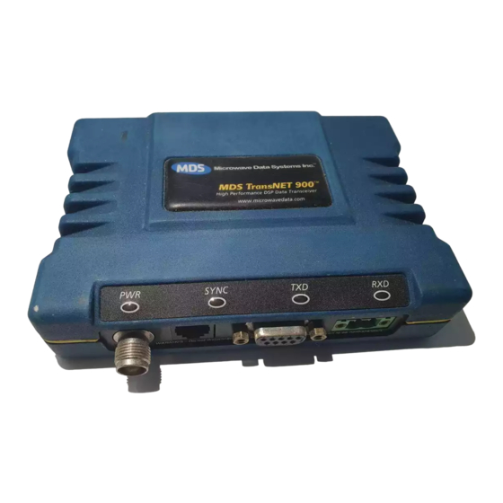
Items ar not shown at the same scale. User documentation will be provided as a paper manual and/or as a PDF on the “MDS TransNET 900™ Support Package CD” (P/N 03-2708A01). The CD includes: • Installation & Operation Guide in PDF (a.k.a. Adobe Acrobat™) •... - Page 22 Invisible place holder 2.75 (7.0 cm) 6.63 (16.64 cm) 1.62 (4.15 cm) Figure 11. Transceiver mounting dimensions Figure 12 shows the four connectors on the MDS TransNET 900 and their functions. Invisible place holder Antenna Data Primary Power (Payload) (6–30 Vdc) Diagnostic (Communications) Figure 12.
- Page 23 The radio must be used only with negative-ground sys- CAUTION tems. Make sure the polarity of the power source is cor- rect. The unit is protected from reverse polarity by an POSSIBLE internal diode and fuse. EQUIPMENT DAMAGE MDS 05-2708A01, Rev. B MDS TransNET 900 I&O Guide...
- Page 24 ADDR Each radio in the system must have the same network address. Tip: Use the last four digits of the master’s serial number to help avoid conflicts with other users. MDS TransNET 900 I&O Guide MDS 05-2708A01, Rev. B...
-
Page 25: Configuring Multiple Remote Units
4.3 Tail-End Links A tail-end link is established by connecting an MDS TransNET 900 radio “back-to-back” with another radio such as a licensed MDS x710B Series transceiver. This can be used to link an outlying remote site into the rest of an MAS network. -
Page 26: Configuring A Network For Extensions
4.4 Configuring a Network for Extensions The installation and configuration of an MDS TransNET 900 network with Extensions is straight-forward with only a few unique parameters that need to be considered and set at each unit. In every network there can be only one Master station. It will serve as the sole gateway to the outside world. -
Page 27: Operation
Complete instructions for using the commands referenced in this manual are provided in “RADIO PROGRAMMING” on Page MDS 05-2708A01, Rev. B MDS TransNET 900 I&O Guide... -
Page 28: Antenna Aiming
For sustained operation at 115200 bps, use the following settings: SAF OFF FEC OFF REPEAT 0 RETRY 0 HOPTIME 28 MDS TransNET 900 I&O Guide MDS 05-2708A01, Rev. B... -
Page 29: Baud Rate Setting
(P/N 06-4059A01) is designed for use with a PC connected to the radio’s connector through an RJ-11 to DB-9 cable assembly (MDS Part No. DIAG 03-3246A01). A cable of this type may be constructed using the information shown in Figure 20 on Page MDS 05-2708A01, Rev. B MDS TransNET 900 I&O Guide... -
Page 30: User Commands
SAF [ON, OFF] Enables/disables the store-and-forward func- Details, page 35 tion for the network controlled by this Master unit. SKIP [NONE, 1...8] Skip one or more frequency zones Details, page 36 MDS TransNET 900 I&O Guide MDS 05-2708A01, Rev. B... -
Page 31: Owner's Name)
Details, page 32 (30 characters maximum) PORT [RS232, RS485] Data port (DATA connector) interface signal- Details, page 32 ing mode: RS232 or RS485 PWR [20–30] Forward power output in dBm. Details, page 34 MDS 05-2708A01, Rev. B MDS TransNET 900 I&O Guide... -
Page 32: Extension)
Details page 28 BAUD 9600 8N1 BUFF Data buffering mode: ON = seamless data, Details page 28 OFF = fast byte throughput CODE Security/encryption operational status. Details page 29 “NONE” (Inactive), or “ACTIVE” MDS TransNET 900 I&O Guide MDS 05-2708A01, Rev. B... -
Page 33: Port
Received signal strength indicator (dBm). Details page 34 Unavailable at Master unless SETUP is enabled. RXTOT The amount of time (in seconds) to wait before Details page 35 issuing a time-out alarm. MDS 05-2708A01, Rev. B MDS TransNET 900 I&O Guide... -
Page 34: Extension)
Included Extended units in MODE X. (Exten- sions and Remotes only). Details page 38 XRSSI Minimum RSSI level required to preserve syn- Details page 38 chronization with a non-primary radio. (Only meaningful when XPRI is not NONE) MDS TransNET 900 I&O Guide MDS 05-2708A01, Rev. B... -
Page 35: Detailed Command Descriptions
NOTE: It is recommended that the last four digits of the master radio’s serial number be used for the network address. This helps avoid conflicts with other Trans- NET 900 users. MDS 05-2708A01, Rev. B MDS TransNET 900 I&O Guide... -
Page 36: Amask [0000 0000-Ffff Ffff]
DATA RF data frame is processed. Average and typical latency will both be below 10 ms, but idle character gaps may be introduced into the outgoing data flow. MDS TransNET 900 I&O Guide MDS 05-2708A01, Rev. B... -
Page 37: Code [None, 1
A timer value of zero means that data will be sent out the data port without imposing a key-up delay. (Other delays may be in effect from other radio operating parameters.) MDS 05-2708A01, Rev. B MDS TransNET 900 I&O Guide... -
Page 38: Ctshold [0-60000]
19200 or the most DLINK ON, recently programmed value. The default is DLINK 19200 DLINK ON NOTE: BAUD The same baud rate must be entered into the InSite Equipment List’s field. MDS TransNET 900 I&O Guide MDS 05-2708A01, Rev. B... -
Page 39: Dkey
DTYPE [NODE/ROOT] command specifies the radio’s operational characteristics for DTYPE network-wide diagnostics. MDS TransNET 900 uses the following types: • –The most common setting, and the default. This is the basic NODE system radio device-type. Typically, the radio network is comprised of nodes and one root. -
Page 40: Hrev
DATA mode: . This is the port though which the payload data will RS232 RS485 pass. Pin descriptions for EIA-232 are on Page 55 and EIA-485 can be found Page MDS TransNET 900 I&O Guide MDS 05-2708A01, Rev. B... -
Page 41: Alarm Output Sense
Hop-time 7 ms HOPTIME 7 Buffer mode BUFF OFF Retry Count 10 (max. 10 repeats for ARQ) RETRY 10 Repeat Count 3 (downstream repeats) REPEAT 3 Forward Error FEC ON Correction MDS 05-2708A01, Rev. B MDS TransNET 900 I&O Guide... -
Page 42: Pwr [20-30]
RSSI reading will provide meaningful results. It will take several seconds to indicate a change in signal level. The radio stays in RSSI mode until is pressed. ENTER MDS TransNET 900 I&O Guide MDS 05-2708A01, Rev. B... -
Page 43: Rtu [On, Off, 0-80]
When the command is entered, the prompt changes to , and: SETUP SETUP> • Hopping is disabled. • Synthesizer frequencies are reset to the test frequencies specified by the commands described earlier. MDS TransNET 900 I&O Guide MDS 05-2708A01, Rev. B... -
Page 44: Ser
ZONE 1 ZONE 2 ZONE 3 ZONE 4 ZONE 5 ZONE 6 ZONE 7 ZONE 8 902.200 905.400 908.600 911.800 915.000 918.200 921.400 924.600 905.200 908.400 911.600 914.800 918.000 921.200 924.400 927.600 MDS TransNET 900 I&O Guide MDS 05-2708A01, Rev. B... -
Page 45: Sleep [On, Off]
This command sets the unit addressing for network-wide diagnostics. The unit address is factory programmed to the last four digits of the serial number. If re-programmed in the field, the entry must consist of five digits between 10000 and 65000. MDS 05-2708A01, Rev. B MDS TransNET 900 I&O Guide... -
Page 46: Xaddr [0-31]
“skipping” those zones using the command. SKIP Note: If a frequency zone has been skipped, all counts for that zone will be zeros. MDS TransNET 900 I&O Guide MDS 05-2708A01, Rev. B... -
Page 47: Troubleshooting
• Errors in the synchronization qualifiers, , on XPRI XMAP corresponding Remote radios. • must be enabled at the Master MDS 05-2708A01, Rev. B MDS TransNET 900 I&O Guide... -
Page 48: Led Indicators
(or seriously hamper) further operation of the transceiver. With the exception of alarm code 00 (network address not programmed), major alarms generally indicate the need for factory repair. Contact MDS for further assistance. MDS TransNET 900 I&O Guide MDS 05-2708A01, Rev. B... -
Page 49: Alarm Code Definitions
The system is reporting an RSSI reading below –105 dBm. Minor The transceiver’s internal temperature is approaching an out-of-tolerance condition. If the temperature drifts outside of the recommended operating range, system operation may fail. MDS 05-2708A01, Rev. B MDS TransNET 900 I&O Guide... -
Page 50: Troubleshooting Chart
BUFF OFF. BUFF ON insures that no gaps occur in the data, but this comes at the cost of increased latency. c. Make sure HOPTIME is set to 7. MDS TransNET 900 I&O Guide MDS 05-2708A01, Rev. B... -
Page 51: Performing Network-Wide Remote Diagnostics
(MDS P/N 03-3246A01) is required. If desired, an adapter cable may be constructed from scratch, using the information shown in Figure 20 on Page 6. Launch the MDS InSite application at the PC. (Refer to the InSite user’s manual for details.) MDS 05-2708A01, Rev. B MDS TransNET 900 I&O Guide... -
Page 52: Internal Fuse Replacement
Littelfuse #0454002; 452 Series, 2 Amp SMF Slo-Blo fuse (MDS Part No. 29-1784A03). 8. Re-install the covers, interface cables and check the radio for proper operation. Invisible place holder Figure 17. Internal Fuse and Holder Assembly Location MDS TransNET 900 I&O Guide MDS 05-2708A01, Rev. B... -
Page 53: Radio Firmware Upgrades
8.0 RADIO FIRMWARE UPGRADES From time to time, Microwave Data Systems releases new firmware for its radio products. This file can be installed in existing radios to take advantage of engineering improvements or additional features. 8.1 Obtaining new firmware The latest firmware for each radio type may be obtained free from our Web site at: www.microwavedata.com/service/technical/support/downloads/... -
Page 54: Operating Principles And Configuration
Remote will respond. Messages within a hierarchy only travel in one direction at a time. Using SAF will cut the overall data throughput in half, however, multiple networks can be inter-connected with no additional loss in network throughput. MDS TransNET 900 I&O Guide MDS 05-2708A01, Rev. B... - Page 55 Extension radios will split their operating time equally between their Master and Remote personalities. This multi-layered network can be extended indefinitely without additional degradation in system throughput beyond that initially incurred by placing the network in the SAF mode. MDS 05-2708A01, Rev. B MDS TransNET 900 I&O Guide...
-
Page 56: Retransmission And Arq Operation
This command puts all radios in the entire system in a special time-division duplexing mode that alternates between two timeslots. One time slot for data communications upstream and the second for downstream communications. MDS TransNET 900 I&O Guide MDS 05-2708A01, Rev. B... -
Page 57: Configuration Parameters For Store & Fwd Services
9.3 Configuration Parameters for Store-and Forward Services The installation and configuration of an MDS TransNET 900 network with an Extension using SAF is straight-forward with only a few unique parameters that need to be considered and set at each unit. -
Page 58: Store-And-Forward (Saf)
XPRI address Extension XRSSI The minimum RSSI level re- Received Signal quired to preserve synchro- Details page 38 Strength Indicator nization with a non-primary radio. (Ineffective when XPRI is NONE) MDS TransNET 900 I&O Guide MDS 05-2708A01, Rev. B... -
Page 59: Security
MDS takes this matter seriously, and provides several means for protecting the data carried over its wireless products. MDS TransNET 900 radios address this issue primarily through the use of the following items: 1) A proprietary modem/data link layer—Data signals are processed using code and hardware specifically designed by MDS. - Page 60 Third party software tools are available for adding encryption, and these should be considered as part of any advanced encryption scheme. MDS TransNET 900 I&O Guide MDS 05-2708A01, Rev. B...
-
Page 61: Technical Reference
Data Rate: 1200, 2400, 4800, 9600, 19200, 38400, 57600, 115200 bps asynchronous Data Latency: 7 ms typical Byte Length: 10 or 11 bits Maximum Data Transmission: Continuous up to 115200 bps MDS 05-2708A01, Rev. B MDS TransNET 900 I&O Guide... -
Page 62: Diagnostic Interface Connections (Rj-11)
DTE data terminal that supports the EIA/RS-232 or EIA/RS-485 (balanced) format, depending on how the radio was configured at the factory. The radio supports data rates of 1200, 2400, 4800, 9600, 19200, 38400, 57600, and 115200 bps (asynchronous data only). MDS TransNET 900 I&O Guide MDS 05-2708A01, Rev. B... -
Page 63: Pin Descriptions-Rs/Eia-232 Mode
CTS (Clear-to-Send)—Goes “high” after the programmed CTS delay time has elapsed (DCE), or keys an attached ra- dio when RF data arrives (CTS KEY). Reserved for Special Uses (Do not connect) MDS 05-2708A01, Rev. B MDS TransNET 900 I&O Guide... -
Page 64: Pin Descriptions-Rs/Eia-422/485 Mode
• TXD+/TXA is positive with respect to TXD–/TXB when the line output is a “0” Invisible place holder 4-WIRE CONNECTIONS 2-WIRE CONNECTIONS RXD + RXD+/TXD+ RXD – TXD + RXD–/TXD– TXD – Figure 22. EIA-422/485 Wiring Schemes (Left: EIA-422, Right: EIA-485) MDS TransNET 900 I&O Guide MDS 05-2708A01, Rev. B... -
Page 65: Dbm-Watts-Volts Conversion Chart
10.0 -135 10mW -136 2.25 .1µW -137 6.4mW .001nW -138 .500 -139 .445 5.75 -140 .01ƒW .400 3.2mW .355 2.5mW 1.25 .320 2.0mW 1.18 .280 1.6mW 1.00 3.51 .252 1.25mW 0.90 MDS 05-2708A01, Rev. B MDS TransNET 900 I&O Guide... - Page 66 MDS TransNET 900 I&O Guide MDS 05-2708A01, Rev. B...
- Page 67 DCE—Data Circuit-terminating Equipment (or Data Communications Equipment). In data communications terminology, this is the “modem” side of a computer-to-modem connection. By default, MDS TransNET 900™ transceivers are set as DCE devices. Digital Signal Processing—See DSP. DSP—Digital Signal Processing. In the MDS TransNET 900™ transceivers, the DSP circuitry is responsible for the most critical real-time tasks;...
- Page 68 The master and all remotes within a given system must have the same network address. Point-Multipoint System—A radio communications network or system designed with a central control station that exchanges data with a number of remote locations equipped with terminal equipment. MDS TransNET 900 I&O Guide MDS 05-2708A01, Rev. B...
- Page 69 SWR—Standing Wave Ratio. A parameter related to the ratio between forward transmitter power and the reflected power from the antenna system. As a general guideline, reflected power should not exceed 10% of the forward power (≈ 2:1 SWR).Zone—See Frequency Zone. MDS 05-2708A01, Rev. B MDS TransNET 900 I&O Guide...
- Page 70 MDS TransNET 900 I&O Guide MDS 05-2708A01, Rev. B...
-
Page 71: Selection 10
INTERFACE connector 14, 21 RSSI (display received signal strength) 34 data interface wiring for tail-end links 17 RTU (enable/disable internal feedlines 11 RTU) 35 maximum length, recommended 15, RX (set/display test receive frequency) 35 MDS 05-2708A01, Rev. B MDS TransNET 900 I&O Guide... -
Page 72: Setup Mode (Setup Command) 35
DTYPE command (set radio’s network-wide, performing 43 diagnostics type) 31, 43, 44 setup mode (SETUP command) 35 using InSite software for network-wide 43 Display Enable alarm output sense (ASENSE internal RTU (RTU command) 35 MDS TransNET 900 I&O Guide MDS 05-2708A01, Rev. B... - Page 73 6 site selection 7 site survey 8 tail-end links 17 connecting to radio’s diagnostic transmission path 7 port 43 Interference launching InSite application at 43 about 9 performing diagnostics using MDS 05-2708A01, Rev. B MDS TransNET 900 I&O Guide...
- Page 74 (BUFF Radio command) 28 inoperative (troubleshooting received data timeout value (RXTOT chart) 42 command) 35 no synchronization with master test receive frequency (RX (troubleshooting chart) 42 command) 35 MDS TransNET 900 I&O Guide MDS 05-2708A01, Rev. B...
- Page 75 XPRI command (display/set extended DATA INTERFACE connector pin address) 38 descriptions 55 XRSSI command (sets minimum RSSI LED status indicators 19, 40 level to maintain sync. w/non-primary troubleshooting 42 extension radio) 38 MDS 05-2708A01, Rev. B MDS TransNET 900 I&O Guide...
- Page 77 The radio must be properly packed for return to the factory. The original ship- ping container and packaging materials should be used whenever possible. All factory returns should be addressed to: Microwave Data Systems Product Service Department (SRO No. XXXX)
- Page 78 Microwave Data Systems Inc. 175 Science Parkway Rochester, NY 14620 General Business: +1 585 243-9600 FAX: +1 585 242-9620 Web: www.microwavedata.com A product of Microwave Data Systems Inc.
Need help?
Do you have a question about the MDS TransNET 900 and is the answer not in the manual?
Questions and answers