Table of Contents
Advertisement
About This Manual
NAVIGATING BY BOOKMARKS
A "bookmark" is the principal navigation tool in our PDF files. All of a file's bookmarks are avail-
able when the "View Bookmarks and Page" is selected in your PDF viewer. Bookmarks in MDS'
PDF publications will usually list all primary and secondary headings found in the manual. In addi-
tion, there are bookmarks for the covers and other relevant information.
NAVIGATING BY THUMBNAILS
A second navigation tool is the "thumbnails" provided when "Thumbnails and Page" is selected in
your PDF viewer. This is suitable for casual scanning of the book as if you were thumbing through
the paper version. Clicking on the page thumbnail will take your view screen directly to that page.
You can also resize the view box on the thumbnail to change the magnification level and the area
being viewed.
NAVIGATING BY HOTLINKS
Many PDF versions of our manuals are equipped with hotlinks between portions of the docu-
ment. Links in the body are displayed as magenta colored strings of text. When your cursor
is positioned over a hotlink, the open hand will change into a pointing finger. Clicking on the
link location will move you to the associated section of the manual. In some manuals, the
hotlinks are only found in the Table of Contents—one link for each major section. These links
are indicated by magenta boxes with dashed lines.
PRINTING
This file contains all of the pages of the paper manual including the covers and is ready for printing.
The file will image each page exactly as it appears in the paper version if you have a 1200 dpi
printer. Lower resolution printers are supported, but highly detailed illustrations such as sche-
matics may not be as readable.
Some manuals will have 11 x 17 inch foldout pages. These pages will print on the default size of
8-1/2 x 11 inches in the "portrait" orientation scaled to fit on the page. To print the foldouts as they
appear in the paper manual, select 11 x 17 inch ("Tabloid") paper stock and the "landscape" orien-
tation in the page set-up window and print the foldouts separately. (This assumes you have a large
format printer on-line.)
MDS ON THE INTERNET
For information on MDS products, technical support and publication updates, connect to our
Internet Web site at http://www.microwavedata.com/. Click on the address to launch your browser.
175 Science Parkway, Rochester, N.Y. 14620, U.S.A.
Sales & Customer Support: +1 (716) 242-9600
FAX–All Services: +1 (716) 242-9620
World Wide Web: http://www.microwavedata.com/
Advertisement
Table of Contents

Related Manuals for Microwave Data Systems MDS 4310


Summary of Contents for Microwave Data Systems MDS 4310
- Page 1 About This Manual NAVIGATING BY BOOKMARKS A “bookmark” is the principal navigation tool in our PDF files. All of a file’s bookmarks are avail- able when the “View Bookmarks and Page” is selected in your PDF viewer. Bookmarks in MDS’ PDF publications will usually list all primary and secondary headings found in the manual.
- Page 2 MDS 4310 350–512 MHZ RADIO TRANSCEIVER Installation, Operation & Field Maintenance Covering the MDS 4310 Transceiver with the 05-2314Axx PCB, the MDS 4350 & 4355 Packaged Systems and All Basic Options MDS 05-2415A01, Rev. A SEPTEMBER 1994 A CALIFORNIA MICROWAVE DIVISION...
- Page 3 MDS 4310 QUICK START GUIDE Below are the basic steps for installing the MDS 4310 (350—512 MHz) Data Transceiver. The infor- mation in parentheses indicates the chapters in this manual where detailed explanations are found. 1. Verify radio set-up parameters. (Chapters 2 & 3) Check the test data sheets packed with the transceiver to be sure the radio is properly configured for the intended application.
- Page 4 MDS P/N 05-2515A01, Rev. A SEPTEMBER 1994 MDS 4310 350–512 MHz RADIO TRANSCEIVER Including the… MDS 4350 and MDS 4355 PACKAGE MODEL RADIOS INSTALLATION, OPERATION FIELD MAINTENANCE Copyright © 1994 Microwave Data Systems All Rights Reserved MICROWAVE DATA SYSTEMS 175 Science Parkway, Rochester, New York 14620...
- Page 5 If further assistance with this product is required, please contact: MICROWAVE DATA SYSTEMS A Division of California Microwave Incorporated 175 Science Parkway Rochester, New York 14620 Telephone No.: 716-242-9600 FAX No.: 716-242-9620 Copyright © 1994 by Microwave Data Systems All rights reserved.
-
Page 6: Table Of Contents
TABLE OF CONTENTS CHAPTER 1—GENERAL INTRODUCTION ------------------------------------------------------------------------------------------------------ 1-1 APPLICATIONS-------------------------------------------------------------------------------------------------------- 1-1 TERMS “ANALOG” AND “DIGITAL” ---------------------------------------------------------------------------- 1-2 MDS 4310 MODULATION TECHNIQUES ----------------------------------------------------------------------- 1-2 MICROCONTROLLER FEATURES ------------------------------------------------------------------------------- 1-2 SOFT CARIER DEKEY ----------------------------------------------------------------------------------------------- 1-3 CONTROL INPUTS AND OUTPUTS ------------------------------------------------------------------------------ 1-3 MODEL NUMBER CODES -------------------------------------------------------------------------- 1-4... - Page 7 CHAPTER 3—PROGRAMMING AND DIAGNOSTICS INTRODUCTION ------------------------------------------------------------------------------------------------------ 3-1 TERMINAL CONNECTION AND STARTUP ------------------------------------------------------------------- 3-1 Opening The Diagnostic Channel -------------------------------------------------------------------- 3-3 CAPABILITIES OF THE HHT -------------------------------------------------------------------------------------- 3-4 Review Operating Parameters and Diagnostic Information -------------------------------------- 3-4 Setting the Operating Parameters--------------------------------------------------------------------- 3-5 Program User Information ---------------------------------------------------------------------------- 3-5 USING THE HAND-HELD TERMINAL -------------------------------------------------------------------------- 3-5 Command Syntax --------------------------------------------------------------------------------------- 3-5 Shift Key ------------------------------------------------------------------------------------------------- 3-5...
- Page 8 CHAPTER 5—THEORY OF OPERATION RECEIVE FRONT END ----------------------------------------------------------------------------------------------- 5-1 HIGH IF ------------------------------------------------------------------------------------------------------------------ 5-1 LOW IF ------------------------------------------------------------------------------------------------------------------- 5-1 RECEIVE AUDIO ------------------------------------------------------------------------------------------------------ 5-1 SQUELCH --------------------------------------------------------------------------------------------------------------- 5-2 POWER SUPPLY ------------------------------------------------------------------------------------------------------- 5-2 TRANSMIT POWER AMPLIFIER ---------------------------------------------------------------------------------- 5-3 ANTENNA SWITCH -------------------------------------------------------------------------------------------------- 5-3 DIRECTIONAL COUPLER------------------------------------------------------------------------------------------- 5-3 KEYLINE AND CONTROL CIRCUITS --------------------------------------------------------------------------- 5-3 RADIO DISABLE ------------------------------------------------------------------------------------------------------ 5-3 AUDIO/DATA MODULATION INPUT SWITCHING ---------------------------------------------------------- 5-4...
- Page 9 APPENDIX D—REMOTE MAINTENANCE MODULE INTRODUCTION ----------------------------------------------------------------------------------------------------- D-1 OPERATION ---------------------------------------------------------------------------------------------------------- D-1 MODULE ADJUSTMENTS & CALIBRATION ---------------------------------------------------------------- D-2 DETERMINING THE PRESENCE OF A REMOTE MAINTENANCE MODULE ----------------------- D-2 INSTALLATION & REPLACEMENT ---------------------------------------------------------------------------- D-3 TESTING THE LOOPBACK CODE ------------------------------------------------------------------------------ D-4 TROUBLESHOOTING ---------------------------------------------------------------------------------------------- D-4 THEORY OF OPERATION ----------------------------------------------------------------------------------------- D-5 APPENDIX E—ORDER WIRE MODULE INTRODUCTION ------------------------------------------------------------------------------------------------------ E-1...
- Page 10 Summary ---------------------------------------------------------------------------------------------- G-13 RS-232 Digital Interface Connections ------------------------------------------------------------ G-13 Additional Interface Connections ------------------------------------------------------------------ G-14 Order Wire Audio Alignment ---------------------------------------------------------------------- G-14 APPENDIX H—MDS 4310-HL DATA TRANSCEIVER FOR USE IN HAZARDOUS LOCATIONS INTRODUCTION ----------------------------------------------------------------------------------------------------- H-1 CONDITIONS OF APPROVAL ------------------------------------------------------------------------------------ H-1 APPENDIX I—CANADIAN CERTIFICATION...
- Page 11 Figure 4-7. Remote Maintenance Module -------------------------------------------------------------------------- 4-19 Figure 4-8. Remote Maintenance Screen --------------------------------------------------------------------------- 4-23 Figure 4-9. MDS 4310 Transceiver PC Board Test Points and Adjustments --------------------------------- 4-25 Figure 5-1. MDS 4310 Transceiver Block Diagram --------------------------------------------------------------- 5-7 Figure A-1. 1200 bps Modem PC Board --------------------------------------------------------------------------- A-1 Figure A-2.
- Page 12 Figure F-5. Analog Interface Assembly 03-1105A21 ------------------------------------------------------------- F-9 Figure F-6. MDS 4350 Packaged System Wiring Diagram with 03-1467A21 RS-232/TTL Interface ---------------------------------------------------------- F-13 Figure F-7. RS-232/TTL Interface Assembly 03-1467A21 ---------------------------------------------------- F-15 Figure G-1. MDS 4355 Interior (AC Version) with Fiberglass Enclosure Removed ------------------------- G-1 Figure G-2.
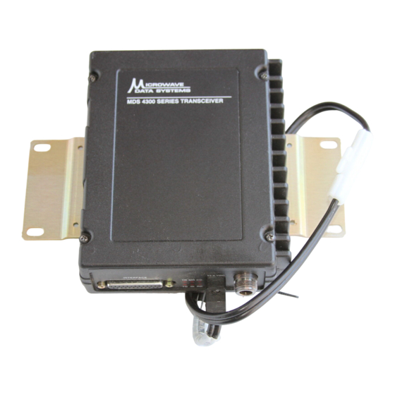
- Page 13 This manual covers three models in the MDS 4300 Series of 450 MHz radio transceivers. The MDS 4310 is the basic transceiver, and it is the main focus of this manual. The MDS 4350 and MDS 4355 are packaged weatherproof models, which include the MDS 4310 radio plus a power supply, back-up battery and interface/utility board, all mounted in a NEMA 4 enclosure.
-
Page 14: Chapter 1-General
12.5 kHz and 25 kHz channels within this range. The MDS 4310 Transceiver can be supplied with a MDS 2314Axx main PC board or a MDS 2013Axx main PC board. Although the two PC boards are similar, this manual covers transceivers with the 2314Axx main PC board. -
Page 15: Terms "Analog" And "Digital
Alternatively, an external modem can be used for controlling AFSK transmission. The MDS 4310 is capable of interfacing with data equipment at standard rates between 50 and 4800 bits per second (bps) with an asynchronous interface to the local terminal unit. The MDS 4310 provides a synchronous or asynchronous interface at data speeds of 1200, 4800 and 9600 bps with one of the optional FSK modems installed internally. -
Page 16: Soft Carier Dekey
The soft carrier dekey feature can be selected or modified by using the HHT. CONTROL INPUTS AND OUTPUTS Four control inputs and outputs are provided on the MDS 4310 Data Transceiver’s 25-pin “D” connector. They are: INTERFACE Receiver Squelch. -
Page 17: Model Number Codes
Figure 1-1. MDS 4310 Model Number Codes MAIN PRINTED CIRCUIT BOARD PCB VARIATIONS The MDS 4310 Transceiver may be equipped with a 2314Axx main PC board or a 2013Axx main PC board. The significant difference is the frequency range. Although the two PC boards are similar, this manual covers transceivers with the 2314Axx main PC board which has a frequency range of 350 to 512 MHz. -
Page 18: Specifications
PRINTED CIRCUIT BOARD MODEL LABEL Figure 1-2. Printed Circuit Model Number Location SPECIFICATIONS: MDS 4310 DATA TRANSCEIVER (2314 MAIN PC BOARD) General Frequency Range: 350–512 MHz (Nominal) Operating Bands— 350–370 MHz, 370–390 MHz, 390–410 MHz, any one of eight: 406–430 MHz, 430–450 MHz, 450–470 MHz, 470–490 MHz, and 490–512 MHz... - Page 19 General Continued Model 4350 and 4355 Packaged Radios Voltage: 120/220 Vac with 5 ampere-hour Battery Back-up (Standard) 12, 24, 48, & 125 Vdc (Optional) DC Supply: Positive, Negative; Floating Ground with 24, 48, & 125 Vdc TX Power Consumption: 50 watts maximum at rated output RX Power Consumption: 5 watts maximum Transient Protection:...
- Page 20 Power Output: 5 Watts/+37 dBm (standard) at the Connector ANTENNA Adjustable down to 0.5 watt/+27 dBm Duty Cycle: 100%/Continuous Output Impedance: 50 Ohms Forward & Reflected Power Detector: Built-in ± 0.00015% (1.5 PPM), –30°C to +60° C, Frequency Stability: For All Models RF Channel Bandwidth: 12.5 kHz (25 kHz Compatible) Spurious &...
- Page 21 Receiver Frequency Range: 350–512 MHz (Nominal) Operating Bands— 350–370 MHz, 370–390 MHz, 390–410 MHz, any one of eight: 406–430 MHz, 430–450 MHz, 450–470 MHz, 470–490 MHz, and 490–512 MHz Frequency Programming: Programmable in 6.25 kHz increments to any channel pair in radio operating sub-band. Type: Double Conversion Superheterodyne ±0.00015% (1.5 PPM) –30°...
- Page 22 Diagnostics & Programming Interface (through connector) INTERFACE Signaling Standard: RS-232C Interface Connector: DB-25 I/O Devices: • MDS Hand-Held Terminal • IBM PC or compatible computer with CGA, EGA, VGA or Hercules Graphics™, DOS 2.0 or later and 640K of memory. System Data Characteristics (through connector) INTERFACE...
-
Page 23: Optional Equipment, Accessories And Certifications
Contact MDS for information on availability and governmental approvals in other countries. OPTIONAL EQUIPMENT, ACCESSORIES and CERTIFICATIONS The MDS 4310 Data Transceiver can be supplied with the following options. For information on adding options to MDS radios, please contact the MDS Marketing Department. -
Page 24: 1200 Bps Bell 202T Modem
Division 2, hazardous locations. Please consult with the MDS Marketing Department for further information on these models. 1200 BPS Bell 202T Modem (Internal)—P/N 03-1815A01 The internal AFSK Bell 202T compatible modem is available for low speed data requirements. It is used at slower standard speeds (30–1200 bps) and provides compatibility in a radio system operating with non-MDS brand analog radios. -
Page 25: Hand-Held Terminal
Remote Maintenance Module Continued When Mode 1 (Local Diagnostics) is enabled, the following parameters are available: • RSSI • Forward and reflected transmit power • VSWR • Transceiver internal ambient temperature • Phase lock loop (PLL) lock condition • Primary power and internally regulated voltages This information is available locally through the HHT or a PC running MDS Remote Diagnostic software (P/N 06-1972A01) In Mode 2: Advanced Diagnostics mode, the diagnostics information available locally can... -
Page 26: Ttl To Rs-232 Converter Assembly
Remote Maintenance Module or Diagnostic & Loopback Module TRANSCEIVER PC BOARD BOTTOM INTERFACE COVER CONNECTOR LED ANNUNCIATOR DISPLAY DC POWER INPUT DETACHABLE & ADJUSTABLE ANTENNA MOUNTING BRACKETS (2) Figure 1-3. MDS 4310 Transceiver—Major Assemblies MDS 05-2415A01, Rev. A GENERAL 1-13... - Page 27 This page intentionally blank 1-14 GENERAL MDS 05-2415A01, Rev. A...
-
Page 28: Chapter 2-Installation
OVERVIEW The MDS 4310 data transceiver is designed to be part of a data communications system. Three critical objectives must be met during the installation—a good antenna system, adequate stable primary power and the correct interface between the transceiver and the external data equipment. -
Page 29: Surface Mounting
SURFACE MOUNTING Using the supplied bracket, the MDS 4310 Data Transceiver can be mounted in any position inside heated or unheated equipment buildings. For outdoor mounting, the unit must be mounted in either a customer-supplied weatherproof housing or the MDS 4350/MDS 4355 packaged enclosure. -
Page 30: Figure 2-1. Mounting Dimensions-Front View
To install the unit: Choose a location to allow easy access to the fasteners so that the entire unit can be readily removed for service or replacement, yet allows viewing of the LED indicators on the front of the case. Fasten the brackets to the mounting surface with a 1/4 inches (M6) bolt, screw, or lag screw (fasteners not provided) through the four holes in the mounting bracket. -
Page 31: External Connections
Connector ANTENNA Connector on the front panel of the MDS 4310 is the RF connector. See Figure ANTENNA 2-1. It is an industry standard female type “N” connector and mates with a standard type “N”... -
Page 32: Figure 2-3. External Connections
This time can be modified by the user to suit specific system timing requirements with the HHT. When equipped with an optional internal modem, the MDS 4310 “SMART” Data Transceiver interfaces directly to any data terminal or RTU that supports the Bell 202, RS-232 format. -
Page 33: Table 2-1. Db-25 Interface Connector Pin Functions
When using an internal modem, other pin functions of the DB-25 connector, such INTERFACE as PTT, Receive Audio, Transmit Audio and RSSI are still active and should normally be left open (unterminated). Connecting these pins to a computer terminal that also uses these pins for auxiliary connections can cause improper operation. -
Page 34: Interface Connector Pin Functional Descriptions
NOTES For Table 2-1 The radio is configured as DCE (data circuit-terminating equipment), as opposed to DTE (data terminal equipment). When using an internal modem, other pin functions of the DB-25 INTERFACE connector, such as PTT, Receive Audio, Transmit Audio and RSSI, are still active and should normally be left open (unterminated). - Page 35 PIN 6: DSR—Data Set Ready Provides a + 8 Vdc DSR signal to external terminal through a 1 kΩ resistor. PIN 7: Signal Ground Connected to ground (negative supply potential) at the radio PC board. PIN 8: DCD—Data Carrier Detect with internal modem Provides an RS-232 compatible output.
- Page 36 PIN 11: Receiver Filtered Audio Output—Line Level (Continued) If the distance to the modem or RTU is greater than five feet (1.52 meters), use a twisted pair of conductors to make the connection. Connect one end of the pair to the audio input terminals of the modem or RTU and the other end to pins 11 and 7 of the connector.
-
Page 37: Figure 2-4. Received Signal Strength Indicator Calibration Chart (Typical)
PIN 19: +8 Vdc Regulated Source This pin provides a convenient source of regulated 8 Vdc at 10 mA for powering external equipment. PIN 20: No Connection PIN 21: RSSI (Received Signal Strength Indicator) A received signal strength indicator (RSSI) output is provided on this pin to aid in steering antennas and monitoring changes in relative signal strength of received signals. -
Page 38: Front Panel Indicators
This pin is used only on applications requiring a synchronous interface with an external device controlling the timing of the transmitted bits. The most common application of this pin is where the MDS 4310 is connected to an external high speed modem. In this case, a cross-over (“null-modem”) cable is required that connects Pin 17 (RC) from one modem to Pin 24 (ETC) of the other, and vice versa. -
Page 39: Transceiver Configuration Jumpers
TRANSCEIVER CONFIGURATION JUMPERS The 4310 Transceiver has three jumper blocks that configure the transceiver. The following sections describe the use and function of these jumpers. J11—TTL/RS-232 and LED Enable Jumpers Jumper J11 configures two functions; the front panel LEDs and interface signal levels. See Figure 2-5 and Table 2-4 for jumper details. -
Page 40: J14-Receiver Audio Output Phase
J16 Pins 1–2 and J16 Pins 3–4 must be jumpered for normal remote operation. The Full Duplex Option Connector is used only when the MDS 4310 is paired with another MDS 4310 transceiver for full duplex operation. Do not move these jumpers from the factory settings without first consulting MDS Systems Engineering. -
Page 41: The Role Of The Modem
INTERFACE POWER REQUIREMENTS The MDS 4310 Transceiver can be powered from any source with a nominal terminal voltage between 12 and 15 volts direct current and capable of supplying a minimum of 2.5 amperes. NOTE Under no circumstances should the nominal supply voltage drop below 10.5 volts or rise above 16.5 volts. -
Page 42: Antennas And Feedlines
The battery used should be designed for deep discharge service. Such batteries are available from industrial battery distributors and retail outlets, where they are sold as power sources for recreational vehicles or for electric trolling motors for sport fishing. ANTENNAS AND FEEDLINES Antenna Selection and Mounting A directional Yagi or corner reflector antenna is required by the FCC for use on all remote stations to minimize interference to and from nearby systems. -
Page 43: Feedline Selection
NOTE A Yagi antenna can be oriented for either horizontal or vertical polarization. All systems using a gain type omni-directional antenna at the master station employ vertical polarization of the signal; therefore the remote antenna must also be vertically oriented, with its elements perpendicular to the earth’s surface. If the antenna is mounted with its elements parallel to the ground (horizontal polarization), the received signal strength can be reduced by 20 dB or more. -
Page 44: Feedline Installation
Feedline Installation It is absolutely essential that the feedline connectors be installed in accordance with the manufacturers’ instructions for the particular type of connector used. Also, any special tooling required for mounting the connectors must be used, to ensure maximum mechanical and electrical reliability. - Page 45 This page intentionally left blank. 2-18 INSTALLATION MDS 05-2415A01, Rev. A...
- Page 46 CHAPTER 3 PROGRAMMING AND DIAGNOSTICS INTRODUCTION A significant feature of the 4310 Transceiver is the ability to accomplish many radio programming and diagnostic tasks through software commands issued from a Hand-Held Terminal (HHT). Software control of the transceiver allows measurement and adjustment without removing the top cover.
-
Page 47: Figure 3-1. Hand-Held Terminal Connected To The Mds 4310 Transceiver
This completes the HHT startup procedure. After a five second “quiet time” (no reception of radio signals), the Diagnostics Channel may be opened as outlined below. Figure 3-1. Hand-Held Terminal Connected to the MDS 4310 Transceiver Figure 3-2. MDS 4355 Packaged Transceiver PROGRAMMING AND DIAGNOSTICS... - Page 48 Special Instructions for Radios Configured as TTL In most cases, an HHT can be plugged directly into the radio’s INTERFACE connector and used immediately. However, in some cases, the INTERFACE connector may have been configured for TTL operation (as opposed to the more common RS-232 format) using the radio’s J11 jumper.
- Page 49 CAPABILITIES OF THE HHT With the HHT properly connected to the transceiver’s DB-25 connector, the INTERFACE following can be performed. • Review operating parameters and diagnostic information • Set the operating parameters of the radio • Program user information All of these tasks can be performed with the radio mounted in its final operating position without the need for removing the top cover of the transceiver enclosure.
- Page 50 Setting the Operating Parameters The user can select and set several of the operating parameters of the radio. These parameters include: • Transmit Frequency • Receive Frequency • Time-out Timer Length • Enable or Disable Time-out Timer • Squelch Tail Eliminator Status •...
-
Page 51: Figure 3-2. Hand-Held Terminal Keypad
PROGRAMMING EXAMPLES Refer to Figure 3-2 or an actual HHT for the following discussion. The following is an example of reprograming the MDS 4310 Transceiver in the field, using the HHT. The current parameters of operation are: •... - Page 52 Squelch Tail Eliminator = off • Loopback Code = 1234 The list of steps and commands below will program the MDS 4310 with the required values. Connect the HHT to the transceiver as previously outlined, and open the diagnostics channel if necessary.
- Page 53 PROGRAMMING OWNER’S INFORMATION The information accessible by the commands can be programmed by the user to allow information unique to the radio transceiver or its location to be stored in the EEPROM. Normally, this field is left blank on units as shipped from MDS. To program these fields, proceed according to the following directions: Open the diagnostics channel.
- Page 54 Diagnostics and Control System Software User’s Guide (MDS P/N 05-1919A01). Since it is possible to have MDS 4310 radios of different capabilities installed in the same system it is very important to know the exact profiles of each unit. The following are descriptions of the various diagnostic capabilities available for the MDS 4310 Transceiver.
-
Page 55: Table 3-1. Diagnostic And Control Capabilities
This is the highest level of diagnostics and control capability available for the Maintenance MDS 4310 transceiver. With Remote Maintenance enabled, all of the above diagnostic capabilities are available and, in addition, many of the radio’s parameters can be adjusted either locally with an HHT or over the RF channel with a personal computer running MDS 2000 Diagnostic and Control System software. -
Page 56: Table 3-2. Programming And Test Commands
PROGRAMMING AND TEST COMMANDS Table 3-2 contains a list of all HHT programming and diagnostics commands. NOTE Some command strings in Table 3-2 include an underscore “_” symbol to denote a key press. The underscore is a visual SPACE reminder only, and should not be entered. Table 3-2. - Page 57 Table 3-2. Programming and Test Commands—Part 2 of 3 DIAGNOSTIC AND TEST MODES TEST MODES KEY ..Keys the transmitter TEST_5 ..Disables VCO (Transmit modulation enabled) TEST_6 ..Enables VCO DKEY ..Dekeys the transmitter TEST_7 ..Turns on modem test tones and keys the TEST_1 ...
-
Page 58: Figure 3-3. Hht Initialization Display
Table 3-2. Programming and Test Commands—Part 3 of 3 REMINDERS • All command entries end with the ENTER key. • Use the SHIFT key to access numbers; press again to return to characters. • Square cursor ( ) – letter mode is selected. •... -
Page 59: Table 3-3. Hand-Held Terminal Operating Defaults
Table 3-3. Hand-Held Terminal Operating Defaults PARAMETER SETTING Re-init HT Baud Rate 1200 Comm bits 8,1, n Parity Error Key Repeat Echo Shift Keys Ctl Chars PROCS Scroll on 33rd Cursor CRLF for CR Self Test SLOW Key Beep Screen size Menu Mode LONG HAND-HELD TERMINAL WIRING... -
Page 60: Figure 3-5. Db-9 To Db-25 Interface Cable Wiring
Cable Wiring for a PC or ASCII Terminal CAUTION When connecting a PC or ASCII terminal to the MDS 4310 Transceiver, use only the required pins specified below. Do not use a straight DB-25 to DB-25 cable wired pin for pin. - Page 61 This page intentionally left blank. 3-16 PROGRAMMING AND DIAGNOSTICS MDS 05-2415A01, Rev. A...
- Page 62 Unless otherwise noted, the procedures given here apply equally to the MDS 4310 transceiver and the MDS 4350/4355 packaged models. For additional set-up information on the MDS 4350 and MDS 4355, refer to Appendices F and G respectively.
- Page 63 TEST EQUIPMENT REQUIRED Continued Frequency measuring equipment usually requires a “warm-up” period to achieve maximum accuracy; a warm-up period of 30 minutes is not uncommon. Please read the unit’s instruction manual before proceeding with frequency measurements. NOTE FCC regulations require a frequency accuracy of .00015% (1.5 ppm).
- Page 64 shown in Figure 4-1. The transceiver’s connector must be configured for INTERFACE RS-232 operation for proper operation of the emulator. (See “Special Instructions for Radios Configured as TTL” below if your radio has been configured for TTL.) NOTE As an alternative to a Data Terminal Emulator, a “breakout box”...
-
Page 65: Figure 4-1. Remote Data Terminal Emulator Wiring
RADIO TERMINAL TRANSCEIVER EMULATOR STANDBY XMTR KEYED +5 VDC Pin 4 Pin 6 Pin 2 Transceiver Male DB-25 SPACE Interface Connector MARK Connector Figure 4-1. Remote Data Terminal Emulator Wiring SW1 and SW2 mounted inside a small enclosure METHOD ONE SMALL TOGGLE SWITCHES (SPST) SMALL ENCLOSURE... - Page 66 Switch Functions Listed below are the functions of the two toggle switches referred to in Figure 4-1. These functions are called for in many of the test procedures which follow. • Closing SW1 keys the transmitter by setting the RTS line high. •...
-
Page 67: Table 4-1. Main Circuit Board Potentiometer Settings For Remote Maintenance
The following test procedures in this chapter are arranged according to the hardware configuration of the MDS 4310 transceiver. The primary difference between units is the presence of a modem—no modem, 1200 bps modem, 4800 bps modem, or 9600 bps modem. -
Page 68: Introduction
NOTE The transmitter will be turned off by the time-out timer if the transmit period exceeds the programmed time out value. To continue testing, simply unkey and key the transmitter to reset the timer. The factory default value for the time-out timer is 180 seconds. - Page 69 Transmitter Power Output Check Connect a directional wattmeter between the transceiver and the antenna feedline. Connect the HHT to the transceiver and open the Diagnostics Channel. Key the transmitter by entering . This command keys the transmitter until the command is entered (or until the time-out period has been reached). DKEY Check the output power of the transceiver.
-
Page 70: Figure 4-3. Vco Lock Voltage Test Point
VCO sub-assembly. VCO LOOP VOLTAGE TEST POINT ASSEMBLY SHIELD C247 VCO RANGE (THRU SIDE OF SHIELD) Figure 4-3. VCO Lock Voltage Test Point This completes the basic tests of the MDS 4310 Transceiver. MDS 05-2415A01, Rev. A FIELD TESTS & ADJUSTMENTS... - Page 71 The receive audio output level of the transceiver is factory-set for 0.7 Vp-p (–10 dBm) at 600 Ω, at rated system deviation. If a third party modem is used with the MDS 4310, consult its instruction manual to determine what audio input level the modem needs. Should a...
- Page 72 Secure all cables, providing strain relief if necessary, and check connectors for tightness. This completes the set-up of the MDS 4310 transceiver without a modem installed. TEST PROCEDURE TRANSMIT FREQUENCY, SQUELCH, DEVIATION, AND RECEIVE AUDIO OUTPUT—For Radios with MDS’s Internal 1200 BPS Modem In the following procedures, references to SW1 &...
- Page 73 TEST PROCEDURE (Continued) TRANSMIT FREQUENCY, SQUELCH, DEVIATION, AND RECEIVE AUDIO OUTPUT—For Radios with MDS’s Internal 1200 BPS Modem Set-up Remove the cover from the transceiver by loosening the four captive cover screws and lifting it straight up. Connect the HHT and open the Diagnostics Channel. Connect the transceiver’s connector to the input of the service monitor ANTENNA...
-
Page 74: Figure 4-4. 1200 Bps Afsk Modem
Generate an on-channel signal at –60 dBm (225 µV), with 1 kHz modulation at 2.5 kHz deviation. Adjust the transceiver’s R25 for 1.2 Vp-p ± 0.05 V at U3 pin 8 (on the main transceiver PC board) as read on the oscilloscope. 10. - Page 75 Putting Things Back Together Restore the transceiver’s time-out timer to the original value (if changed) using the command on the HHT. The factory default setting is 180 seconds. PTOT_XXX Reinstall the cover. Reconnect the antenna feedline and reconnect the RTU’s interface cables to the transceiver.
-
Page 76: Configuration
Data Deviation With the transmitter still keyed (SW1 Closed), increase the deviation by rotating R168 clockwise to cause the frequency to shift down from the assigned center frequency by 1.6 kHz ± 75 Hz. If Remote Maintenance is installed, set R168 to its full-clockwise position and use the commands to set the downward frequency INCD... - Page 77 Squelch Adjustment Using an oscilloscope set for DC coupling and 2 V or 5 V per division, observe the Receiver Unsquelched (RUS) signal at Pin 10 of the radio’s connector. INTERFACE Insert an on-channel signal at –120 dBm (.225µV), with a 1 kHz tone and 2.5 kHz deviation.
- Page 78 CONFIGURATION OFF (OPEN) Pin 7 (CLOSED) Figure 4-6. 9600 BPS FSK Modem; MDS P/N 03-1833A01 See Table C-1 in Appendix C for details on switch settings. Transmit Frequency Key the transmitter by raising RTS (SW1 Closed). The TXD line should be at logic low (LED annunciator TD [TXD] off).
- Page 79 Data Deviation ( Continued) Note—There is some interaction between R168 and the TX Frequency adjustment on the TCXO. If the shift is equal in both directions, but exceeds 1.6 kHz, it may be necessary to turn the deviation down slightly and repeat this step. Continue to alternately adjust R168 and the TX Frequency adjustment on the TCXO until equal 1.6 kHz shifts are obtained.
-
Page 80: Figure 4-7. Remote Maintenance Module
TEST PROCEDURE REMOTE MAINTENANCE MODULE— Loopback Code Programming, Mode Selection, Calibration & Testing Introduction The Remote Maintenance Module (Figure 4-7) is a small PC board assembly that mounts vertically into Jacks J5 and J7 of the transceiver PC board. The module contains two adjustable controls—Loopback TX Audio Level (R6), and Temperature Setting (R33). - Page 81 display. (Units shipped from the factory are pre-programmed with a default loopback code consisting of the last four digits of the radio’s serial number.) The displayed loopback code is followed by the characters (uninstalled) or (installed) at the end of the second line in the display to indicate the presence of a Remote Maintenance Module.
- Page 82 factory and the need for field adjustment of this parameter is rare. Nevertheless, instructions are given below. If the temperature calibration is misadjusted, its value in remote (over-the- air) and local diagnostics will be compromised. Measure the temperature at or near the transceiver chassis using a thermometer that is accurate to 1°C.
- Page 83 DTMF to DATA. If the data deviation is 2.7 kHz ±0.2 kHz, proceed to the next step. If not, adjust the MDS 4310 deviation as described in the Field Alignment instructions in this chapter.
-
Page 84: Figure 4-8. Remote Maintenance Screen
14. This completes the Remote Maintenance checkout procedure. For additional information on the Remote Maintenance Module refer to Appendix D. MICROWAVE DATA SYSTEMS -- REMOTE MAINTENANCE ADJUSTMENT Press (Esc) to Exit or Use (Arrow) keys to select and change a Control Setting... - Page 85 This page intentionally blank 4-24 FIELD TESTS & ADJUSTMENTS MDS 05-2415A01, Rev. A...
- Page 86 4A FUSE (THRU SIDE OF SHIELD) TX POWER SQUELCH ANTENNA OUTPUT THRESHOLD Figure 4-9 MDS 4310 Transceiver 2314Axx PC Board Test Points and Adjustments Potentiometer types may differ from those shown. MDS 05-2415A01, Rev. A FIELD TESTS & ADJUSTMENTS 4-25/26...
- Page 88 CHAPTER 5—THEORY OF OPERATION For the following discussion, see Figure 5-1, the radio’s block diagram at the end of this chapter. RECEIVE FRONT END Connector J4 on the main PC board conducts the RF signal from the front panel ANTENNA connector to the antenna switch network.
- Page 89 The output of the squelch gate goes to the modem receive audio amplifier, U5A. U5A is an amplifier with the gain set by potentiometer R25. R25 is used to adjust the receive audio level supplied to the modem and remote maintenance boards. U5D and U5C are an audio lowpass filter that removes noise from the receive audio.
- Page 90 The transmitter can be turned off, independent of microcontroller control, by the synthesizer out-of-lock signal. An out-of-lock condition at the synthesizer will bring the O/L line high, overriding the power control signal TXE2. TRANSMIT POWER AMPLIFIER The power amplifier chain of the transmitter section consists of U40 and U33. U40 is a driving amplifier for U33.
- Page 91 If J1-Pin 12 is grounded U13 and U38 are disabled. Since U38 supplies current to nearly all of the transceiver circuits, current consumption in the transceiver is reduced essentially to zero. This eliminates the need to externally switch the +13 volts applied to the transceiver. AUDIO/DATA MODULATION INPUT SWITCHING One section of U15, switch U15X, controls data appearing at the RXD terminal, Pin 3 of J1, switching between modem data and microcontroller data from U16.
- Page 92 DIAGNOSTICS DATA CONTROL Communications between the microcontroller U16 and an external terminal, PC or the HHT is accomplished by means of the TXD (J1–Pin 2) and RXD (J1–Pin 3). U16 constantly monitors transmit data input on J1–Pin 2, and ignores all data unless the OPEN command from the external programmer is detected or a ground is detected on J1–Pin 23.
- Page 93 compatible output. Transient protection for the five RS-232 I/O lines from J1 is accomplished by means of zener protection diodes. Static discharge or over-voltage condition appearing on J1 will be shunted to ground with these devices before reaching U31. In the data signal interface between the plug-in modem assembly and the main transceiver board (i.e., the plug in modem option), the signals are inverted from standard RS-232 signal polarity.
-
Page 94: Figure 5-1.Mds 4310 Transceiver Block Diagram
Figure 5-1.MDS 4310 Transceiver Block Diagram MDS 05-2415A01, Rev. A THEORY OF OPERATION 5-7/8... - Page 96 Hand-Held Terminal (HHT), refer to Chapter 3—Programming and Diagnostics. Troubleshooting assistance is also available from Microwave Data Systems in Rochester, NY (Telephone No. (716) 242-9600). Please have the complete model number and serial number of the transceiver ready when calling for assistance. Refer to the inside back cover of this manual for more information on obtaining factory assistance.
- Page 97 Transmitter Power Measurement Measure transmitter power output at the connector with an in-line ANTENNA wattmeter or a service monitor. It should not exceed 5 watts. Transmit Modulation Evaluation Check to see that transmit audio connections are properly made. Check transmitter deviation and adjust, if necessary. Transmit Frequency Measurement Check transmit carrier frequency with a service monitor or frequency counter (±...
- Page 98 HHT or PC terminal. If noise from the squelch tail (closing) is interfering with the data flow, then enable the Squelch Tail Eliminator function in the MDS 4310 using the ESTE command with the HHT. (Applies to analog systems only.) Check for excessive length of the interface cable.
- Page 99 This page intentionally blank TROUBLESHOOTING MDS 05-2415A01, Rev. A...
-
Page 100: Figure A-1. 1200 Bps Modem Pc Board
(bps) data rate. It will track input data rates as low 50 bps. With this option mounted within the transceiver enclosure, the MDS 4310 Transceiver can still be pro- grammed through the RS-232 connector, without the need to remove the housing cover. - Page 101 THEORY OF OPERATION (Refer to Figure A-1 and Figure A-2) Modulator The modulator consists of a monolithic function generator integrated circuit, U2, which generates an audio tone whose frequency depends on the state of Pin 9, the data input. A voltage-controlled oscillator is included in the IC, the frequency of which is determined by either R2 or R3.
-
Page 102: Figure A-2. Bell 202T Compatible Modem Block Diagram
LOW PASS FILTER DATA MODULATOR DELAY TX AUDIO OUT MODEM PTT MARK SPACE ADJ. ADJ. MODEM RUS LOW PASS DATA FILTER DEMODULATOR GATE RX AUDIO IN THRESHOLD ADJ. + 10V 10 V REGULATOR REGULATOR On-Board Voltage Regulator & Power + 13V IN + 5V Control Figure A-2. - Page 103 This page intentionally blank APPENDIX A MDS 05-2415A01, Rev. A...
- Page 104 MDS 4300 Series Transceivers, allowing it to be mounted within the transceiver housing. This modem is capable of synchronous or asynchronous operation. With this option mounted within the transceiver enclosure, the MDS 4310 Transceiver can still be programmed via the RS-232 connector, without the need to remove the housing cover.
-
Page 105: Figure B-1. Mds 4800 Bps Modem Block Diagram
bypass jumpers in place of U31 in the TTL configuration. The transmit data is fed into the data processor U6. Level shifting and wave shaping operations cause the data to resemble a smooth audio wave- form. This waveform feeds into the modulation input of the transmitter. Deviation and center frequency are controlled by the transmitter. -
Page 106: Table B-1. Settings For The Mds 4800 Bps Modem's Configuration Switch S1
When an RF carrier is detected, the receiver squelch forces DCD true and the receiver re- ceives the FSK (Frequency Shift Keyed) signal just as it would any FM modulated signal. The recovered audio is fed to the modem board which determines the peak excursion of the received waveform in each direction. - Page 107 This page intentionally blank APPENDIX B MDS 05-2415A01, Rev. A...
- Page 108 This modem is capable of synchronous or asynchronous operation at 9600 bits-per-second (bps). With this option mounted within the transceiver enclosure, the MDS 4310 Transceiver can still be programmed via the RS-232 connector, without the need to remove the housing cover.
-
Page 109: Table C-1. Settings For The Mds 9600 Bps Modem's Configuration Switch S1
Level shifting and wave shaping operations within U6 cause the data to resemble a smooth audio waveform. This waveform feeds directly into the modulation input of the digital transmitter. With no scrambling, a mark (the normal resting state when no data is being sent), is sent by an alternating 10101010 pattern at 9600 bits per second. -
Page 110: Figure C-1. Mds 9600 Bps Modem Block Diagram
NOTE The “Alternate” mode is required if asynchronous data has gaps between characters that are not equal to a multiple of a bit time, or if 1-1/2 stop bits are used. SYNC-ASYNC PROM CONVERTOR RS-232 DATA INTERFACE LOW PASS FILTER SLICER MODEM RX AUDIO... - Page 111 This page intentionally blank APPENDIX C MDS 05-2415A01, Rev. A...
- Page 112 INTRODUCTION The Remote Maintenance feature allows fine-adjustment of several important operating parameters of an MDS 4310 Transceiver either locally with an HHT (or PC terminal), or from a distant location over-the-air using MDS 2000 Diagnostics and Control System Software. This software resides on a personal computer at the system control site.
-
Page 113: Figure D-1. Remote Maintenance Module, P/N 03-1958A01
NOTE An alternative to the HHT is a personal computer running a terminal program, such as PCPLUS™, PROCOMM™, PCTALK™, etc. connected to the radio’s INTERFACE connector. In this case, the program should be set to 1200 bps, eight data bits, parity-none and one stop bit. The keyboard must be set with the caps lock key pressed, as the radio responds only to commands made in uppercase characters. - Page 114 If you are unsure whether a Remote Maintenance Module is installed in the transceiver, open the Diagnostics Channel and enter the command. The display responds with the type of STAT diagnostics that are installed in the transceiver. The forth character will be for “installed”, or for “uninstalled.”...
- Page 115 NOTE Once a loopback code has been entered, typing the L B C command results in a display of the code, followed by the letter to indicated that it is “Installed.” If a loopback code has not been programmed, the letters for “Uninstalled”...
- Page 116 Radio RF TX Power Control U10 is a 100-position 100k EEPOT that controls the radio’s RF TX power. U10 is configured as a ratiometric resistor that sources a voltage to control the transmitter power. The voltage being sourced by the EEPOT is controlled by the micro-controller on the transceiver’s main circuit board.
-
Page 118: Figure E-1. Order Wire Module
Kit P/N: 02-1297A01 INTRODUCTION The Order Wire Module (Figure E-1) is an optional adapter for the MDS 4310 Transceiver which makes two-way voice communications possible for the initial set-up and testing of the radio link. If the Order Wire Module is connected between the transceiver and the RTU, and a telephone handset is plugged into the Order Wire Module, it is possible to listen to the data communications on the channel. -
Page 119: Figure E-2. Order Wire Board Component Layout
THEORY OF OPERATION (Refer to Figure E-2 and Figure E-3) Microphone audio is first pre-emphasized by C-1 and R5. R4 provides current for the carbon microphone typically used in telephone handsets. U1A amplifies and limits the microphone audio, with R17 setting the VOX microphone gain. R19 sets the deviation and is normally set for –10 dBm output to the transmitter. - Page 121 This page intentionally blank APPENDIX E MDS 05-2415A01, Rev. A...
-
Page 122: Conditions Of Approval
FOR USE IN HAZARDOUS LOCATIONS INTRODUCTION The MDS 4310-HL Data Transceiver is available for use in Class I, Division 2, Groups A, B, C, and D Hazardous Locations. Such locations are defined in Article 500 of the National Fire Protection Association (NFPA) publication NFPA 70, otherwise known as the National Electrical Code. - Page 123 This page intentionally blank APPENDIX H MDS 05-2415A01, Rev. A...
-
Page 124: Appendix Icanadian Certification
The Industry Canada approval is valid subject to the restrictions listed below: The MDS 4310 may only be used with a built-in modem at speeds of either 1200, 4800 or 9600 bps. No external modems or other signaling devices using external transmit audio input (Pin 9 of the connector) are permitted. - Page 125 This page intentionally blank APPENDIX I MDS 05-2415A01, Rev. A...
-
Page 126: Appendix Jaudio Processing Module
This function is typically called a VOX function. When installed in the MDS 4310 Transceiver, the Audio Processing Module is mounted in the Option 1 position on the main transceiver board. See Figure J-3. -
Page 127: Alignment
If technical assistance is required, contact MDS, Systems Engineering Department. NOTE When the VOX Function is used in an MDS 4310 Transceiver, the Squelch Tail Eliminator (STE) circuitry on the transceiver’s motherboard should be turned off. The status of this operating parameter can be checked, and if necessary set to OFF, using the Hand-Held Terminal (HHT). - Page 128 In Case of Difficulty... The MDS 4310 Transceiver is designed for long life and trouble-free operation. However, this equipment, as with all electronic equipment may have an occasional component failure. The following information will assist you in the event that servicing becomes necessary.
Need help?
Do you have a question about the MDS 4310 and is the answer not in the manual?
Questions and answers