Table of Contents
Advertisement
Quick Links
Microwave Data Systems Inc.
MDS 1710 A/C
MDS 2710A/C/D
Data Transceiver
MDS 05-3447A01, REV. F
SEPTEMBER 2004
Microwave Data Systems Inc.
175 Science Parkway
Rochester, NY 14620
General Business: +1 585 242-9600
FAX: +1 585 242-9620
Web: www.microwavedata.com
A product of Microwave Data Systems Inc.
Advertisement
Table of Contents

Related Manuals for Microwave Data Systems MDS 1710 A


Summary of Contents for Microwave Data Systems MDS 1710 A
- Page 1 MDS 1710 A/C MDS 2710A/C/D Data Transceiver MDS 05-3447A01, REV. F SEPTEMBER 2004 Microwave Data Systems Inc. 175 Science Parkway Rochester, NY 14620 General Business: +1 585 242-9600 FAX: +1 585 242-9620 Web: www.microwavedata.com A product of Microwave Data Systems Inc.
-
Page 2: Applications
In many cases, prob- lems can be resolved over the telephone, Microwave Data Systems Inc. • Verify the data equipment is configured as DTE. (By default, the radio is configured as DCE.) without the need for returning the unit to the Product Service Department factory. -
Page 3: Table Of Contents
NOTES TABLE OF CONTENTS 1.0 GENERAL..................1 1.1 Introduction ..................1 1.2 Differences Between Models ............2 1.3 Applications ..................2 Point-to-Multipoint, Multiple Address Systems (MAS) ....2 Point-to-Point System ..............3 Continuously Keyed versus Switched Carrier Operation ....4 Single Frequency (Simplex) Operation ........... - Page 4 DLINK [ON/OFF/xxxx] ..............25 length vs. loss in coaxial cables 33–40 Technical reference DMGAP [xx] .................. 25 Technical reference, DTYPE [NODE/ROOT] ..............25 bench test setup, 36–37 DUMP ................... 26 TEMP command HREV.................... 26 Temperature, displaying internal (TEMP command) INIT ....................26 Testing.
-
Page 5: Copyright Notice
This Installation and Operation Guide and all software described herein measuring RSSI with DC voltmeter RXD LED are protected by copyright: © 2004 Microwave Data Systems Inc . All description network-wide diagnostics rights reserved. MDS reserves its right to correct errors and omissions. - Page 6 (MODEL command) MDS 2710A/D model number codes MDS 2710A/D, illustrated network-wide diagnostics MODEM command Microwave Data Systems’ adheres to this internationally accepted qual- point-to-point link Modem, set speed. See MODEM command ity system standard. remote station arrangement RJ-11 to DB-9 adapter cable RSSI vs.
- Page 7 In addition, manual updates can often be found on the MDS Web Differences between models unknown command site at www.microwavedata.com. Microwave Data Systems Inc. Display reserves the right to correct all errors or omissions in this document alarm status (STAT command) alarm triggers (AMASK command) without obligation to any party.
- Page 8 INDEX DATAKEY (enable/disable transmitter keying by radio) DEVICE (set/display radio behavior) DKEY (deactivate transmitter after KEY command) ACCESS DENIED error message DLINK (enable/disable network-wide diagnostics) Accessories DMGAP (set time to wait between characters) Accessory Power pinout (Pin 18) DTYPE (set radio to Root or Node for diagnostics) Active messaging (defined) DUMP (display all programmed settings) Alarms...
- Page 9 1.0 GENERAL 7.6 dBm-Watts-Volts Conversion Chart Table 9 is provided as a convenience for determining the equivalent wattage or voltage of an RF power expressed in dBm. 1.1 Introduction This guide presents installation and operating instructions for Table 9. dBm-Watts-Volts Conversion—for 50 Ohm Systems MDS 1710A/C and MDS 2710 A/C/D series digital radio transceivers.
-
Page 10: Differences Between Models
The upgrade software can be run on an IBM-compatible computer con- NOTE: Some features may not be available, based on the options nected to the radio’s port via an RJ-11 to DB-9 adapter (MDS P/N DIAG. purchased and the applicable regulations for the region in 03-3246A01). -
Page 11: Point-To-Point System
5. With a small adjustment tool, adjust each section of the helical filter Often, a radio system consists of many widely separated remote radios. for maximum RSSI. Re-install the cover to the transceiver. A point-to-multipoint or SCADA (Supervisory Control and Data Acqui- sition) system may be a new installation for automatic, remote moni- Invisible place holder toring of gas wells, water tank levels, electric power distribution system... -
Page 12: Continuously Keyed Versus Switched Carrier Operation
Continuously Keyed vs. Switched Carrier Operation NOTE: It is very important to use attenuation between all units in the The keying behavior of the master station can be used to describe an test setup. The amount of attenuation required will depend on the number of units being tested and the desired signal strength MAS system. -
Page 13: Bench Testing Setup
DTYPE NODE The transceiver can be used with one or more of the accessories listed in Table 2. Contact Microwave Data Systems for ordering information. 4. Use the commands to configure the DLINK ON DLINK [baud rate] diagnostic link protocol on the RJ-11 port of each node radio. - Page 14 Antenna System Gain —A figure, normally expressed in dB, repre- Figure 12 shows an example of a setup for performing network-wide senting the power increase resulting from the use of a gain-type antenna. remote diagnostics from both a Root (master station) location, and a Node (remote station) location.
- Page 15 RECEIVER Fade Margin—The greatest tolerable reduction in average received signal strength that will be anticipated under most conditions. Provides Frequency Range: 130-174 MHz (MDS 1710A/C) an allowance for reduced signal strength due to multipath, slight antenna 216-220 MHz (MDS 2710 A/C) movement or changing atmospheric losses.
-
Page 16: Installation
7.0 TECHNICAL REFERENCE Payload data—This is the application’s user communication data which is sent over the radio network. It is the transfer of payload data that is the primary purpose of the radio communications network. 7.1 Transceiver Specifications Point-Multipoint System—A radio communications network or TRANSMITTER SYSTEM SPECIFICATION system designed with a central control station that exchanges data with a number of remote locations equipped with terminal equipment. -
Page 17: Init
Minor Alarms—report conditions that, under most circumstances will Invisible place holder not prevent transceiver operation. This includes out-of-tolerance condi- tions, baud rate mismatches, etc. The cause of these alarms should be investigated and corrected to prevent eventual system failure. REMOTE TERMINAL UNIT ANTENNA SYSTEM Event Code Definitions... - Page 18 • The correct interface between the transceiver and the connected NOTE: Use the radio in negative ground systems only. data equipment (correct cable wiring, proper data format, timing, etc.) 5. Set the radio configuration. The transceiver is designed for quick installation with a minimum of software configuration required in 6.1 LED Indicators most cases.
-
Page 19: Troubleshooting
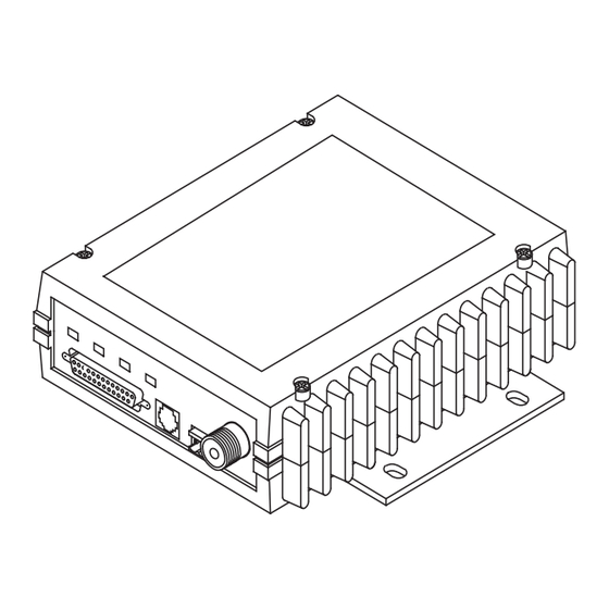
TOT [1-255, ON, OFF] 3.2 Transceiver Mounting This command sets or displays the transmitter Time-out Timer value Figure 6 shows the mounting dimensions of the transceiver. (1–255 seconds), as well as the timer status ( ). If the timer is on, and the radio remains keyed for a longer duration than the value, Invisible place holder... -
Page 20: Feedlines
Invisible place holder SHOW [DC, PORT, PWR] command displays different types of information based on SHOW the command variables. The different parameters are: • —Display DC input/output voltages • —Display the connector port (RJ-11 or DB-25) that is active PORT for diagnostics and control. -
Page 21: Rssi
RSSI 3.5 Data Interface Connections This command continuously displays the radio’s Received Signal The transceiver’s connector is used to connect the DATA INTERFACE Strength Indication (RSSI) in dBm units, until you press the Enter key. transceiver to an external DTE data terminal that supports the EIA-232 Incoming signal strengths from –50 dBm to –120 dBm can be read. -
Page 22: Stat
Table 4. DATA INTERFACE Connector Pinouts This command activates the transmitter. See also the command. DKEY Input/ MODEL Number Output Pin Description Protective Ground. Connects to ground (negative supply This command displays the radio’s model number code. potential) on the radio’s PC board and chassis. TXD—Transmitted Data. -
Page 23: Operation
DUMP Table 4. DATA INTERFACE Connector Pinouts (Continued) This command displays all the programmed settings of the radio. The Input/ Number Output Pin Description HHT display is too small to list all the command settings at one time. Therefore, this command is most useful if the command is issued from 9.9 Vdc Regulated Output. -
Page 24: Led Indicators
4.1 LED Indicators The default selection is . In this mode, CTS will go high following RTS, subject to the CTS programmable delay time. If the com- DATAKEY Table 5 describes the function of each status LED. mand is set to , keying can be stimulated by the input of characters at the data port. -
Page 25: Applications
5.0 TRANSCEIVER PROGRAMMING If data buffering is , the radio operates in seamless mode. Data bytes will be sent over the air as quickly as possible, but the receiver buffers (stores) the data until enough bytes have arrived to cover worst-case Programming and control of the transceiver is performed through the radio’s RJ-11 (Diagnostics) connector with an MDS Hand-Held... -
Page 26: Hand-Held Terminal Setup
Invisible place holder Each bit that is a ‘1’ identifies an associated alarm condition that can trigger the alarm output status line. Each bit that is a ‘0’ treats the asso- ciated alarm as irrelevant when deciding whether or not to assert the alarm output status line. -
Page 27: Description
Table 7. Command summary (Continued) 3. Set up the HHT as listed in Table Table 6. HHT Operational Settings Command name Function TEMP Display the internal temperature of the radio in Parameter Setting Parameter Setting degrees Celsius. Details page 29 Re-init HT Scroll On 33rd... -
Page 28: Asense [Hi/Lo]
—The command was unable to successfully complete. Table 7. Command summary (Continued) COMMAND FAILED This may indicate an internal software problem. Command name Function DTYPE [NODE/ROOT] (Diagnostics) Sets up a radio as a Root or Node —Software was unable to program the internal radio NOT PROGRAMMED radio.
Need help?
Do you have a question about the MDS 1710 A and is the answer not in the manual?
Questions and answers