Table of Contents
Advertisement
Advertisement
Table of Contents

Related Manuals for Radiodetection RD400PDL-2


Summary of Contents for Radiodetection RD400PDL-2
- Page 1 RD400PDL-2/PXL-2 User Guide Revision 0 - 04.97...
- Page 2 This section details where to find and how to use the various operating controls and features, etc., relevant to the RD400PDL-2/PXL-2 receivers. As there are several RD400PDL-2/PXL-2 variants, some of the features described in the Receivers section may not be available. Refer to the product label for features available.
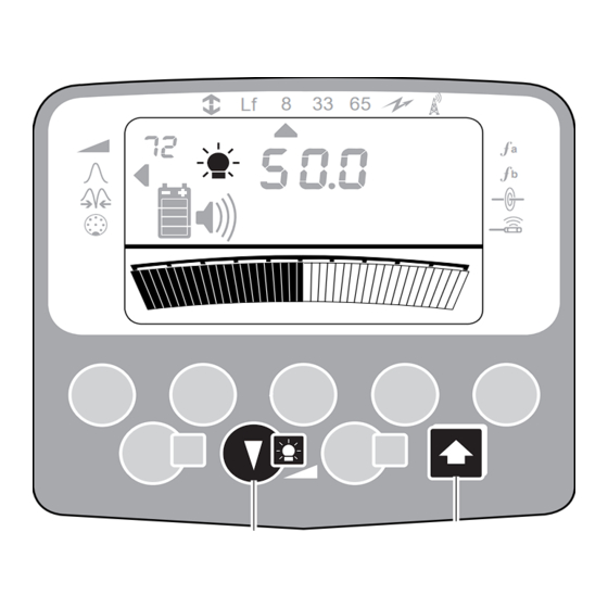
- Page 3 RD400PDL-2/PXL-2 User Guide Precision Locators On/Off (1) 33 65 One press for On, further press for Off. If after 5 minutes no control key has been pressed, there is an audible warning followed by auto switch Off. Batteries (2) 33 65 Display provides 4 segment continuous indication of battery status.
- Page 4 RD400PDL-2/PXL-2 User Guide Precision Locators Frequency/Mode (5) 33 65 Moves the mode pointer through choice of modes available from those indicated along top of display and custom frequencies (fa/fb) on the right. Selects Power or Radio (passive modes) and frequencies corresponding to Transmitter (active modes).
- Page 5 RD400PDL-2/PXL-2 User Guide Precision Locators Left/Right Indication (8) 33 65 Indicates direction to target line in Null mode when Receiver is used to locate with internal aerials or A-Frame, except in Power mode. 33 65 Gain Down/Up (9) Press either key (or operate touch gain control, if fitted) to increase or decrease Receiver gain.
- Page 6 RD400PDL-2/PXL-2 User Guide Precision Locators Depth (12) 33 65 Press to display depth from Receiver to target line/sonde when directly over line/sonde. Depth measurement may not be available in all modes on some PXL-2 models. Current (13) Press once to obtain current value (mA) of active target line signal when directly over line, except in Power or Radio modes.
- Page 7 RD400PDL-2/PXL-2 User Guide Locator Use Locate Switch Receiver On. Options and facilities available are indicated during display test. Check Receiver battery indicator shows at least one bar. If required, initiate a Self Test. Power Mode Some cables radiate power energy signals.
- Page 8 RD400PDL-2/PXL-2 User Guide Locator Use When a signal is detected continue along search route until signal strength reduces, returning to position where signal is strongest. Pinpoint Rotate Receiver through 90° until minimum signal is detected. Receiver blade is now in line with target line.
- Page 9 RD400PDL-2/PXL-2 User Guide Locator Use Mark target line position with chalk or paint. Continue sweeping the area, following grid pattern. Null Select Null mode. Walk along path of target line. Minimum response with an increased response each side indicates position of target line.
- Page 10 Using Frequency/Mode key select CD mode, hold Receiver over target line close to, and with back to, Transmitter. CD - Reset (RD400PDL-2 only) Before using Current Direction information a CD 8 33 65 reset must be carried out. (Refer to the appropriate Receiver section).
- Page 11 RD400PDL-2/PXL-2 User Guide Locator Use CD - Read (RD400PDL-2 only) The current direction of a line can be verified by using conductors to which the signal has coupled such as a railway line, a continuous metal fence or a highway crash barrier.
- Page 12 RD400PDL-2/PXL-2 User Guide FaultFinding RD Accessory A-Frame The Accessory A-Frame is can be used to find cable faults to ground in two ways, the CD signal method and FF signal method. Transmitter Setup The only method of Transmitter signal application that can be used for fault finding is by direct connection to the defective cable or to the sheath.
- Page 13 RD400PDL-2/PXL-2 User Guide FaultFinding Press the A-V-O key to display current (mA). Press the Up or Down keys to set the required output current level (typically 20 mA). In situations FF Normal where there is a high degree of interference...
- Page 14 RD400PDL-2/PXL-2 User Guide FaultFinding Pressing the Peak/Null key selects either Peak, Null (standard locate modes) or the Accessory 8 33 65 Socket when A-Frame is connected. Use the Receiver in the Peak or Null mode to locate the cable. Using the Peak/Null key, select the Accessory...
- Page 15 RD400PDL-2/PXL-2 User Guide FaultFinding Connect the A-Frame to the Receiver Accessory 33 65 Socket. Switch the Receiver On and select 8 kHz using the 'f' key. Using the Peak/Null key, select Peak or Null and trace the route of the suspect section of cable.
- Page 16 RD400PDL-2/PXL-2 User Guide FaultFinding Rotate the A-Frame through 90° and FaultFind along the marked line, until the exact point is found where the arrow changes direction. The centre line of the A-Frame is now directly over the fault. Difficult Ground Conditions...
- Page 17 RD400PDL-2/PXL-2 User Guide EMS Marker Location The RD400PXL-2 EMS Receiver is designed to locate buried conductors and 3M markers either simultaneously or independently. Marker location is achieved by the operator fitting an 'EMS Boot' to the Receiver. Fitting/Removing the EMS Boot...
- Page 18 RD400PDL-2/PXL-2 User Guide EMS Marker Location Buried Conductor and Marker Locate The receiver can now be used to locate a buried conductor and a Marker simultaneously. The Left/Right arrows [7] indicate the buried conductor position while the bargraph [8] and numeric display indicate the amplitude of the received Marker signal.
- Page 19 RD400PDL-2/PXL-2 User Guide RD433HCTX-2 Transmitter On/Off (1) RD433HCTx-2 Turns the Transmitter On and Off. FF Normal Arrows on the main label indicate the required FF Boost Multi transmitter alignment for signal induction. Connect 24V User Hz Connect 50V Batteries (2)
- Page 20 RD400PDL-2/PXL-2 User Guide RD433HCTX-2 Transmitter When Multi is selected, any combination of Lf, 8k, 33k and 65k can be transmitted using Direct Connection. The selection procedure is as follows: Using the Mode/Select keys select Multi. A FF Normal flashing flag will appear next to Lf.
- Page 21 RD400PDL-2/PXL-2 User Guide RD433HCTX-2 Transmitter Speaker (9) Press to adjust speaker level (Low, High or Off). k Ω Hz FF Normal FF Boost Backlight (10) Multi Connect 24V Turns Backlight On and Off. User Hz Connect 50V Radiodetection Radiodetection Ltd.
- Page 22 RD400PDL-2/PXL-2 User Guide RD433HCTX-2 Transmitter Connection Cable Red cable connects the Transmitter signal directly to a target line. Black cable provides the ground return via Ground Stake. black earth Ground Stake Ground Stake is for making a ground connection live to provide a return signal.
- Page 23 RD400PDL-2/PXL-2 User Guide RD433HCTX-2 Transmitter On/Off (1) First press turns Transmitter On and selects first frequency (not available in Induction mode). Second press selects second frequency. Third press selects third frequency. RD400LCTx 01/LX1337L1INT/0 Fourth press turns Transmitter Off. LEDs indicate which frequency has been selected.
- Page 24 RD400PDL-2/PXL-2 User Guide RD433HCTX-2 Transmitter Connection Cable Red cable connects the Transmitter signal directly to target line. Black cable provides the ground return via Ground Stake. Black Ground Stake Ground Stake is for making a ground connection to provide a return signal.
- Page 25 RD400PDL-2/PXL-2 User Guide Transmitter Use Induction The Transmitter has an internal aerial that will induce a signal onto a line (or lines) directly below it, without the need for access to the line. Generally, induction can only be used to depths of 2 m (6 ft).
- Page 26 RD400PDL-2/PXL-2 User Guide RD433HCTX-2 Transmitter A good connection is indicated by a change in loudspeaker tone. If there is no tone change, check the electrical contact and ground. If necessary change the position of the ground or tip water over the ground contact if placed in dry soil or sand.
- Page 27 RD400PDL-2/PXL-2 User Guide Transmitter Use Live Plug Connector Applies the Transmitter signal to a live domestic power socket and via the domestic wiring system onto the service cable and the supply cable in the street. The signal should be detectable on the supply system to a few hundred paces each side of the point of application.
- Page 28 Bristol BS14 OAZ, UK Bridgton, Maine 04009,USA Tel: +44 (0) 117 976 7776 Tel: (207) 647-9495 Fax: +44 (0) 117 976 7775 Radiodetection products are under continuous development and Toll Free: 877-247-3797 are subject to change without notice email:sales.uk@radiodetection.spx.com Fax: (207) 647-9496 http://www.radiodetection.com...
Need help?
Do you have a question about the RD400PDL-2 and is the answer not in the manual?
Questions and answers