
Related Manuals for Radiodetection 1205CXB


Summary of Contents for Radiodetection 1205CXB
- Page 1 1205CXB ™ High Resolution TDR Cable Fault Locator Operation manual 90/1205CXB-OPMAN-ENG/01...
- Page 2 1205CXB OPERATION MANUAL v1 Inside front cover © Copyright Radiodetection Ltd 2022...
-
Page 3: Preface
1205CXB. Radiodetection products, including this manual, are under continuous development. The information contained within is accurate at time of publication; however the 1205CXB, this manual and all its contents are subject to change. -
Page 4: Table Of Contents
1205CXB OPERATION MANUAL v1 Contents Preface ................................3 Before you begin ............................3 Safety ................................ 3 Introduction ..............................6 Description and Overview ......................... 6 Velocity of Propagation (VOP) ........................6 Typical VOPs for some common cable types ..................6 VOP and V/2 ............................8 System Overview ............................ - Page 5 1205CXB OPERATION MANUAL v1 Cable joint ............................18 Wet splice or joint ..........................18 Bridge tap ............................19 Water ingress ............................19 Load coil .............................. 19 Return Loss ..............................20 Reflection Coefficient and VSWR ......................21 WaveView™ PC software ..........................22 Ordering Information ..........................
-
Page 6: Introduction
Introduction Description and Overview The 1205CXB™ is a High Resolution Cable Fault Locator, also known as a Cable Radar or a Time Domain Reflectometer (TDR). The 1205CXB transmits electrical pulses into a cable, and a portion of the pulse energy reflects back from cable imperfections. These can be discontinuities (eg cable joints, changes in cable type or the far end of the cable under test) or faults (typically short circuits, open circuits, water ingress or corroded connections). - Page 7 1205CXB OPERATION MANUAL v1 The VOP and characteristic impedance values for some common cable types are: Use/Type Cable type Data Ethernet 0.77 RG58 0.78 RG58/U 0.76 Thicknet 0.77 Thinnet 0.68 Twisted pair 0.66 U/UTP cat 5e, 6 0.67 UTP26 0.64 Phone Gel 0.912...
-
Page 8: Vop And V/2
1205CXB OPERATION MANUAL v1 VOP and V/2 Some users like to use V/2 as an alternative to VOP. V/2 is the speed of the pulse in a cable, in m/µs, halved. There is a direct relationship between VOP and V/2 as shown in the following tables. -
Page 9: System Overview
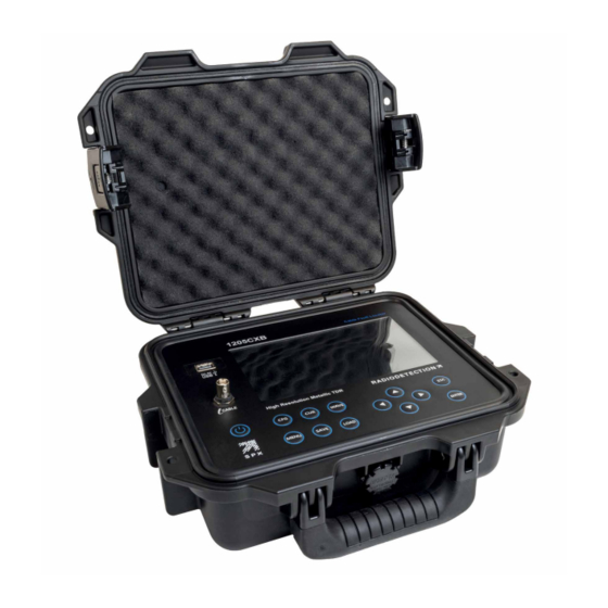
USB port BNC cable connector Display Keypad Button Name Function Power Turn 1205CXB On and Off Select parameters and auto search in the ConFiGuration ConFiG submenu CURsor Select cursor 1 or 2 Select move or zoom function for a WAVEform waveform ©... -
Page 10: Display
1205CXB OPERATION MANUAL v1 Select units, a pre-loaded cable and MENU system settings Save waveform to 1205CXB’s memory or SAVE Load a waveform from 1205CXB’s LOAD memory or USB Increase/decrease parameters Left, up, down, right arrows Zoom, move waveforms and cursors... -
Page 11: Navigating The Config, Cursor And Waveform Submenus
Launch and reflected pulses The display of the 1205CXB shows a launch pulse at the left hand side of the display and a reflected pulse if any cable imperfections are within range (see “Description” section). When cursor 2 is positioned at the start of the reflected pulse and the VOP is set correctly, the distance to the imperfection is displayed in the top right hand corner of the display. -
Page 12: Basic Operation
1205CXB OPERATION MANUAL v1 Basic operation 1. Charge the 1205CXB using the mains charger and cable supplied, via the USB-A port 2. Press the Power button for 2 seconds to power the 1205CXB on 3. Attach the cable for analysis to the BNC connector, either directly or using one of the connection cables supplied 4. -
Page 13: Menu
Many Set the 1205CXB up with an industry standard cable's settings Auto search on On, Off Set the 1205CXB to search your cable for boot analysis immediately on power up Live signal check On, Off Set the 1205CXB to check for live voltages... -
Page 14: Save And Load Waveforms
1205CXB OPERATION MANUAL v1 Save and Load waveforms The 1205CXB allows you to save waveforms and to recall them. You can display recalled waveforms together with live cable waveforms to compare them easily. This can be very useful in cases such as comparing a waveform taken when a cable was installed with a live one when a customer reports a fault. -
Page 15: Displaying Loaded Waveforms
When a loaded waveform is displayed, the 1205CXB also shows its save information at the top right hand side of the display: ... -
Page 16: Cable Analysis
The left and right arrow buttons change the VOP by 1%. The up and down arrows change the VOP by 0.1%. Out Z Match the output impedance of the 1205CXB to the cable for improved signal transfer Thres Threshold is the minimum voltage range over which the 1205CXB detects an event. This... -
Page 17: Waveform Menu Details
1205CXB OPERATION MANUAL v1 Waveform menu details Pressing the button (Button 7) more than once toggles between Zoom and Move. In Zoom mode: using the up and down arrow keys changes the zoom in the Y axis using the left and right arrow keys changes the zoom in the X axis In Move mode: ... -
Page 18: Typical Waveforms
1205CXB OPERATION MANUAL v1 Typical waveforms You will encounter a variety of waveforms during testing because there is a huge number of different cable types electrical and environmental conditions can change and affect TDR test results, and ... -
Page 19: Bridge Tap
1205CXB OPERATION MANUAL v1 Bridge tap Water ingress Bridge Water ingress 503.3ft 213.5ft A bridged tap will appear as a downward or negative This cable system has water ingress starting at 213.5ft reflection, because the impedance reduces at the from the beginning of the cable. The waveform of the... -
Page 20: Return Loss
1205CXB OPERATION MANUAL v1 Return Loss The 1205CXB provides you with a numerical measurement of the severity of a fault. This is called the Return Loss and it is measured in dB. Return Loss is a ratio of the amplitudes of the reflected pulse and the transmitted pulse. It is calculated... -
Page 21: Reflection Coefficient And Vswr
1205CXB OPERATION MANUAL v1 Reflection Coefficient and VSWR Users sometimes use alternative measures to show the severity of a fault, including Reflection Coefficient and Voltage Standing Wave Ratio (VSWR). There are direct relations between dBRL and these as shown in the following table and graphs:... -
Page 22: Waveview™ Pc Software
1205CXB OPERATION MANUAL v1 WaveView™ PC software Radiodetection’s WaveView™ software allows you to view, analyse and interpret 1205CXB waveforms on your computer. You can pan and zoom easily for looking at the signals in-depth. WaveView also lets you add notes and make corrections, such as to the VOP, made in the on-site evaluation. -
Page 23: Ordering Information
1205CXB OPERATION MANUAL v1 Ordering Information Description Sales Part Number Notes 1205CXB Cable Analyzer TDR 10/1205CXB Cable analyzer BNC-to-BNC connection cable Contact Radiodetection Standard accessory BNC-to-Alligator clip connection cable Contact Radiodetection Standard accessory BNC-to-F-type adapter Contact Radiodetection Standard accessory Multi-regional USBA charger... -
Page 24: Additional Information
Service The 1205CXB TDR contains no user serviceable items. In the unlikely event of failure, please contact your local representative for details of repair or replacement. In order to maintain the accuracy of this equipment, Radiodetection recommend that you perform an annual calibration and maintenance. -
Page 25: Compliance
1205CXB OPERATION MANUAL v1 Compliance This equipment has been certified to the following Standards / Regulations: Product Standards EU (CE mark) GB/NI (UKCA mark) USA (FCC) Canada (IC) EN 61326-1:2013 Electromagnetic Electromagnetic EN 55011:2009/A1:2020 compatibility (EMC) Compatibility EN 61000-3-2:2014 Directive (2014/30/EU) -
Page 26: Warranty
Before a unit is submitted for service or repair, under the terms of this warranty or otherwise, any data stored on the unit should be backed-up to avoid any risk of data loss. Radiodetection will not be responsible for loss or erasure of data storage media or accessories. - Page 27 Use of the product with accessories, peripheral equipment and other products of a type, condition and standard other than prescribed by Radiodetection. viii. Repair or attempted repair by persons who are not Radiodetection warranted and certified repair houses. Adjustments or adaptations without Radiodetection’s prior written consent, including...
- Page 28 Copyright © 2022 Radiodetection Ltd. All rights reserved. Radiodetection is a subsidiary of SPX Corporation. Radiodetection and 1205CXB are registered trademarks of Radiodetection in the United States and/or other countries. Trademarks and Notices. Due to a policy of continued development, we reserve the right to alter or amend any published specification without notice. This document may not be copied, reproduced, transmitted, modified or used, in whole or in part, without the prior written consent of Radiodetection Ltd.
Need help?
Do you have a question about the 1205CXB and is the answer not in the manual?
Questions and answers