Table of Contents
Advertisement
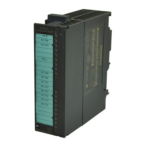
SIMATIC
SM 335 – High-Speed
Analog Input/Output Module for
the SIMATIC S7-300
Manual
08/2004 Edition
6ES7 335-7HG00-8BA1
Preface, Contents
Characteristics and Technical
Specifications of the SM 335
Connecting the Inputs and
Outputs of the SM 335
Data Exchange with the SM 335
Interval Counter Input
Special SM 335 Operating Modes
Detecting and Correcting Faults
List of Abbreviations
Index
1
2
3
4
5
6
A
Advertisement
Chapters
Table of Contents

Related Manuals for Siemens SIMATIC SM 335


Summary of Contents for Siemens SIMATIC SM 335
- Page 1 Preface, Contents Characteristics and Technical Specifications of the SM 335 SIMATIC Connecting the Inputs and Outputs of the SM 335 SM 335 – High-Speed Data Exchange with the SM 335 Analog Input/Output Module for the SIMATIC S7-300 Interval Counter Input Special SM 335 Operating Modes Manual Detecting and Correcting Faults...
-
Page 2: Contents
Siemens. The product will function correctly and safely only if it is transported, stored, set up, and installed as intended, and operated and maintained with care. -
Page 3: The Simatic S7
Preface Important In order to obtain SIMATIC interference immunity, the SM 335 module must always be operated with an interference suppression filter (see Section 2.6). Content of this manual This manual describes the function of the SM 335 analog input/output module; AI4/AO4 x 14/12 bits. - Page 4 Preface Preface Scope of the documentation package You can order the documentation for the SM 335 separately from the module. The order number for the manual appears in the table below: Documentation Order Number • SM 335 - High-Speed Analog Input/Output 6ES7 335-7HG00-8BA1 Module for the SIMATIC S7-300 Other references...
- Page 5 Preface Preface C-Tick-Mark The S7-300 programmable controller meets the requirements of the AS/NZS 2064 standard (Australia and New Zealand). Standards The S7-300 programmable controller meets the requirements and criteria of the IEC 61131-2 standard (Programmable Controllers, Part 2: Equipment Require- ments and Tests).
-
Page 6: Specifications Of The Sm
Communication with SIMATIC PG/OP, configuration in STEP 7. Additional Support Please contact your local Siemens representative if you have any queries about the product described in this manual, which are not answered here. http://www.ad.siemens.com/automation/partner SM 335 – High-Speed Analog Input/Output Module for the SIMATIC S7-300... - Page 7 Technical Support Local time: 24 hours a day, 365 days a year Phone: +49 (180) 5050-222 Fax: +49 (180) 5050-223 E-mail: adsupport@ siemens.com GMT: +1:00 Europe/Africa (Nuremberg) United States (Johnson City) Asia/Australia (Beijing) Authorization Technical Support and Technical Support and Authorization...
- Page 8 Queries If you have any queries about the S7-300 programmable controller, please contact your local Siemens representative. In case you have any questions or suggestions concerning this manual, please fill in the correction sheet and return it to us. The correction sheet can be found at the end of the manual.
-
Page 9: Table Of Contents
Contents Characteristics and Technical Specifications of the SM 335 ....Characteristics features of the SM 335 ......Terminal connection diagram for the SM 335 . - Page 10 Contents Contents Evaluating SM 335 diagnostics ........3-29 3.4.1 Hardware interrupt...
-
Page 11: Characteristics And Technical Specifications Of The Sm 335
Characteristics and Technical Specifications of the SM 335 SIMATIC S7-300 The SM 335 is an input/output module (signal module) for the SIMATIC S7-300. The SM 335 has the same general technical specifications as all signal modules of the SIMATIC S7-300. Order number Order the SM 335 under the following order number: 6ES7 335-7HG01-0AB0... -
Page 12: Characteristics Features Of The Sm 335
Characteristics and Technical Specifications of the SM 335 Characteristics features of the SM 335 Characteristic features The SM 335; AI4/AO4 14/12 bit has the following characteristic features: Analog inputs: • Four isolated analog inputs • Integrated 10 V/25 mA sensor power supply •... -
Page 13: Terminal Connection Diagram For The Sm 335
Characteristics and Technical Specifications of the SM 335 Terminal connection diagram for the SM 335 Terminal connection diagram Figure 1-1 shows the terminal connections for the SM 335 analog input/output module. Analog inputs: Analog outputs: Voltage/ Voltage output Fault LEDs – red current measurement 24 V 24 V... - Page 14 Characteristics and Technical Specifications of the SM 335 Revision Level Products with the same number can be distinguished by the revision level. The revision level is incremented by upwardly-compatible function expansions or fault corrections. The revision level of the module is identified by “X” (see Figure 1-1); in this case the revision level is 1.
-
Page 15: Block Diagram Of The Sm 335
Characteristics and Technical Specifications of the SM 335 Block diagram of the SM 335 Block diagram Figure 1-2 shows the block diagram of the SM 335. You will find detailed technical specifications for the SM 335 on the following pages. Internal power supply 24 V Analog outputs... -
Page 16: Setting The Measuring Range With The Measuring Range Module
Characteristics and Technical Specifications of the SM 335 Setting the measuring range with the measuring range module Measuring range module A measuring range module is located on the left of the input/output module. The measuring range module is used to set the method of measuring on the analog inputs, that is, to choose between voltage and current measuring. -
Page 17: Technical Specifications For The Sm 335
Characteristics and Technical Specifications of the SM 335 Technical specifications for the SM 335 1.5.1 General technical specifications Table 1-2 General technical specifications Dimensions and weight Dimensions W x H x D (mm) 40 x 125 x 120 Weight Approx. 300 g Module-specific data Number of inputs Number of outputs... -
Page 18: Technical Specifications For The Analog Inputs
Characteristics and Technical Specifications of the SM 335 1.5.2 Technical specifications for the analog inputs Table 1-3 Technical specifications for the analog inputs Noise suppression and error limits for the inputs Suppression of noise voltage for f = n x (f1"1%), (f1 = interference frequency) •... - Page 19 Characteristics and Technical Specifications of the SM 335 Table 1-3 Technical specifications for the analog inputs Analog value formation for the outputs Measuring principle Successive approximation Conversion time (per channel) in ms Max. 200 • Basic conversion time for 4 channels in ms Max.
-
Page 20: Technical Specifications For The Analog Outputs
Characteristics and Technical Specifications of the SM 335 1.5.3 Technical specifications for the analog outputs Table 1-4 Technical specifications for the analog outputs Analog value formation for the outputs Resolution (incl. overrange) • " 10 V 11 bits + sign •... -
Page 21: Technical Specifications For The Interval Counter
Characteristics and Technical Specifications of the SM 335 1.5.4 Technical specifications for the interval counter Table 1-5 Technical specifications for the interval counter Interval-counter-specific data Number of inputs Cable length shielded 200 m Voltages, currents, potentials Rated load voltage L+ 24 V DC •... - Page 22 Characteristics and Technical Specifications of the SM 335 Table 1-5 Technical specifications for the interval counter Sensor selection data " 30 V Permissible input voltage (destruction limit) Permissible input current for interval input (destruction 5 mA limit) Minimum permissible pulse widths at the counter input •...
-
Page 23: Sm 335 Operating Modes
Characteristics and Technical Specifications of the SM 335 SM 335 operating modes Operating modes The SM 335 can operate in the following modes: • Free cycle (corresponds to HW Config setting for SM 335: 0.5 ms cycle time) • Conditional cycle (corresponds to HW Config setting for SM 335: 1 to 16 ms cycle time) Special operating modes In addition, the SM 335 can be switched to the following modes for a brief period of... - Page 24 Characteristics and Technical Specifications of the SM 335 Figure 1-3 shows the various components of the cycle time for a free cycle. Conversion time for analog input channel CH3 Conversion time for analog input channel CH2 Conversion time for analog input channel CH1 Conversion time for analog input channel CH0...
- Page 25 Characteristics and Technical Specifications of the SM 335 The SM 335 only updates the relevant analog output channel when modifications are made to the output value. • Four activated input channels and four activated output channels with the re- quired output, which is dependent on constantly changing values, yields a cycle time of 1200 µs (200 µs + 4 x 200 µs + 4 x 50 µs).
-
Page 26: Conditional Cycle Mode
Characteristics and Technical Specifications of the SM 335 1.6.2 Conditional Cycle mode Conditional Cycle In the conditional cycle operating mode, you can define the cycle time. Follo- wing conversion of all analog inputs, the SM 335 can generate an end-of-cycle in- terrupt to the CPU (see Subsection 3.4.1 Hardware Interrupt). -
Page 27: Connecting The Inputs And Outputs Of The Sm 335
Connecting the Inputs and Outputs of the SM 335 Assembly Before connecting the SM 335, you must first assemble the SM 335. The SM 335 is assembled in the same way as all other SIMATIC S7-300 I/O modules. Please read the SIMATIC S7-300 Hardware and Installation Manual. SIMATIC S7-300 When connecting the SM 335, please note the installation guidelines in the SIMATIC S7-300 Hardware and Installation Manual. -
Page 28: Connecting The Inputs And Outputs Of The Sm 335
Connecting the Inputs and Outputs of the SM 335 Basic information about connecting the SM 335 Connecting the analog inputs and outputs You can find detailed information about connecting the analog inputs and outputs in the SIMATIC Programmable Logic Controller, S7-300 Module Data Reference Ma- nual. -
Page 29: Connecting The Analog Inputs
Connecting the Inputs and Outputs of the SM 335 Connecting the analog inputs Recommendation The high conversion speed of the SM 335 means that the interference produced can have a negative effect on the measurement input voltages in particular. The configuration described below is in general the configuration, which is least susceptible to interference. - Page 30 Connecting the Inputs and Outputs of the SM 335 Non-Isolated In contrast to other applications (e. g., when connecting thermocouples), you should ground the sensors’ analog zero potential in the vicinity of the SM 335. The easiest way to do so is to connect pins 10, 12, 14 and 16 with analog zero potential (PIN 6) and connect M in the vicinity of the module in the rack with the central grounding point (CGP) of the module.
-
Page 31: Connecting The Analog Outputs
Connecting the Inputs and Outputs of the SM 335 Connecting the analog outputs Connecting the analog outputs The analog outputs must be connected as voltage outputs. Detailed informa- tion can be found in the SIMATIC Programmable Logic Controller, S7-300 Module Data Reference Manual. -
Page 32: Connecting The Interval Counter Input
Connecting the Inputs and Outputs of the SM 335 Unused analog outputs To ensure that unused analog outputs on the SM 335 are dead, you must deacti- vate them and leave them open. An analog output is deactivated with HW Config. Connecting the interval counter input Non-Isolated If you wire the interval counter input as a non-isolated input, connect pin 19 (M... -
Page 33: Connecting The Sensor Power Supply
Connecting the Inputs and Outputs of the SM 335 Connecting the sensor power supply Purpose The sensor power supply is designed for resistance-type sensors (e. g., linear po- tentiometers). Connections Figure 2-3 shows an example of how to connect the sensor power supply. SM 335 10 V É... - Page 34 Connecting the Inputs and Outputs of the SM 335 Cable There is a voltage drop on the cable between SM 335 and the linear potentiometer. Because of the SM 335’s high resolution, this can play a role in the measuring of the analog signal.
-
Page 35: Correcting The Sensor Power Supply
Connecting the Inputs and Outputs of the SM 335 2.5.1 Correcting the sensor power supply Purpose The power supply for the sensors is a 10 V output voltage. This voltage may devi- ate slightly from 10 V. The deviation results from the tolerances of the components used on the SM 335. -
Page 36: Interference Suppression Filter For 24 V Supply Voltage
Connecting the Inputs and Outputs of the SM 335 Interference suppression filter for 24 V supply voltage Caution The SM 335 module must always be used with an interference suppression filter to obtain interference immunity for SIMATIC. Interference Interference may reach the SM 335 via the 24 V voltage supply. One cause of such interference is the switching of loads connected to the 24 V circuit. - Page 37 The interference suppression filter can be obtained by quoting order number: 6ES7 335-7HG00-6AA0 Type: e. g., EPCOS SIFI C, order reference B84113-C-B30 Please contact your local Siemens representative for more information. SM 335 – High-Speed Analog Input/Output Module for the SIMATIC S7-300 2-11...
- Page 38 Connecting the Inputs and Outputs of the SM 335 SM 335 – High-Speed Analog Input/Output Module for the SIMATIC S7-300 2-12 6ES7 335-7HG00-8BA1...
-
Page 39: Data Exchange With The Sm 335
Data Exchange with the SM 335 Preliminary remark Data exchange with the SM 335 is defined here as follows: • Transfer of data to the SM 335 from the CPU and • Reading of data from the SM 335 by the CPU. Overview In this chapter, we have summarized all the data that can be transferred to the SM 335 or supplied by the SM 335. - Page 40 Data Exchange with the SM 335 In this chapter We deal with the following topics in this chapter: Topic Section Access via the I/O addresses Setting parameters via HW Config Modifying SM 335 parameters with the help of system func- tion 55 Evaluating SM 335 diagnostics SM 335 –...
-
Page 41: Access Via The I/O Addresses
Data Exchange with the SM 335 Access via the I/O addresses Principle You can access the SM 335 via I/O addresses. Input values Input values are values supplied by the SM 335. The input values contain measu- red values of the SM 335. You can load the input values via L PIB (or L PIW or L PID) operation. - Page 42 Data Exchange with the SM 335 Configuration The input values are located in bytes ModAdd (module start address) to Mo- dAdd + 15. See the SIMATIC Programmable Logic Controller, S7-300 Module Data Reference Manual for information about how to compute the module start address. Table 3-1 lists the input values, their addresses, and their default values.
- Page 43 Data Exchange with the SM 335 Number of end-of-cycle interrupts (ModAdd + 8) A user program can be synchronized via OB 40 using the end-of-cycle interrupt. Fast processing of the user program is also possible via the interrupt (e. g., for ad- justment routines).
- Page 44 Data Exchange with the SM 335 Table 3-2 Meaning of the bits in the SM 335 return code Description = 1: SM 335 is in “Measuring Only” or “Comparator” mode = 0: SM 335 is in “Conditional Cycle” or “Free Cycle” mode = 1: “Measuring Only”...
-
Page 45: Output Values
Data Exchange with the SM 335 3.1.2 Output values Principle The analog output values converted into binary in the CPU can be transferred to the SM 335 e. g., with the command “T PQW”. The SM 335 converts the binary form of the analog output signals into analog sig- nals and forwards them to the relevant outputs. -
Page 46: Analog Value Representation For Analog Input Channels
Data Exchange with the SM 335 3.1.3 Analog value representation for analog input channels The tables contain representations of the measuring values of individual measuring ranges of the analog inputs. Table 3-5 Analog Value Representation in the Bipolar Input Ranges Measuring Range Units Range... - Page 47 Data Exchange with the SM 335 Table 3-6 Analog Value Representation in the Unipolar Input Ranges Measuring Range Units Range 0 – 2 V 0 –10 V 0 – 20 mA 4 – 20 mA decimal hexa- decimal 2.370 V 11.852 V 23.70 mA 22.96 mA...
-
Page 48: Analog Value Representation For Analog Output Channels
Data Exchange with the SM 335 3.1.4 Analog value representation for analog output channels The table contains the analog value representation of the SM 335’s output chan- nels. 12 bits (+VZ) of the output value are converted in the 0-10 Volt range. Bit 0, Bit 1 and Bit 2 are not converted. -
Page 49: Setting Parameters Via Hw Config
Data Exchange with the SM 335 Setting parameters via HW Config Measuring Range Module You must plug in the measuring range module into the side of the SM 335. You can learn how to do this in Reference Manual SIMATIC Programmable Logic Controller, S7-300 Module Data. -
Page 50: Sm 335 Default Settings
Data Exchange with the SM 335 3.2.1 SM 335 default settings Default settings The analog input/output module has default settings. These default settings are used when no parameters are set using the STEP 7 “HW Config” tool. The defaults are listed in table 3-8. Table 3-8 SM 335 Default Settings Parameters... -
Page 51: Sm 335 Parameters Assignable With Hw Config
Data Exchange with the SM 335 3.2.2 SM 335 parameters assignable with HW Config Parameter assignment application The STEP 7 tool used to initialize the analog modules in a STEP 7 environment is called “HW Config”. SM 335 parameters Table 3-9 provides an overview of the SM 335 parameters which can be assigned with HW Config. - Page 52 Data Exchange with the SM 335 Table 3-9 SM 335 parameters in HW Config Parameters Parameters SM 335 Value Range Default Output • Method Deactivated / Voltage Voltage • Range from – 10 V to + 10 V from 0 V to + 10 V The setting 0.5 ms in HW Config means: Free Cycle The setting 1 to 16 ms in HW Config means: Conditional Cycle End-of-cycle interrupt enable...
- Page 53 Data Exchange with the SM 335 Response with CPU-STOP When the CPU is at STOP or executing the startup routine, the SM 335 outputs the substitute value to the relevant analog output until a new value is specified. The SM 335 uses the following as a substitute value: •...
-
Page 54: Modifying Sm 335 Parameters With The Help Of System Function 55
Data Exchange with the SM 335 Modifying SM 335 parameters with the help of system function 55 HW Config In RUN mode of the CPU, you can modify some parameters (dynamic parameters) via system function 55. For other methods of modifying parameters: see Reference Manual System Soft- ware for S7-300/400 System and Standard Functions. -
Page 55: Sm 335 Static Parameters
Data Exchange with the SM 335 3.3.1 SM 335 static parameters The static parameters can only be modified via HW Config. Data Record 0 Data record 0 of the SM 335 contains static parameters (see Table 3-10) Table 3-10 SM 335 parameters in Data Record 0 Byte Content Default... -
Page 56: Sm 335 Parameters In The Free Cycle And Conditional Cycle Modes
Data Exchange with the SM 335 3.3.2 SM 335 parameters in the Free Cycle and Conditional Cycle Modes Data Record 1 (DR1) Data record 1 (DR1) of the SM 335 contains dynamic parameters (see Table 3-11). The parameters are set via HW Config, or can be modified via system function 55. Data record DR1 must always be completely transferred using system function 55. - Page 57 Data Exchange with the SM 335 Interrupt and substitute value output (DR1, Byte 0) The interrupt and substitute value output parameter defines the following: • Whether a hardware interrupt (conditional cycle only) is to be generated • Whether a diagnostics interrupt is to be generated •...
- Page 58 Data Exchange with the SM 335 Analog input measuring range (DR1, Byte 2-5) The default parameters for the analog input measuring range depend on the set- ting on the SM 335’s measuring range module. Table 3-12 Parameters for the analog input measuring range Measuring range Default parameters Permissible parameters...
- Page 59 Data Exchange with the SM 335 Measuring cycle time (DR1, Byte 10) The “measuring cycle time” parameter specifies the length of a measuring cycle. Permissible values are those from 01 to 00 The default value is 01 The value 01 specifies a free cycle, i.e., a measuring cycle has a duration of about 0.9 ms (if additional analog outputs are updated, 1 to 1.2 ms are required, depending on the number of analog outputs).
- Page 60 Data Exchange with the SM 335 Open-wire test (DR1, Byte 12) You use the open-wire test parameter (byte 12 in data record 1) to determine whe- ther an open-wire test is to be executed for the relevant analog input. 7 6 5 4 3 2 1 0 Analog input CH0 Analog input CH1 Analog input CH2...
-
Page 61: Sm 335 Parameter For "Comparator" Mode
Data Exchange with the SM 335 3.3.3 SM 335 parameter for “Comparator” mode In “Comparator” special mode, the SM 335 compares a specified analog value with the analog value measured on one of the analog inputs. The SM 335 behaves like a comparator in this operating mode. - Page 62 Data Exchange with the SM 335 Analog output value With Comparator 1 or 2, the SM 335 outputs the specified analog values on up to 3 analog outputs (see Section 5.2). Comparator time (DR1, Byte 10) During the time Comparator 2 is active, the SM 335 cannot generate a hardware interrupt for the end-of-cycle.
- Page 63 Data Exchange with the SM 335 Note For reasons of compatibility with older module versions, the SM 335 has two comparator modes. Comparator mode is set via bit 4: Bit 4 = 0: Mode 0 (comparator 1 and comparator 2 work on one measuring channel only;...
- Page 64 Data Exchange with the SM 335 Comparator 1 and Comparator 2 (DR1, bits 12.6 + 12.5) You switch Comparator 1 and 2 on with the Comparator 1 and 2 bits (see Table 3-14). Table 3-14 Checking the comparator with check bits 1 and 2 Bit 6 Bit 5 Behavior of the comparator...
-
Page 65: Sm 335 Parameters For "Measuring Only" Special Mode
Data Exchange with the SM 335 3.3.4 SM 335 parameters for “Measuring Only” special mode In “Measuring Only” special mode, the SM 335 only measures the analog inputs in Free Cycle and does not update the analog outputs. For detailed information about “Measuring Only”... -
Page 66: Fig
Data Exchange with the SM 335 Dynamic measuring cycle control Byte 11, “dynamic measuring cycle control”, has two tasks: • To switch on ‘Measuring Only’ mode • To disable/enable analog inputs Switching on the operating mode (DR1, Byte 11) To switch on “Measuring Only” mode, you must transfer all the SM 335 parameters and set bit 6 + 7 in byte 11: 7 6 5 4 3 2 1 0 “Comparator”... -
Page 67: Evaluating Sm 335 Diagnostics
Data Exchange with the SM 335 Evaluating SM 335 diagnostics Methods There are several methods of accessing SM 335 diagnostics: • With an enabled diagnostics interrupt via the local data in OB 82 • With a hardware interrupt via the local data of the interrupt OB (e. g., OB 40) •... -
Page 68: Hardware Interrupt
Data Exchange with the SM 335 3.4.1 Hardware interrupt OB 40 OB 40 is invoked when the SM 335 generates a hardware interrupt. Information about the cause of the hardware interrupt is entered in the local data section of OB 40. Local data The reasons for the SM 335 hardware interrupt are entered in byte 8 of the local data (see Figure 3-10). - Page 69 Data Exchange with the SM 335 Table 3-17 Interrupt triggered by comparator Byte Content Cause of hardware interrupt (see Figure 3-10) = 2#0000 0010 Comparator time [ms] The comparator time is set in byte 10 of the parameter assignment data re- cord DR1 (see Subsection 5.2.2).
-
Page 70: Format Of Diagnostic Data For The Sm 335
Data Exchange with the SM 335 3.4.2 Format of diagnostic data for the SM 335 Format Once diagnostic data record DR1 has been read by system function 59, the SM 335 diagnostic data are available in the specified memory. The diagnostic data are formatted as shown in Table 3-18. Table 3-18 SM 335 Diagnostic Data Module diag-... -
Page 71: Module Diagnostic Byte 1 (Byte 0)
Data Exchange with the SM 335 3.4.3 Module diagnostic byte 1 (byte 0) Format The SM 335 module diagnostic byte 1 contains group error information. Byte 1 has the format shown in Figure 3-11. 7 6 5 4 3 2 1 0 Group fault Internal fault External fault... - Page 72 Data Exchange with the SM 335 External fault Bit 2 is set in module diagnostic byte 1 when one of the following errors/faults oc- curs: • Measuring range module not connected • Measuring range module not connected correctly (default parameters do not match the measuring range module setting) •...
-
Page 73: Module Diagnostic Byte 2 (Byte 1)
Data Exchange with the SM 335 3.4.4 Module diagnostic byte 2 (byte 1) Content Module diagnostic byte 2 always contains the fixed value 35 3.4.5 Module diagnostic byte 3 (byte 2) Format Three different errors are flagged in Module Diagnostic Byte 3 (see Figure 3-12). -
Page 74: Module Diagnostic Byte 4 (Byte 3)
Data Exchange with the SM 335 3.4.6 Module diagnostic byte 4 (byte 3) Format Two different errors are flagged in module diagnostic byte 4 (see Figure 3-13). 7 6 5 4 3 2 1 0 EEPROM ADC/DAC fault Fig. 3-13 Module diagnostic byte 4 EEPROM fault Bit 2 is set in module diagnostic byte 4 when the SM 335 detects an internal error... -
Page 75: Channel-Specific Diagnostic Bytes (Bytes 4-15)
Data Exchange with the SM 335 3.4.7 Channel-specific diagnostic bytes (bytes 4-15) Channel type (byte 4) The SM 335 flags the type of channel in which the error occurred in byte 4 of the diagnostic data (00 : general error; 71 input;... - Page 76 Data Exchange with the SM 335 Common mode error (bytes 8-11, bit 1) There is an excessive common mode voltage at the analog input. If the common mode voltage is too high, the SM 335 simultaneously sets bit 2 in the module diag- nostic byte 1 to “1”...
-
Page 77: Interval Counter Input
Interval Counter Input Purpose With an interval counter, you can measure the number of intervals (continuous counter from 0 to 255) and the duration of an interval. You can use this data to calculate a speed, for example, if you know the path cov- ered during the interval. -
Page 78: Principle Of An Interval Counter
Interval Counter Input Principle of an interval counter Principle An interval counter counts the number of time intervals. Figure 4-1 shows a simple sensor. The sensor returns a ’1’ when light falls through one of the slots in the disc. When the disc rotates, the sensor returns the signal shown in the diagram. -
Page 79: Principles Of Measuring With The Interval Counter
Interval Counter Input Principles of measuring with the interval counter Purpose Pulses from a simple sensor are acquired via an interval counter input. The sensor might, for example, be located on the barrel extruder of an injection molding ma- chine. You can determine the rotational speed of the barrel from the interval bet- ween the 2 pulses. - Page 80 Interval Counter Input Upper limiting value The upper limiting value results from the condition that the interval between two positive edges must be at least 2.5 ms. The critical frequency is thus 400 Hz (equivalent to 24,000 revolutions per minute). At least 1 ms must be available for the high levels and the low level.
-
Page 81: Wiring The Interval Counter Input
Interval Counter Input Wiring the interval counter input Principle Figure 4-2 shows how to connect the interval counter input with a switch. The switch is actuated by a cam. The cam is on a rotating shaft, such as the barrel ex- truder of an injection molding machine. - Page 82 Interval Counter Input Cable A shielded, twisted-pair cable must be used. Connect the cable shield with the grounded rack via the shield connection in the same manner as all the other ana- log cables. Switch The switch and the cam must be such that the former remains closed for at least 1 ms and open for at least 1 ms at the highest attainable speed.
-
Page 83: Initializing The Sm 335'S Interval Counter Input
Interval Counter Input Initializing the SM 335’s interval counter input Parameter assignments The interval counter on the SM 335 requires no parameters. The pulse input func- tions independently of the parameters assigned to the remaining analog channels. The pulse input, therefore, does not have to be parameterized. The external counter can be retrospectively parameterized with a timeout. -
Page 84: Interval Counter Values
Interval Counter Input Interval counter values Address The values, which the SM 335 computes for the pulse input, are stored at the I/O address module start address + 12. Table 4-2 Pulse input values Module address Content + 12 Interval counter + 13 Interval duration, byte 1 + 14... -
Page 85: Example For Determining The Speed By Means Of The Interval Counter
Interval Counter Input Example for determining the speed by means of the in- terval counter Prerequisites It has been assumed that the SM 335 is in slot 4 and has module start address 256. The pulse counter input receives pulses from a sensor located on a barrel extruder. - Page 86 Interval Counter Input SM 335 – High-Speed Analog Input/Output Module for the SIMATIC S7-300 4-10 6ES7 335-7HG00-8BA1...
-
Page 87: Special Sm 335 Operating Modes
Special SM 335 Operating Modes Definition The SM 335 has two special operating modes: • “Comparator” mode and • “Measuring Only” mode Comparator In “Comparator” mode, the SM 335 compares an analog value with the analog va- lue measured at one of the analog inputs. The SM 335 behaves like a comparator in this mode. -
Page 88: Switching To The Special Operating Modes
Special SM 335 Operating Modes Switching to the special operating modes Dynamic measuring cycle control To switch to one of the special operating modes, you must set the relevant control bits in data record 1, byte 11 and then transfer the entire data record 1 to the CPU using system function 55. -
Page 89: Comparator" Mode
Special SM 335 Operating Modes “Comparator” mode Introduction Sometimes an analog value must be read frequently in order to make it possible to react quickly when it reaches a specific value. In very high-speed processes, the usual method employed by programmable controllers – read signal, process signal in the CPU, output the response –... -
Page 90: How Comparator Mode Works
Special SM 335 Operating Modes 5.2.1 How comparator mode works Three methods Comparator mode provides three methods of comparing a measured analog value with a specified analog value: • Comparator 1: As in normal mode, measuring at the parameterized inputs. Si- multaneous comparison of the comparator input with a comparison value: when a comparison value is reached, a hardware interrupt is generated and the spe- cified analog values are output. - Page 91 Special SM 335 Operating Modes Comparator 1 Figure 5-3 shows how Comparator 1 works: Analog value at analog input Comparison value Time Comparator 1 Active Not active Execution time of the system function Time System function Exit operating mode Fig. 5-3 How Comparator 1 works After you have called system function 55, switched the SM 335 to “Comparator”...
- Page 92 Special SM 335 Operating Modes Comparator 2 Figure 5-4 shows how Comparator 2 works: Analog value at analog input Comparison value Time Comparator 2 Case B Case A Active Not active Execution time of the system Time function System Comparator System Comparison function...
- Page 93 Special SM 335 Operating Modes Case B: Comparator time expired The SM 335 remains in “Comparator” mode until the comparison value has been reached or the comparator time has expired. If the comparison value is not re- ached before the comparator time expires, the SM 335 exits “Comparator” mode and returns to Free Cycle or Conditional Cycle mode without modifying the analog outputs.
- Page 94 Special SM 335 Operating Modes Comparators 1 and 2 Figure 5-5 shows how the SM 335 works when both comparators are active: Comparison value K2 Comparison value K1 Time Active Comparator 2 Not active Active Comparator 1 Not active Execution time of the Time system function System function...
- Page 95 Special SM 335 Operating Modes Application Figure 5-6 shows an application for the comparator function: Decelerate Comparator 2 Comparator 1 Position Fig. 5-6 Application for “Comparator” Mode A mold is closed. The closing motion must be extremely fast. The position of the tool can be acquired, for example, using a linear potentiometer.
-
Page 96: Sm 335 Parameters For Comparator Mode
Special SM 335 Operating Modes 5.2.2 SM 335 parameters for Comparator mode Restrictions “Comparator” mode The parameters for can be passed with system function 55 WR_PARA. Data Record 1 The dynamic parameters are entered in data record 1 on the SM 335 (see Table 5-2). - Page 97 Special SM 335 Operating Modes Comparator time (DS1, byte 10) While Comparator 2 is active, the SM 335 can not generate a hardware interrupt for end-of-cycle. It is therefore possible that the SM 335 will fail to generate an end-of-cycle interrupt for a longer period of time. You can set the Comparator Time parameter to define the amount of time the comparator may remain active.
- Page 98 Special SM 335 Operating Modes Note To ensure compatibility with older module versions, the SM 335 has two comparator modes. Comparator mode is set via bit 4: Bit 4 = 0: mode 0 (Comparators 1 and 2 work on only one measuring channel; this mode should only be set to ensure compatibility with older module versions) Bit 4 = 1: mode 1 (Comparators 1 and 2 work on different or the same measuring channels –...
- Page 99 Special SM 335 Operating Modes Hardware interrupt (DS1, bit 12.4) If bit 4 in the Comparator check byte is set to ’1’, the SM 335 generates a hard- ware interrupt at the reversing point. Analog output (DS1, bit 12.3 to 12.0) Use bits 0 to 3 of the Comparator check byte (DS1, byte 12 –...
-
Page 100: Measuring Only" Mode
Special SM 335 Operating Modes “Measuring Only” mode Deactivating outputs In “Measuring Only” mode, the SM 335 measures only the analog inputs in the free cycle and does not update the analog outputs. The analog outputs retain their old analog value for a period of 40 to 60 ms. •... -
Page 101: Switching To "Measuring Only" Mode
Special SM 335 Operating Modes 5.3.1 Switching to “Measuring Only” mode Restrictions “Measuring Only” mode The parameters for can be passed to the SM 335 only with system function 55 WR_PARA. All parameters must be passed simulta- neously. Data Record 1 The SM 335’s dynamic parameters for “Measuring Only”... - Page 102 Special SM 335 Operating Modes Dynamic Measuring Cycle Control (DS1, byte 11) Byte 11 “Dynamic Measuring Cycle Control” serves three purposes: • Activation of “Measuring Only” mode • Activation of “Comparator” mode • Disabling/enabling analog inputs 7 6 5 4 3 2 1 0 Analog input CH0 = 0: Switch mode off Analog input CH1...
-
Page 103: Detecting And Correcting Faults
Detecting and Correcting Faults Principle The SM 335 can detect faults at inputs and outputs. You can respond to the faults according to the methods of the SIMATIC S7-300. In this chapter We deal with the following topics in this chapter Topic Section Principle of diagnostics... -
Page 104: Principle Of Diagnostics
Detecting and Correcting Faults Principle of diagnostics When an error or fault occurs on an SM 335, the SF LED on both the CPU and the SM 335 lights up. (Diagnostics must be enabled.) Parameterize diagnostics Enable the diagnostic interrupt on the SM 335 for an entry to be made in the CPU diagnostic buffer if an error occurs. - Page 105 Detecting and Correcting Faults Disadvantage of the diagnostic interrupt The program is interrupted when OB 82 is invoked. If the program contains time- critical sequences, the scan time needed for OB 82 may increase the response time. One way of preventing this is to save only the module start address in OB 82 and evaluate the diagnostic data in OB 1.
-
Page 106: Configuring Diagnostics With Hw Config
Detecting and Correcting Faults Configuring diagnostics with HW Config Introduction Diagnostic messages are programmed with the STEP 7 tool “HW Config” (see also Programming with STEP 7 Manual). Enabling diagnostics The SM 335 can ascertain a variety of diagnostic events for inputs and outputs and forward them to the CPU. - Page 107 Detecting and Correcting Faults Measuring range 0 to 10 V In the input range of 0 to 10 V, the open-wire test differs in that it is executed after completion of A/D conversion of the active analog inputs. The test is executed by outputting brief current pulses of approximately 30 mA to the relevant input.
-
Page 108: Evaluating Diagnostic Data In Ob 82
Detecting and Correcting Faults Evaluating diagnostic data in OB 82 Method There are several easy ways to acquire the diagnostic data. In principle, the procedure is as follows: 1. The SM 335 detects a problem, and generates a diagnostic interrupt on the CPU. -
Page 109: Sm 335 Error Tree
Detecting and Correcting Faults SM 335 error tree Tips for readers Read the SM 335 error tree as follows: Bit 0 of module diagnostic byte 1 indicates whether an error has occurred. 1. Check to see whether bit 0 in module diagnostic byte 1 is set. 2. -
Page 110: Troubleshooting
Module diagnostic byte 1 bit 1 AND Internal hardware fault Module is defective. Make a Module diagnostic byte 3 bit 3 note of the error description and contact your SIEMENS SIEMENS Module diagnostic byte 1 bit 1 AND Module outputs 0 V; representative. - Page 111 Detecting and Correcting Faults Table 6-2 Errors and corrective measures for the SM 335, continued Bits set Error description Corrective measure Module diagnostic byte 1 bit 1 AND Measuring range module improperly Check to make sure that the Module diagnostic byte 3 bit 0 inserted/not inserted.
- Page 112 Detecting and Correcting Faults SM 335 – High-Speed Analog Input/Output Module for the SIMATIC S7-300 6-10 6ES7 335-7HG00-8BA1...
- Page 113 List of Abbreviations The abbreviations used in this documentation are listed in alphabetical order in the appendix, along with the corresponding explanations. Abbreviation Explanation Alternating current Analog/digital converter Analog input Analog output Central processing unit Digital/analog converter Data block Direct current Electromagnetic compatibility EPROM Erasable programmable read-only memory...
- Page 114 SM 335 – High-Speed Analog Input/Output Module for the SIMATIC S7-300 6ES7 335-7HG00-8BA1...
-
Page 115: Index
Index Numbers 24-V-supply voltage, 2-10 EEPROM-fault, 3-36 ADU/DAU-fault, 3-36 Faults, Troubleshooting, 6-8 Analog inputs Free Cycle Connect, 2-3 See also Free Cycle mode Technical specifications, 1-7 Parameters for, 3-18 Analog outputs Connect, 2-5 Technical specifications, 1-10 Hardware interrupt for end-of-cycle, 3-13 Basic settings for inputs, Parameter block, 3-13 Interference suppression filter, 2-10... - Page 116 Index Index SM 335 Diagnostic data, 3-32 Open wire, 3-38 Evaluate, 6-6 Open-wire test, 3-13 Diagnostics, 6-4 Operating mode, Free Cycle, 1-13 Error tree, 6-7 Output, Parameter block, 3-14 Input values, 3-3 Output values, 3-7 Output values, 3-7 Parameters, 3-16 Assignable in S7-Configuration, 3-13 Data record 0, 3-17 Parameter block...
- Page 117 SIEMENS AG A&D MC BMS P.O. Box 3180 D-91050 Erlangen Federal Republic of Germany Phone: +49 (180) 50 50 222 (Technical Support) Fax: +49 (9131) 98 2176 (Documentation) E-mail: motioncontrol.docu@erlf.siemens.de From: Name: _ _ _ _ _ _ _ _ _ _ _ _ _ _ _ _ _ _ _ _ _ _ _ _ _ _ _ _ _ _ _...
- Page 118 Any remarks or suggestions you may have will help us to improve the quality and standard of our documentation. Please complete this questionnaire when you have a moment to spare, and return it to us at Siemens. Title of Manual: SM 335 Manual –...
Need help?
Do you have a question about the SIMATIC SM 335 and is the answer not in the manual?
Questions and answers