
Subscribe to Our Youtube Channel
Related Manuals for meitav-tec ETN24-P-FC-SUPER2


Summary of Contents for meitav-tec ETN24-P-FC-SUPER2
- Page 1 ETN24-P/PD-FC-SUPER2 Owner's Manual - Installation and Operating Instructions Meitav-tec Ltd (Contel group) Tel: +972-3-9626462 Fax: +972-3-9626620 Rev. 1 | 04.08 www.meitavtec.com - support@meitavtec.com...
-
Page 2: Table Of Contents
Please read this manual carefully before installation and use. Index Introduction Options & Accessories Installation Instructions Wiring Connections DIP switch Configuration External Sensor Connection Change-over Sensor Connection Technician Settings Operating Manual RT03 – Remote Control - Option... -
Page 3: Introduction
• RS01: Remote temperature Sensor Wall mount into decorative box. • RS02: Average temperature Sensor Wall mount into decorative box (2 required) • RT03: Hand held remote control For details on where to purchase accessories, please contact Meitav-tec for you’re nearest location or visit our web site at www.meitavtec.com... -
Page 4: Installation Instructions
3. Installation Instructions Installation The ETN24-P-PD-FC-SUPER2 is designed for wall mounting in the room to be controlled. It should be located where the occupant can easily read the LCD display and use the controls. If the built in temperature sensor is being used to measure room temperature, the module should be placed where the temperature is representative of the general room conditions. - Page 5 Installation procedure: Separate the front panel from back panel by pressing the tongue located in the top of the unit and pull the back panel out. Line the back panel up against the wall or flat surface. Install three screws as required.
-
Page 6: Wiring Connections
4. Wiring Connections... -
Page 7: Dip Switch Configuration
5. DIP switch Configuration The DIP switches are located at the bottom right of the board as shown in the drawing. – Default x – Not applicable... -
Page 8: External Sensor Connection
6. External Sensor Connection N.TC. Sensor; Temperature ~ Resistance Characteristics Temp °C 10.0 12.8 15.6 18.3 21.1 23.9 26.7 29.4 32.2 Temp °F 115.8 100.9 88.1 77.1 67.7 59.6 52.5 46.4 41.2 36.6 Res. k - Disconnect power to the thermostat 24VAC. - Connect the External Sensor to terminals T - T0. -
Page 9: Technician Settings
8. Technician Settings Set temperature limits for cool and heat, differential for proportional output, proportional output range 0-10VDC or 2-10VDC and offset for temperature readings. Note: If no key is pressed for 5 seconds – the thermostat will automatically return to normal display mode. - Page 10 Differential for proportional outputs The temperature Differential defines the ratio between the opening level of the valve and the temperature demand. The valve will be fully opened when the demand equals the differential (Demand = ambient temp – set temp). Differential range: 2°C-10°C (4°F-18°F), default 2°C (4°F) •...
-
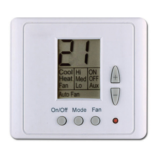
Page 11: Operating Manual
9. Operating manual On/Off • Press the [On/Off] button to activate he thermostat - The word "ON" will appear on display. • Press and hold the [On/Off] button (3 seconds) to deactivate the On/Off Mode On/Off Mode thermostat - The word “OFF” will appear on display. Temperature set-point adjustment •... - Page 12 Modes • Press the [Mode] button to switch between: Cool Cool – “Cool” will appear on display. Heat Heat – “Heat” will appear on display. On/Off Mode On/Off Mode Auto Change-over – “Cool” and “Heat” will appear on display (Available in “P” configuration only – see DIP switch configuration) In Auto change-over mode the active mode will flash.
- Page 13 Auto Fan The Auto Fan mode is available in all modes except for Fan Only mode • Press the [Fan] button to select Auto Fan – “Auto Fan” will appear Cool Cool on display (Press and hold in 2 or 3 speeds configuration). Auto Fan In Auto Fan mode –...
- Page 14 10. RT03 - Hand Held Remote Control - Non-Program - Option General...
- Page 15 Real Time Clock and Day • Press the [Select] button – “CLOCK SET” will flash. • Press the [+] or [-] buttons - the hours will flash. • Adjust the hours using the [+] or [-] buttons. • Press the [Select] button again – the minutes will flash. •...
- Page 16 Stop Time: • Press the [Select] button – “PROGRAM & STOP” will flash on display. • Press the [Select] button - the hours will flash. • Adjust the hours using the [+] or [-] buttons. • Press the [Select] button - the minutes will flash. •...
Need help?
Do you have a question about the ETN24-P-FC-SUPER2 and is the answer not in the manual?
Questions and answers