Table of Contents
Advertisement
Quick Links
Advertisement
Table of Contents

Subscribe to Our Youtube Channel
Related Manuals for Insportline IN 16147


Summary of Contents for Insportline IN 16147
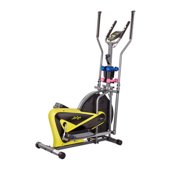
- Page 1 USER MANUAL – EN IN 16147 Elliptical Trainer inSPORTline Airgym...
-
Page 2: Table Of Contents
CONTENTS SAFETY PRECAUTIONS ........................3 HARDWARE LIST ........................... 4 TOOLS ..............................4 PARTS LIST ............................5 EXPLODED DRAWING ........................... 7 ASSEMBLY INSTRUCTIONS ......................... 8 FRONT AND REAR STABILIZER ....................8 LEFT/RIGHT HANDRAIL AND FOOT BARS ................8 RIGHT/LEFT HANDLEBAR ARM ....................9 HANDLEBAR SUPPORT FRAME, HAND PULSE HANDLEBAR, COMPUTER ..... -
Page 3: Safety Precautions
SAFETY PRECAUTIONS • Read this manual carefully before first using and retain it for future reference. Pictures may from product specification. • Observe all instructions and warnings for higher safety. Use it only for intended purpose. • Warm up your muscles before each exercising to avoid an injury. •... -
Page 4: Hardware List
HARDWARE LIST Picture Description Qty. #54 Bolt for left crank 16x89xL23 #56 Spring washer ø20*ø13*2.0 #55 Wave washer ø28*ø17*0.3 #57 Nylon nut for left crank ½” #65 Bolt for right crank 16x89xL23 #56 Spring washer ø20*ø13*2.0 #55 Wave washer ø28*ø17*0.3 #64 Nylon nut for right crank ½”... -
Page 5: Parts List
PARTS LIST Description Qty. Rear stabilizer end cap Rear stabilizer Bolt M10x57 Big curve washer ø10xø25x2.0 Cap nut M10 S17 Phillips sel-tapping screw ST4.2x20 Screw ST4.2x25 Cover cap ø40x ø25x10 Left cover Right cover End cap ø25x1.5 Main frame Sensor L900 mm Phillips self-tapping screw ST4.8x20 Crank nut 7/8”... - Page 6 Plug ø12.1 Tension knob wire Left handlebar Foam grip ø24xø34x280 End cap ø25 Right handlebar Computer Nut M10x1.0 S15 Eyebolt M6x33 U Bracket Nut M6 Nut M10x1*B5 S17 Bushing ø16xø10x20 Fan wheel axle Fan wheel Nut M10x1*B5 S17 Foot bar Bolt for right crank ø16x89xL23 Wave washer ø28x ø17x0.3 Spring washer ø20x ø13x0.2...
-
Page 7: Exploded Drawing
Big arc washer ø8xø20x2.0 Cap nut M8 Spring washer ø8 Washer ø8 End cap 30*20*2.0 Extension wire L650 mm Handlebar support frame Screw M8*35 Form grip ø24xø30x240 Hand pulse Phillips self-tapping screw ST4.2x20 End cap ø25x1.5 Hand pulse handlebar Screw M5x10 Dumbbell rack Screw M6*15 Dumbbell (3 pounds) -
Page 8: Assembly Instructions
ASSEMBLY INSTRUCTIONS 1. FRONT AND REAR STABILIZER • Place the front stabilizer (27) to the front part of the main frame (12). Bolt holes should align. • Attach the front stabilizer (27) to the front curve of the main frame (12) using two cap nuts M10 (5), two curve washers ø10x2.0x ø25 (4) and two bolts M10x57 (3). -
Page 9: Right/Left Handlebar Arm
3. RIGHT/LEFT HANDLEBAR ARM • Insert the left handlebar arm (39) into the handrail arm plastic bushing on the tube of the left handrail (67). Secure it with two bolts (74), two cap nuts (76) and two big curve washers (75). •... -
Page 10: Handlebar Support Frame, Hand Pulse Handlebar, Computer
4. HANDLEBAR SUPPORT FRAME, HAND PULSE HANDLEBAR, COMPUTER • Remove four bolts M8x38 (74), four spring washers ø8 (77) and four washers (78) from the main frame (12). • Attach the middle handlebar support frame (81) onto the main frame (12) with four bolts M8x38 (74), four spring washers ø8 (77) and four washers ø8 (78). -
Page 11: Computer
COMPUTER BATTERY INSTALLATION 1. Remove the battery cover on the computer back. 2. Place two “Size – AA” or “UM-3” batteries into the battery compartment. 3. Make sure the batteries are properly placed and springs are in contact. 4. Attach the cover again. 5. -
Page 12: Functions
FUNCTIONS AUTO ON/OFF When you start exercising or when you push the MODE key, the computer turns on. If you leave this device for 4 minutes, it shuts down automatically. SCAN Push the MODE key until the arrow points to the SCAN. The computer will automatically scan the functions every 5 seconds. -
Page 13: Exercise Instructions
EXERCISE INSTRUCTIONS Each workout should consist of following three phases: warm-up phase, aerobic phase, cool-down phase. Do your workout optimally two or three times a week and have one-day rest between trainings. After several months, you will be able to exercise four or five times a week. WARM-UP PHASE It is very important to do this phase to prepare your body for strenuous exercising. -
Page 14: Aerobic Phase
AEROBIC PHASE During this exercising, the oxygen amount in your muscles and in blood should be increased. It should improve your fitness, especially of heart and lungs. Your heart beats faster and your breathing is deeper while doing this workout. This phase is an indispensable part of your exercising routine. COOL-DOWN PHASE Ate the end of your workout, repeat the warm-up exercises to reduce soreness in stretched muscles. - Page 15 VAT ID: CZ26847264 Phone: +420 556 300 970 E-mail: eshop@insportline.cz reklamace@insportline.cz servis@insportline.cz Web: www.insportline.cz INSPORTLINE s.r.o. Headquarters, Warranty & Service centre: Elektricna 6471, 911 01 Trencin, Slovakia CRN: 36311723 VAT ID: SK2020177082 Phone: +421(0)326 526 701 E-mail: objednavky@insportline.sk reklamacie@insportline.sk servis@insportline.sk...
- Page 16 Web: www.insportline.sk Date of Sale: Stamp and Signature of Seller:...
Need help?
Do you have a question about the IN 16147 and is the answer not in the manual?
Questions and answers