Table of Contents
Advertisement
Quick Links
Advertisement
Table of Contents

Related Manuals for Insportline IN 14169 Combre


Summary of Contents for Insportline IN 14169 Combre
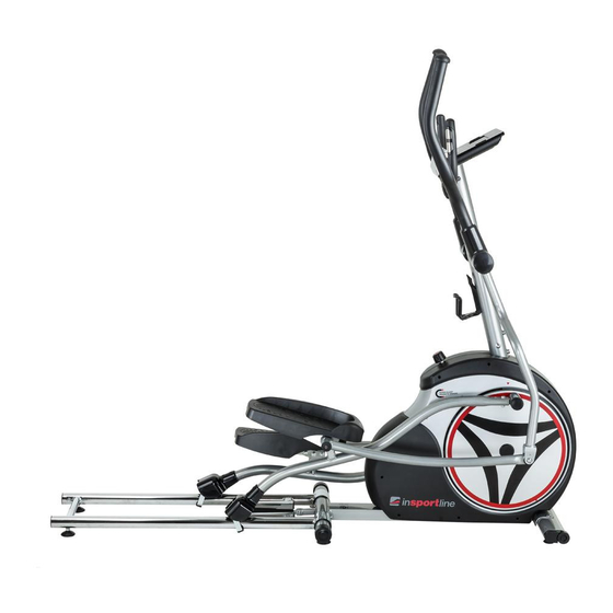
- Page 1 USER MANUAL – EN IN 14169 Elliptical trainer inSPORTline Combre...
-
Page 2: Table Of Contents
CONTENTS SAFETY INSTRUCTIONS ........................3 PARAMETERS ............................3 ASSEMBLY ............................. 4 Tools ..............................4 Parts list ............................... 6 Assembly steps ............................ 7 FOLDING AND UNFOLDING THE MACHINE ..................14 Folding ............................... 14 Unfolding ............................15 CONTROL PANEL ..........................15 Key functions............................15 Operations............................ -
Page 3: Safety Instructions
SAFETY INSTRUCTIONS Read carefully the entire manual before using this product. Retain the manual for future reference. Exercise of a strenuous nature, as is customarily done on this equipment, should not be undertaken without first consulting a physician. No specific health claims can be made or implied as they relate to the equipment. -
Page 4: Assembly
ASSEMBLY Tools H-1 Allen bolt M8*16L (2) H-20 Lock nut M8 (6) - Page 5 H-7 Flat washer Φ10*Φ26 (4) H-2 Allen bolt M8*65L (2) Curved washer (2) H-9 Flat washer H-22 End cap (2) H-17 Allen bolt M8*P1 (2) Φ17,3*Φ25*0,3T (4) H-15 Carriage bolt M8*40L (4) H-16 Curved washer (6) H-19 Flat washer (2) H-21 Screws M5*14L (10) H-8 Teflon washer H-4 Acorn nut M8 (2)
-
Page 6: Parts List
H-18 Bushing Φ16*36,5L (2) Allen key (1) Box spanner (2) Parts list Handlebars (1) Control panel (1) Pedals Pedal arms (1 each) Handlebar post (1) Upper handlebars (1 each) Lower handlebars (1 each) Support tubes (1) Pedal crank arms (1 each) Main base (1) Covers... -
Page 7: Assembly Steps
Power cable (1) User manual and tools list Assembly steps STEP 1 1. Attach the front stabilizer (D-1) to the main base using Allen bolts (H-1). 2. Attach the rear stabilizer (E-1) to the mid-frame protrusions using carriage bolts (H-2), semicircle washers (H-16) and nuts (H-4). - Page 8 4. Attach the U-shaped bracket (F-28) to the right crank arm (F-7) using 2 flat washers (F-33) and 2 screws (F-32) on each side. 5. Attach the covers (???) to the left and right crank arm (F-8/F-7) using screws (F-19). STEP 3 1.
- Page 9 5. Attach the left lower handlebar (I-3) to the axle using a plastic washer (H-8), a flat washer (H- 7) and a nylon screw (H-6). 6. Attach the right lower handlebar (I-4) to the axle using a plastic washer (H-8), a flat washer (H- 7) and a nylon screw (H-6).
- Page 10 3. Attach the lower handlebars (I-3, I-4) to the linkage of the pedal arms (F-1, F-2) using Allen bolts (H-17), bushing (H-18), flat washers (H-19) and nuts (H-20) per side. Make sure the direction is the same as in the drawing. 4.
- Page 11 3. Remove the pre-installed screws (I-8) on the left and right lower handlebar (I-3/I-4) first. 4. Attach the covers (F-29/F-30) for the left and right upper handlebars (I-1/I-2) and fasten them with 4 screws (I-8). STEP 6 1. Attach the front handlebar (B-1) onto the handlebar post (C-1) using a flat washer (H-11), a spring washer (H-12) and a fixing bolt (H-13).
- Page 12 2. Place the plastic cover (H-14) on the front handlebar (B-1). 3. Thread the hand pulse wire (B-5) through the handlebar post hole.
- Page 13 STEP 7 1. Remove the preinstalled screws on the control panel (A-2) first. 2. Connect the control panel cable (C-2) and the hand pulse wire (B-5) to the control panel (A-1). Then attach the control panel (A-1) to the console panel bracket with enclosed screws (A-2).
-
Page 14: Folding And Unfolding The Machine
FOLDING AND UNFOLDING THE MACHINE Folding Find the knob on the front chain cover and turn in clockwise (so that the two arrows marks line up). Lift up the linkage tube until you hear a click. -
Page 15: Unfolding
Unfolding Pull the linkage tube forward. Kick the foldable cylinder in the area marked by this yellow sticker. Continue to press with your foot until the linkage arm unfolds completely. NOTE: Make sure the linkage arm, is completely on the ground. CONTROL PANEL Key functions MODE... -
Page 16: Operations
Select a training mode or increase a value. DOWN Select a training mode or decease a value. BODY FAT Measure your body fat. Operations 1. Connect the machine to the power supply. The LCD display will light up for 2 seconds and a long chime will sound. - Page 17 7. Programs Press UP and DOWN to select one of the 12 programs and press MODE to confirm. The user may set target LEVEL, TIME, DISTANCE, CALORIES and PULSE with the UP and DOWN keys. 8. Heart rate control (H.R.C.) Before an exercise in the H.R.C.
-
Page 18: Using An Elliptical Trainer
11. Body fat: This function measures your body fat percentage and BMI. At the end of your workout, press the BODY FAT key and grab both handgrips. The heart rate sensor input must be maintained while measuring the body fat. The computer will display --- after 8 seconds and then display a body fat advice symbol, body fat percentage and BMI for 30 seconds. -
Page 19: Exploded Drawing
EXPLODED DRAWING... -
Page 20: Components List
COMPONENTS LIST Description Description Console set SM2743-67 with Cap for round disc screw Screw M5*10L Disc set Front handlebar set Flat washer Front handlebar Screw M4x14L Hand pulse Nuts M10xP1.25x10T End cap for front handlebar Screw M4x50L Foam grip for front handlebar Screw 3/16 Pulse wire for front handlebar Sensor holder... - Page 21 Adjustable pad for front stabilizer Nylon nuts M8 Stoppers for front stabilizer Flat washer Rear stabilizer set Flat washer Rear stabilizer Bolts & nuts pack Allen bolt M6xP1.0x12L Screw M8x16 End cap for rear stabilizer Screw M8xP1.25x65L Adjustable pad for rear stabilizer Nut M8 Left rail Nylon screw M8xP1.0x20L...
- Page 22 Bushing Lower handlebar (Right) Foam grip for upper Connector bracket of pedal tube handlebar Allen bolt M8xP1.25x35L Cap for upper handlebar Flat washer Bushing Nylon nut M8 Screw M5xP0.8x14L Wave washer Gear box set Bushing Magnetic set Cover for roller wheel Hex.
-
Page 23: Terms And Conditions Of Warranty, Warranty Claims
Cable upper Hex. Screw M8xP1.25x20L C-type ring Nylon nut M8 Wave washer Flat Washer Flat washer Spring Bearing 6004RS Hex. Screw M6xP1.0x100L Belt Flat Washer Left chain cover Hex. Screw M6xP1.0x12L Right chain cover Idler wheel Round disc TERMS AND CONDITIONS OF WARRANTY, WARRANTY CLAIMS General Conditions of Warranty and Definition of Terms All Warranty Conditions stated hereunder determine Warranty Coverage and Warranty Claim Procedure. - Page 24 Warranty & Service Centre: Cermenska 486, 749 01 Vitkov, Czech Republic CRN: 26847264 VAT ID: CZ26847264 Phone: +420 556 300 970 E-mail: eshop@insportline.cz reklamace@insportline.cz servis@insportline.cz Web: www.insportline.cz INSPORTLINE s.r.o. Headquarters, Warranty & Service centre: Elektricna 6471, 911 01 Trencin, Slovakia CRN: 36311723...
- Page 25 VAT ID: SK2020177082 Phone: +421(0)326 526 701 E-mail: objednavky@insportline.sk reklamacie@insportline.sk servis@insportline.sk Web: www.insportline.sk Date of Sale: Stamp and Signature of Seller:...