
Subscribe to Our Youtube Channel
Related Manuals for Aaeon AEC-6860


Summary of Contents for Aaeon AEC-6860
- Page 1 E m b e d d e d C o n t r o l l e r A E C - 6 8 6 0 AEC-6860 Fanless Embedded Controller ® Intel Core 2 Duo Processor with Gigabit Ethernet, 4 COMs, Audio, VGA, DVI, LVDS, TV-out AEC-6860 Manual 3rd Ed. June 2010...
-
Page 2: Copyright Notice
AAEON assumes no liabilities resulting from errors or omissions in this document, or from the use of the information contained herein. AAEON reserves the right to make changes in the product design without notice to its users. - Page 3 E m b e d d e d C o n t r o l l e r A E C - 6 8 6 0 Acknowledgments • Award is a trademark of Award Software International, Inc. • ™ CompactFlash is a trademark of the Compact Flash Association.
-
Page 4: Packing List
A E C - 6 8 6 0 Packing List Before you begin operating your PC, please make sure that the following materials have been shipped: AEC-6860 Embedded Controller Keyboard & mouse cable Phoenix Power Connector Wallmount Brackets Audio Cable... - Page 5 E m b e d d e d C o n t r o l l e r A E C - 6 8 6 0 Safety & Warranty 1. Read these safety instructions carefully. 2. Keep this user's manual for later reference. 3.
- Page 6 E m b e d d e d C o n t r o l l e r A E C - 6 8 6 0 The equipment does not work well, or you cannot get it to work according to the user’s manual. The equipment has been dropped and damaged.
- Page 7 E m b e d d e d C o n t r o l l e r A E C - 6 8 6 0 Below Table for China RoHS Requirements 产品中有毒有害物质或元素名称及含量 AAEON Boxer/ Industrial System 有毒有害物质或元素 部件名称 铅...
-
Page 8: Table Of Contents
E m b e d d e d C o n t r o l l e r A E C - 6 8 6 0 Contents Chapter 1 General Information 1.1 Introduction..............1-2 1.2 Features ..............1-4 1.3 Specifications ............1-5 Chapter 2 Hardware Installation 2.1 Dimension .............. - Page 9 E m b e d d e d C o n t r o l l e r A E C - 6 8 6 0 Appendix A Programming The Watchdog Timer A.1 Programming ............A-2 A.2 IT8712 Watchdog Timer Initial Program ....A-6 Appendix B I/O Information B.1 I/O Address Map ..........B-2 B.2 1...
-
Page 10: Chapter 1 General Information
E m b e d d e d C o n t r o l l e r A E C - 6 8 6 0 Chapter General Information 1- 1 Chapter 1 General Information... -
Page 11: Introduction
Being a control center, the AEC-6860 is suitable for public multimedia entertainment services. Equipped with a high efficiency heat conduction mechanism. The AEC-6860 is compact in size but has attractive and flexible extension capabilities such as 4 USB2.0 ports, VGA, TV-out, DVI, Audio, 4 COM ports. - Page 12 A E C - 6 8 6 0 Stable Design for Rugged Environment The AEC-6860 is designed for rugged environments due to the following reasons; first, it can withstand tough vibration testing up to 5G rms. With the anti-vibration hard drive device option, the AEC-6860 can be used in high vibration environments.
-
Page 13: Features
E m b e d d e d C o n t r o l l e r A E C - 6 8 6 0 1.2 Features • ® Fanless Design with Intel Core 2 Duo Processor • VGA, DVI, LVDS, S-Video Output. •... -
Page 14: Specifications
E m b e d d e d C o n t r o l l e r A E C - 6 8 6 0 1.3 Specifications System • ® CPU: Intel Core 2 Duo Processor up to 1.6GHz ®... -
Page 15: Mechanical And Environmental
E m b e d d e d C o n t r o l l e r A E C - 6 8 6 0 (COM2) • Audio: MIC / Line In / Line Out (by extension cable) • USB: 4 USB 2.0 ports •... -
Page 16: Dimension
E m b e d d e d C o n t r o l l e r A E C - 6 8 6 0 • Dimension: 13.22” (W) x 11.57” (H) x 10.24” (D) (336mm x 294mm x 260mm) •... -
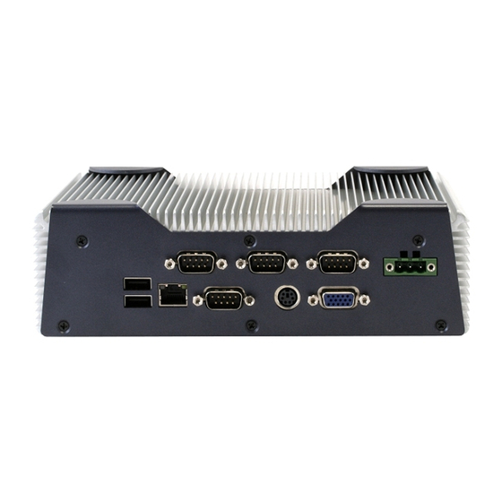
Page 17: Front Side
E m b e d d e d C o n t r o l l e r A E C - 6 8 6 0 Front Side Rear Side Chapter 1 General Information... - Page 18 E m b e d d e d C o n t r o l l e r A E C - 6 8 6 0 Chapter Hardware Installation Chapter 2 Hardware Installation...
- Page 19 E m b e d d e d C o n t r o l l e r A E C - 6 8 6 0 2.1 Dimension 2 - 2 Chapter 2 Hardware Installation...
-
Page 20: Com2 Ri/+5V/+12V Selection (Jp3)
E m b e d d e d C o n t r o l l e r A E C - 6 8 6 0 2.2 COM2 RI/+5V/+12V Selection (JP3) Function +12V 2 - 3 Chapter 2 Hardware Installation... -
Page 21: Com2 Rs-232/422/485 Serial Port Connector
E m b e d d e d C o n t r o l l e r A E C - 6 8 6 0 2.3 COM2 RS-232/422/485 Serial Port Connector Different devices implement the RS-232/422/485 standard in different ways. If you are having problems with a serial device, be sure to check the pin assignments below for the connector. -
Page 22: Lvds Pin Definition
E m b e d d e d C o n t r o l l e r A E C - 6 8 6 0 2.5 LVDS Pin Definition Signal Signal BKLEN TXUCLK BKLCTL SDATA SCLK TXLCLK# TXL1# TXLCLK TXL1 TXL0# TXL0... -
Page 23: Ram Module Installation
E m b e d d e d C o n t r o l l e r A E C - 6 8 6 0 2.6 RAM Module Installation Step 1: Take off the lid from the bottom of the chassis by loosening the screws. - Page 24 E m b e d d e d C o n t r o l l e r A E C - 6 8 6 0 Step 2: Cover the chips with a thermal pad 2 - 7 Chapter 2 Hardware Installation...
-
Page 25: Cd-Rom And 2.5" Hdd Kit Installation
E m b e d d e d C o n t r o l l e r A E C - 6 8 6 0 Step 3: Place the lid back on and lock with screws. 2.7 CD-ROM and 2.5” HDD Kit Installation CD-ROM and 2.5”... - Page 26 E m b e d d e d C o n t r o l l e r A E C - 6 8 6 0 Step 2: Fasten the CD-ROM to the disk bracket with screws. Step 3: Fasten the Riser Card and the CD-ROM with screws. Riser Card Step 4: Fasten the 2.5”...
- Page 27 E m b e d d e d C o n t r o l l e r A E C - 6 8 6 0 Step 5: Insert the SATA cable and IDE cable into the slots on the Riser Card and the 2.5”...
- Page 28 E m b e d d e d C o n t r o l l e r A E C - 6 8 6 0 Step 6: Place the CD-ROM and HDD kit into the suitable plate and then reverse it.
- Page 29 E m b e d d e d C o n t r o l l e r A E C - 6 8 6 0 Step 2: Insert the other side of IDE cable into the slot on the bottom of the chassis.
- Page 30 E m b e d d e d C o n t r o l l e r A E C - 6 8 6 0 Step 3: Combine the chassis with the CD-ROM and 2.5” HDD kit plate. Then lock with screws. 2 - 13 Chapter 2 Hardware Installation...
-
Page 31: Dual 2.5" Hdd Kit Installation
E m b e d d e d C o n t r o l l e r A E C - 6 8 6 0 2.8 Dual 2.5” HDD Kit Installation HDD Kit Combination Step 1: Get the bracket ready. Attach the rubber shock absorbers with the bracket as illustration shown below. - Page 32 E m b e d d e d C o n t r o l l e r A E C - 6 8 6 0 Step 4: Insert the HDD cable into the slot on the HDD module. SATA HDD Cable Power Cable Step 5: Place the HDD kit into the HDD kit housing and then screw the HDD kit onto the HDD kit housing.
- Page 33 E m b e d d e d C o n t r o l l e r A E C - 6 8 6 0 Cable Insertion Step 1: Open the HDD cover by loosening the screws on the bottom of the chassis.
- Page 34 E m b e d d e d C o n t r o l l e r A E C - 6 8 6 0 Step 3: Combine the chassis with the HDD kit housing and then lock with screws.
-
Page 35: Hdd Kit Installation
E m b e d d e d C o n t r o l l e r A E C - 6 8 6 0 2.9 3.5” HDD Kit Installation HDD Kit Combination Step 1: Get the HDD module ready. Insert power cable and HDD cable into the slots on the HDD module. - Page 36 E m b e d d e d C o n t r o l l e r A E C - 6 8 6 0 Step 4: Fasten the HDD module to the bracket with screws. Step 5: Get the screws ready, by matching them up with a washer. Meanwhile, place the HDD kit into the HDD kit housing and then screw the HDD kit to the HDD kit housing.
- Page 37 E m b e d d e d C o n t r o l l e r A E C - 6 8 6 0 Cable Insertion Step 1: Open the HDD cover by loosening the screws on the bottom of the chassis.
- Page 38 E m b e d d e d C o n t r o l l e r A E C - 6 8 6 0 Step 3: Combine the chassis with the HDD kit housing and then lock with screws.
-
Page 39: Wallmount Bracket Installation
E m b e d d e d C o n t r o l l e r A E C - 6 8 6 0 2.10 Wallmount Bracket Installation Fasten the brackets with the appropriate screws. 2 - 22 Chapter 2 Hardware Installation... -
Page 40: Chapter 3 Award Bios Setup
E m b e d d e d C o n t r o l l e r A E C - 6 8 6 0 Chapter Award BIOS Setup Chapter 3 Award BIOS Setup 3-1... - Page 41 3. The CMOS memory has lost power and the configuration information has been erased. The AEC-6860 CMOS memory has an integral lithium battery backup for data retention. However, you will need to replace the complete unit when it finally runs down.
- Page 42 E m b e d d e d C o n t r o l l e r A E C - 6 8 6 0 3.2 Award BIOS Setup Awards BIOS ROM has a built-in Setup program that allows users to modify the basic system configuration.
- Page 43 E m b e d d e d C o n t r o l l e r A E C - 6 8 6 0 Integrated Peripherals Use this menu to specify your settings for integrated peripherals. (Primary slave, secondary slave, keyboard, mouse etc.) Power Management Setup Use this menu to specify your settings for power management.
-
Page 44: Save And Exit Setup
Save CMOS value changes to CMOS and exit setup. Exit Without Saving Abandon all CMOS value changes and exit setup. You can refer to the "AAEON BIOS Item Description.pdf" file in the CD for the meaning of each setting in this chapter. -
Page 45: Chapter 4 Driver Installation
E m b e d d e d C o n t r o l l e r A E C - 6 8 6 0 Chapter Driver Installation 4 - 1 Chapter 4 Driver Installation... - Page 46 E m b e d d e d C o n t r o l l e r A E C - 6 8 6 0 The AEC-6860 comes with a CD-ROM that contains all drivers and utilities that meet your needs.
- Page 47 E m b e d d e d C o n t r o l l e r A E C - 6 8 6 0 4.1 Installation Insert the AEC-6860 CD-ROM into the CD-ROM Drive. And install the drivers from Step 1 to Step 5 in order. Step 1 – Install Intel INF Driver 1.
- Page 48 Sil3132 and treat it as a third-part driver. Please follow the steps below to install the driver with the Operating System. 1. Creating a Drive Disk: copy the SATA driver from AAEON CD to floppy disk before install the OS Click on Step 5 - Sil3132 SATA Driver Click on SiI 3132 BASE Driver (For_BIOS_7.3.13)
- Page 49 E m b e d d e d C o n t r o l l e r A E C - 6 8 6 0 screen for only 5 seconds. If you did not press F6 in time, please restart your computer. 5.
- Page 50 E m b e d d e d C o n t r o l l e r A E C - 6 8 6 0 9. Follow the on-screen instructions to complete the installation. After finish installing OS, you have to install Silicon Raid Management Utility.
-
Page 51: Appendix A Programming The Watchdog Timer
E m b e d d e d C o n t r o l l e r A E C - 6 8 6 0 Appendix Programming the Watchdog Timer Appendix A Programming the Watchdog Timer... -
Page 52: Programming
E m b e d d e d C o n t r o l l e r A E C - 6 8 6 0 A.1 Programming AEC-6860 utilizes ITE 8712 chipset as its watchdog timer controller. Below are the procedures to complete its configuration and the... - Page 53 E m b e d d e d C o n t r o l l e r A E C - 6 8 6 0 registers; (3) Exit the MB PnP Mode. Undesired result may occur if the MB PnP Mode is not exited normally. (1) Enter the MB PnP Mode To enter the MB PnP Mode, four special I/O write operations are to be performed during Wait for Key state.
- Page 54 E m b e d d e d C o n t r o l l e r A E C - 6 8 6 0 WatchDog Timer Configuration Registers Configure Control (Index=02h) This register is write only. Its values are not sticky; that is to say, a hardware reset will automatically clear the bits, and does not require the software to clear them.
- Page 55 E m b e d d e d C o n t r o l l e r A E C - 6 8 6 0 WatchDog Timer Control Register (Index=71h, Default=00h) WatchDog Timer Configuration Register (Index=72h, Default=00h) WatchDog Timer Time-out Value Register (Index=73h, Default=00h) Appendix A Programming the Watchdog Timer...
-
Page 56: It8712 Watchdog Timer Initial Program
E m b e d d e d C o n t r o l l e r A E C - 6 8 6 0 A.2 IT8712 Watchdog Timer Initial Program .MODEL SMALL .CODE Main: CALL Enter_Configuration_mode CALL Check_Chip mov cl, 7 call Set_Logic_Device ;time setting... - Page 57 E m b e d d e d C o n t r o l l e r A E C - 6 8 6 0 ; game port enable mov cl, 9 call Set_Logic_Device Initial_OK: CALL Exit_Configuration_mode MOV AH,4Ch INT 21h Enter_Configuration_Mode PROC NEAR MOV SI,WORD PTR CS:[Offset Cfg_Port]...
- Page 58 E m b e d d e d C o n t r o l l e r A E C - 6 8 6 0 Exit_Configuration_Mode ENDP Check_Chip PROC NEAR MOV AL,20h CALL Read_Configuration_Data CMP AL,87h JNE Not_Initial MOV AL,21h CALL Read_Configuration_Data CMP AL,12h JNE Not_Initial...
- Page 59 E m b e d d e d C o n t r o l l e r A E C - 6 8 6 0 MOV DX,WORD PTR CS:[Cfg_Port+06h] IN AL,DX Read_Configuration_Data ENDP Write_Configuration_Data PROC NEAR MOV DX,WORD PTR CS:[Cfg_Port+04h] OUT DX,AL XCHG AL,AH MOV DX,WORD PTR CS:[Cfg_Port+06h]...
- Page 60 E m b e d d e d C o n t r o l l e r A E C - 6 8 6 0 push ax push cx xchg al,cl mov cl,07h call Superio_Set_Reg pop cx pop ax Set_Logic_Device endp ;Select 02Eh->Index Port, 02Fh->Data Port Cfg_Port DB 087h,001h,055h,055h...
-
Page 61: Appendix B I/O Information
E m b e d d e d C o n t r o l l e r A E C - 6 8 6 0 Appendix I/O Information Appendix B I/O Information... -
Page 62: I/O Address Map
E m b e d d e d C o n t r o l l e r A E C - 6 8 6 0 B.1 I/O Address Map Appendix B I/O Information... -
Page 63: St Mb Memory Address Map
E m b e d d e d C o n t r o l l e r A E C - 6 8 6 0 B.2 1 MB Memory Address Map Appendix B I/O Informaion... -
Page 64: Irq Mapping Chart
E m b e d d e d C o n t r o l l e r A E C - 6 8 6 0 B.3 IRQ Mapping Chart B.4 DMA Channel Assignments Appendix B I/O Information...
Need help?
Do you have a question about the AEC-6860 and is the answer not in the manual?
Questions and answers