
Related Manuals for Aaeon ACP-5185


Summary of Contents for Aaeon ACP-5185
- Page 1 M u l t i - T o u c h P a n e l P C A C P - 5 1 8 5 ACP-5185 ® 18.5” Intel Core i7/i5 Processor High Brightness Fanless Multi-Touch Panel PC ACP-5185 Manual 4th Ed January 2013...
-
Page 2: Copyright Notice
AAEON, assumes no liabilities resulting from errors or omissions in this document, or from the use of the information contained herein. AAEON reserves the right to make changes in the product design without notice to its users. - Page 3 M u l t i - T o u c h P a n e l P C A C P - 5 1 8 5 Acknowledgments ® ® Intel , Core are registered trademarks of Intel Corporation. ® ®...
-
Page 4: Packing List
A C P - 5 1 8 5 Packing List Before you begin installing your Panel PC, please make sure that the following items have been shipped: ACP-5185 Infotainment Multi-Touch Panel PC HDD screws Product DVD Contains User’s Manual (in PDF format), Drivers and... - Page 5 M u l t i - T o u c h P a n e l P C A C P - 5 1 8 5 Safety & Warranty 1. Read these safety instructions carefully. 2. Keep this user's manual for later reference. 3.
- Page 6 M u l t i - T o u c h P a n e l P C A C P - 5 1 8 5 14. If any of the following situations arises, get the equipment checked by service personnel: a.
- Page 7 M u l t i - T o u c h P a n e l P C A C P - 5 1 8 5 Classification 1. Degree of production against electric shock: not classified 2. Degree of protection against the ingress of water: IPX0 3.
- Page 8 M u l t i - T o u c h P a n e l P C A C P - 5 1 8 5 This device complies with Part 15 FCC Rules. Operation is subject to the following two conditions: (1) this device may not cause harmful interference, and (2) this device must accept any interference received...
- Page 9 M u l t i - T o u c h P a n e l P C A C P - 5 1 8 5 UL Module Description ACP-5185 AC modules are developed to suitable for the Classification Mark requirement...
- Page 10 M u l t i - T o u c h P a n e l P C A C P - 5 1 8 5 Safety Symbol Description The following safety symbols are further explanations for your reference. Medical equipment with respect to electric shock, fire and mechanical hazards only in accordance with UL 60601-1, and CAN/CSA C22.2 NO.
- Page 11 M u l t i - T o u c h P a n e l P C A C P - 5 1 8 5 Below Table for China RoHS Requirements 产品中有毒有害物质或元素名称及含量 AAEON Panel PC/ Workstation 有毒有害物质或元素 部件名称 铅...
-
Page 12: Table Of Contents
1.4 General Information........... 1-7 Chapter 2 Hardware Installation 2.1 Safety Precautions ............ 2-2 2.2 A Quick Tour of the ACP-5185........2-3 2.3 2.5” Hard Disk Drive (HDD) Installation ....2-6 Chapter 3 AMI BIOS Setup 3.1 System Test and Initialization ........3-2 3.2 AMI BIOS Setup. - Page 13 M u l t i - T o u c h P a n e l P C A C P - 5 1 8 5 B.3 IRQ Mapping Chart ..........B-5 B.4 DMA Channel Assignments........B-5 Appendix C Miscellanea C.1 General Cleaning Tips .......... C-2 C.2 Cleaning Tools............
- Page 14 M u l t i - T o u c h P a n e l P C A C P - 5 1 8 5 Chapter General Information Chapter 1 General Information...
-
Page 15: Chapter 1 General Information
The ACP-5185 includes all the features of a powerful computer into a slim and attractive chassis. The ACP-5185 has 300 nits TFT display with 1366 x 768 resolution. This model equips two-point Multi-Touch Window design and is easy to clean. -
Page 16: Features
M u l t i - T o u c h P a n e l P C A C P - 5 1 8 5 1.2 Features 18.5” WXGA (1366 x 768) Fanless TFT LCD Display Easy-To-Clean: Multi-Touch Window Design (Two-Point) ... -
Page 17: Specification
M u l t i - T o u c h P a n e l P C A C P - 5 1 8 5 1.3 Specification System ® Onboard Intel Core™ i7/i5 Processor Processor System Memory DDR3 SODIMM x 1, Max. - Page 18 M u l t i - T o u c h P a n e l P C A C P - 5 1 8 5 Net Weight 15.4 lb (7 kg) Gross Weight 19.8 lb (9 kg) Environmental ...
- Page 19 M u l t i - T o u c h P a n e l P C A C P - 5 1 8 5 Backlight MTBF (Hours) 50,000 Touchscreen Type Projected Capacitive Multi-Touch (Windows® 7) Light Transmission ...
-
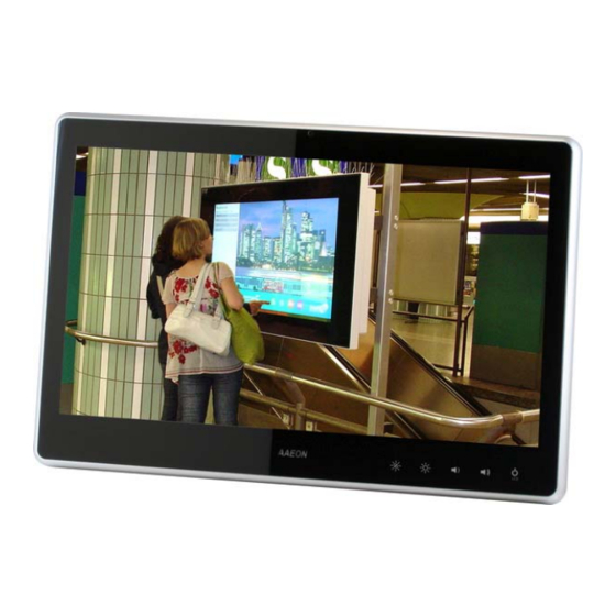
Page 20: General Information
M u l t i - T o u c h P a n e l P C A C P - 5 1 8 5 1.4 General Information 1.3M Camera (Optional) LCD On/Off Volume+ Volume- RFID (Optional) Brightness+ Brightness- Chapter 1 General Information... - Page 21 M u l t i - T o u c h P a n e l P C A C P - 5 1 8 5 VESA 100 Mounting Holes Mounting Holes Chapter 1 General Information...
- Page 22 M u l t i - T o u c h P a n e l P C A C P - 5 1 8 5 RS-232 Line-out Power Input Power Switch Smart Card Reader USB x 4 (Optional) USB x 2 LAN x 2 Antenna (Optional)
-
Page 23: Chapter 2 Hardware Installation
M u l t i - T o u c h P a n e l P C A C P - 5 1 8 5 Chapter Hardware Installation Chapter 2 Hardware Installation... -
Page 24: Safety Precautions
M u l t i - T o u c h P a n e l P C A C P - 5 1 8 5 2.1 Safety Precautions Always completely disconnect the power cord from your board whenever you are working on it. -
Page 25: A Quick Tour Of The Acp-5185
M u l t i - T o u c h P a n e l P C A C P - 5 1 8 5 2.2 A Quick Tour of the ACP-5185 Front Rear Chapter 2 Hardware Installation... - Page 26 M u l t i - T o u c h P a n e l P C A C P - 5 1 8 5 Cable Cover (Optional) Note 1: You may turn on the power by cutting and destroying the protective cover as it shows below.
- Page 27 M u l t i - T o u c h P a n e l P C A C P - 5 1 8 5 Note 2: The “Anti-Drop Kit” can help on preventing the cable drop from the connector Chapter 2 Hardware Installation...
-
Page 28: Hard Disk Drive (Hdd) Installation
M u l t i - T o u c h P a n e l P C A C P - 5 1 8 5 2.3 2.5” Hard Disk Drive (HDD) Installation Step 1: Unscrew the rear cover screws (15 screws) Step 2: Remove EMI Cover (5 screws) Chapter 2 Hardware Installation... - Page 29 M u l t i - T o u c h P a n e l P C A C P - 5 1 8 5 Step 3: Remove HDD Bracket (4 screws) Step 4: Get the HDD and HDD Bracket ready Chapter 2 Hardware Installation...
- Page 30 M u l t i - T o u c h P a n e l P C A C P - 5 1 8 5 Step 5: Fasten the four screws to fix HDD Bracket and HDD Step 6: Connect the SATA and power cables to the HDD and fasten the four screws to fix the HDD Bracket Chapter 2 Hardware Installation...
-
Page 31: Chapter 3 Ami Bios Setup
M u l t i - T o u c h P a n e l P C A E C - 5 1 8 5 Chapter BIOS Setup Chapter 3 AMI BIOS Setup 3-1... -
Page 32: System Test And Initialization
M u l t i - T o u c h P a n e l P C A E C - 5 1 8 5 3.1 System Test and Iinitialization These routines test and initialize board hardware. If the routines encounter an error during the tests, you will either hear a few short beeps or see an error message on the screen. -
Page 33: Ami Bios Setup
M u l t i - T o u c h P a n e l P C A E C - 5 1 8 5 3.2 AMI BIOS Setup AMI BIOS ROM has a built-in Setup program that allows users to modify the basic system configuration. -
Page 34: Setup Menu
M u l t i - T o u c h P a n e l P C A E C - 5 1 8 5 Setup Menu Setup submenu: Main Chapter 3 AMI BIOS Setup 3-4... - Page 35 M u l t i - T o u c h P a n e l P C A E C - 5 1 8 5 Setup submenu: Advanced Options summary: Launch 82577 PXE Disabled Optimal Default, Failsafe Default OpROM Enabled En/Disable Legacy Boot Option for 82577.
-
Page 36: Pci Subsystem Setting
M u l t i - T o u c h P a n e l P C A E C - 5 1 8 5 PCI Subsystem Setting Options summary: PCI Latency Timer 32 PCI Bus Clocks Optimal Default, Failsafe Default 64 PCI Bus Clocks 96 PCI Bus Clocks 128 PCI Bus Clocks... -
Page 37: Acpi Settings
M u l t i - T o u c h P a n e l P C A E C - 5 1 8 5 ACPI Settings Options summary: Enable ACPI Auto Disabled Optimal Default, Failsafe Default Configuration Enabled Enables or Disables BIOS ACPI Auto Configuration Enable Hibernation Disabled... - Page 38 M u l t i - T o u c h P a n e l P C A E C - 5 1 8 5 S5 RTC Wake Settings (Fixed Time) Options summary: Wake system with Disabled Optimal Default, Failsafe Default Fixed Time Enabled En/Disable System wake on alarm event.
- Page 39 M u l t i - T o u c h P a n e l P C A E C - 5 1 8 5 S5 RTC Wake Settings (Dynamic Time) Options summary: Wake system with Disabled Optimal Default, Failsafe Default Dynamic Time Enabled En/Disable System wake on alarm event.
-
Page 40: Cpu Configuration
M u l t i - T o u c h P a n e l P C A E C - 5 1 8 5 CPU Configuration Options summary: Hyper-Threading Disabled Enabled Optimal Default, Failsafe Default Enabled for Windows XP and Linux (OS optimized for Hyper-Threading Technology) and Disabled for other OS (OS not optimized for Hyper-Threading Technology). - Page 41 M u l t i - T o u c h P a n e l P C A E C - 5 1 8 5 IDE Configuration (IDE) Chapter 3 AMI BIOS Setup 3-11...
- Page 42 M u l t i - T o u c h P a n e l P C A E C - 5 1 8 5 IDE Configuration (AHCI) Chapter 3 AMI BIOS Setup 3-12...
- Page 43 M u l t i - T o u c h P a n e l P C A E C - 5 1 8 5 IDE Configuration (RAID) Options summary: SATA Mode Disable Optimal Default, Failsafe Default AHCI RAID IDE: Configure SATA controllers as legacy IDE AHCI: Configure SATA controllers to operate in AHCI mode RAID: Configure SATA controllers to operate in RAID mode...
-
Page 44: Intel Igd Swsci Opregion
M u l t i - T o u c h P a n e l P C A E C - 5 1 8 5 Intel IGD SWSCI OpRegion Chapter 3 AMI BIOS Setup 3-14... - Page 45 M u l t i - T o u c h P a n e l P C A E C - 5 1 8 5 Options summary: DVMT/FIXED Memory 128MB 256MB Optimal Default, Failsafe Default Maximum Select DVMT/FIXED Mode Memory size used by Internal Graphics Device IGD –...
-
Page 46: Usb Configuration
M u l t i - T o u c h P a n e l P C A E C - 5 1 8 5 USB Configuration Options summary: Device Name (Emulation Auto Optimal Default, Failsafe Default Type) Floppy Forced FDD Hard Disk CDROM... -
Page 47: Super Io Configuration
M u l t i - T o u c h P a n e l P C A E C - 5 1 8 5 Super IO Configuration Chapter 3 AMI BIOS Setup 3-17... -
Page 48: Serial Port 1 Configuration
M u l t i - T o u c h P a n e l P C A E C - 5 1 8 5 Serial Port 1 Configuration Options summary: Serial Port Disabled Enabled Default Allows BIOS to En/Disable correspond serial port. Change Settings Auto Default... - Page 49 M u l t i - T o u c h P a n e l P C A E C - 5 1 8 5 H/W Monitor Chapter 3 AMI BIOS Setup 3-19...
-
Page 50: Amt Configuration
M u l t i - T o u c h P a n e l P C A E C - 5 1 8 5 AMT Configuration Options summary: Disabled Enabled Optimal Default, Failsafe Default Intel AMT Enable/Disable Unconfigure AMT/ME Disabled Optimal Default, Failsafe Default Enabled... - Page 51 M u l t i - T o u c h P a n e l P C A E C - 5 1 8 5 CompactFlash Controller Configuration Options summary: ATA Controller Disabled IDE Mode Optimal Default, Failsafe Default Select an operative mode for ATA controller Chapter 3 AMI BIOS Setup 3-21...
- Page 52 M u l t i - T o u c h P a n e l P C A E C - 5 1 8 5 Serial Port Condole Redirection Options summary: Console Redirection Disabled Optimal Default, Failsafe Default Enabled Console Redirection Enable/Disable Chapter 3 AMI BIOS Setup 3-22...
- Page 53 M u l t i - T o u c h P a n e l P C A E C - 5 1 8 5 Setup submenu: Chipset Chapter 3 AMI BIOS Setup 3-23...
-
Page 54: North Bridge
M u l t i - T o u c h P a n e l P C A E C - 5 1 8 5 North Bridge Chapter 3 AMI BIOS Setup 3-24... - Page 55 M u l t i - T o u c h P a n e l P C A E C - 5 1 8 5 Options summary: Low MMIO Align Optimal Default, Failsafe Default 1024M Low MMIO resource align at 64MB/1024MB Initiate Graphic Adapter PCI/IGD PCI/PEG...
-
Page 56: South Bridge
M u l t i - T o u c h P a n e l P C A E C - 5 1 8 5 South Bridge Chapter 3 AMI BIOS Setup 3-26... - Page 57 M u l t i - T o u c h P a n e l P C A E C - 5 1 8 5 Options summary: 82577 SMBus Controller Disabled Enabled Optimal Default, Failsafe Default 82577 SMBus Controller Enable/Disable 82577 GbE Controller Disabled Enabled...
- Page 58 M u l t i - T o u c h P a n e l P C A E C - 5 1 8 5 ME Subsystem Options summary: ME Subsystem Disabled Enabled Optimal Default, Failsafe Default ME Subsystem Enable/Disable End of Post Message Disabled Enabled...
- Page 59 M u l t i - T o u c h P a n e l P C A E C - 5 1 8 5 Setup submenu: Boot Chapter 3 AMI BIOS Setup 3-29...
- Page 60 M u l t i - T o u c h P a n e l P C A E C - 5 1 8 5 Options summary: Quiet Boot Disabled Optimal Default, Failsafe Default Enabled En/Disable showing boot logo. Setup Prompt Timeout 1~65535 (1) Optimal Default, Failsafe Default...
- Page 61 M u l t i - T o u c h P a n e l P C A E C - 5 1 8 5 BBS Priorities Chapter 3 AMI BIOS Setup 3-31...
- Page 62 M u l t i - T o u c h P a n e l P C A E C - 5 1 8 5 Security Change User/Supervisor Password You can install a Supervisor password, and if you install a supervisor password, you can then install a user password.
- Page 63 M u l t i - T o u c h P a n e l P C A E C - 5 1 8 5 Setup submenu: Exit Chapter 3 AMI BIOS Setup 3-33...
-
Page 64: Chapter 4 Driver Installation
M u l t i - T o u c h P a n e l P C A C P - 5 1 8 5 Chapter Driver Installation Chapter 4 Driver Installation... - Page 65 M u l t i - T o u c h P a n e l P C A C P - 5 1 8 5 The ACP-5185 comes with an AutoRun DVD-ROM that contains all drivers and utilities that can help you to install the driver automatically.
- Page 66 M u l t i - T o u c h P a n e l P C A C P - 5 1 8 5 4.1 Installation: Insert the ACP-5185 DVD-ROM into the DVD-ROM drive. Then install the drivers from Step 1 to Step 9 in order. Step 1 – Install Chipset Driver Click on the Step1–CHIPSET folder and double click on...
- Page 67 M u l t i - T o u c h P a n e l P C A C P - 5 1 8 5 Step 4 –Install ME Driver Click on the Step4–ME folder and double click on the Setup.exe file Follow the instructions that the window shows The system will help you install the driver automatically...
- Page 68 M u l t i - T o u c h P a n e l P C A C P - 5 1 8 5 Step 8 – Install WiFi & Bluetooth Driver (Optional) 1. Click on the Step8–WIFI&BLUETOOTH folder and select the OS folder your system is 2.
- Page 69 M u l t i - T o u c h P a n e l P C A C P - 5 1 8 5 Step 2: The setting procedures “ In BIOS Setup Menu” A: Advanced -> SATA Configuration -> SATA Mode -> RAID Mode Step 3: The setting procedures “In BIOS Setup Menu”...
- Page 70 M u l t i - T o u c h P a n e l P C A C P - 5 1 8 5 Step 4: The setting procedures “In BIOS Setup Menu” C: Boot -> Boot Option #1 -> DVD-ROM Type Step 5: The setting procedures “In BIOS Setup Menu”...
- Page 71 M u l t i - T o u c h P a n e l P C A C P - 5 1 8 5 Step 6: Press Ctrl-I to enter MAIN MENU Step 7: Choose “1.Create RAID Volume” Chapter 4 Driver Installation...
- Page 72 M u l t i - T o u c h P a n e l P C A C P - 5 1 8 5 Step 8: RAID Level -> RAID0(Stripe) Step 9: Choose “Create Volume” Chapter 4 Driver Installation...
- Page 73 M u l t i - T o u c h P a n e l P C A C P - 5 1 8 5 Step 10: Choose “Y” Step 11: Choose “5. Exit” 4-10 Chapter 4 Driver Installation...
- Page 74 M u l t i - T o u c h P a n e l P C A C P - 5 1 8 5 Step 12: Choose “Y” Step 13: Setup OS 4-11 Chapter 4 Driver Installation...
- Page 75 M u l t i - T o u c h P a n e l P C A C P - 5 1 8 5 Step 14: Press “F6” Step 15: Choose “S” 4-12 Chapter 4 Driver Installation...
- Page 76 M u l t i - T o u c h P a n e l P C A C P - 5 1 8 5 Step 16: Choose “Intel(R) Mobile Express Chipset SATA RAID Controller” Step 17: It will show the model number you select and then press “ENTER” 4-13 Chapter 4 Driver Installation...
- Page 77 M u l t i - T o u c h P a n e l P C A C P - 5 1 8 5 Step 18: Setup is starting Windows Setting AHCI OS installation to setup AHCI Mode Step 1: Copy the files below from “Driver CD ->...
- Page 78 M u l t i - T o u c h P a n e l P C A C P - 5 1 8 5 Step 2: The setting procedures “ In BIOS Setup Menu” A: Advanced -> SATA Configuration -> SATA Configuration -> SATA Mode ->...
- Page 79 M u l t i - T o u c h P a n e l P C A C P - 5 1 8 5 Step 4: The setting procedures “In BIOS Setup Menu” C: Save & Exit -> Save Changes and Exit Step 5: Setup OS 4-16 Chapter 4 Driver Installation...
- Page 80 M u l t i - T o u c h P a n e l P C A C P - 5 1 8 5 Step 6: Press “F6” Step 7: Choose “S” 4-17 Chapter 4 Driver Installation...
- Page 81 M u l t i - T o u c h P a n e l P C A C P - 5 1 8 5 Step 8: Choose “Intel(R) 7 Series Chipset Family SATA AHCI Controller” Step 9: It will show the model number you select and then press “ENTER” 4-18 Chapter 4 Driver Installation...
- Page 82 M u l t i - T o u c h P a n e l P C A C P - 5 1 8 5 Step 10: Setup is loading files 4-19 Chapter 4 Driver Installation...
-
Page 83: Appendix A Programming The Watchdog Timer
M u l t i - T o u c h P a n e l P C A C P - 5 1 8 5 Appendix Programming the Watchdog Timer Appendix A Programming the Watchdog Timer A-1... -
Page 84: Programming
M u l t i - T o u c h P a n e l P C A C P - 5 1 8 5 A.1 Programming ACP-5185 utilizes ITE 8781 chipset as its watchdog timer controller. Below are the procedures to complete its configuration and the AAEON initial watchdog timer program is also attached based on which you can develop customized programs to fit your application. - Page 85 M u l t i - T o u c h P a n e l P C A C P - 5 1 8 5 There are three steps to complete the configuration setup: (1) Enter the MB PnP Mode; (2) Modify the data of configuration registers; (3) Exit the MB PnP Mode.
- Page 86 M u l t i - T o u c h P a n e l P C A C P - 5 1 8 5 WatchDog Timer Configuration Registers Configure Control (Index=02h) This register is write only. Its values are not sticky; that is to say, a hardware reset will automatically clear the bits, and does not require the software to clear them.
- Page 87 M u l t i - T o u c h P a n e l P C A C P - 5 1 8 5 Watch Dog Timer 1, 2, 3 Configuration Register (Index=72h, 82h, 92h Default=001s0000b) Watch Dog Timer 1,2,3 Time-Out Value (LSB) Register (Index=73h,83h,93h, Default=38h) Watch Dog Timer 1,2,3 Time-Out Value (MSB) Register (Index=74h,84h,94h Default=00h)
-
Page 88: Ite8781 Watchdog Timer Initial Program
M u l t i - T o u c h P a n e l P C A C P - 5 1 8 5 A.2 ITE8781 Watchdog Timer Initial Program .MODEL SMALL .CODE Main: CALL Enter_Configuration_mode CALL Check_Chip mov cl, 7 call Set_Logic_Device ;time setting... - Page 89 M u l t i - T o u c h P a n e l P C A C P - 5 1 8 5 ; game port enable mov cl, 9 call Set_Logic_Device Initial_OK: CALL Exit_Configuration_mode MOV AH,4Ch INT 21h Enter_Configuration_Mode PROC NEAR MOV SI,WORD PTR CS:[Offset Cfg_Port]...
- Page 90 M u l t i - T o u c h P a n e l P C A C P - 5 1 8 5 Exit_Configuration_Mode ENDP Check_Chip PROC NEAR MOV AL,20h CALL Read_Configuration_Data CMP AL,87h JNE Not_Initial MOV AL,21h CALL Read_Configuration_Data CMP AL,81h JNE Not_Initial...
- Page 91 M u l t i - T o u c h P a n e l P C A C P - 5 1 8 5 MOV DX,WORD PTR CS:[Cfg_Port+06h] IN AL,DX Read_Configuration_Data ENDP Write_Configuration_Data PROC NEAR MOV DX,WORD PTR CS:[Cfg_Port+04h] OUT DX,AL XCHG AL,AH MOV DX,WORD PTR CS:[Cfg_Port+06h]...
- Page 92 M u l t i - T o u c h P a n e l P C A C P - 5 1 8 5 push ax push cx xchg al,cl mov cl,07h call Superio_Set_Reg pop cx pop ax Set_Logic_Device endp ;Select 02Eh->Index Port, 02Fh->Data Port Cfg_Port DB 087h,001h,055h,055h...
-
Page 93: Appendix B I/O Information
M u l t i - T o u c h P a n e l P C A C P - 5 1 8 5 Appendix I/O Information Appendix B I/O Information... -
Page 94: I/O Address Map
M u l t i - T o u c h P a n e l P C A C P - 5 1 8 5 B.1 I/O Address Map Appendix B I/O Information... - Page 95 M u l t i - T o u c h P a n e l P C A C P - 5 1 8 5 B - 3 Appendix B I/O Information...
-
Page 96: St Mb Memory Address Map
M u l t i - T o u c h P a n e l P C A C P - 5 1 8 5 B.2 1 MB Memory Address Map Appendix B I/O Information... -
Page 97: Irq Mapping Chart
M u l t i - T o u c h P a n e l P C A C P - 5 1 8 5 B.3 IRQ Mapping Chart B.4 DMA Channel Assignments B - 5 Appendix B I/O Information... -
Page 98: Appendix C Miscellanea
M u l t i - T o u c h P a n e l P C A C P - 5 1 8 5 A ppendix Miscellanea Appendix C Miscellanea C-... -
Page 99: General Cleaning Tips
M u l t i - T o u c h P a n e l P C A C P - 5 1 8 5 C.1 General Cleaning Tips You may need the following precautions before you begin to clean the computer. -
Page 100: Cleaning Tools
M u l t i - T o u c h P a n e l P C A C P - 5 1 8 5 C.2 Cleaning tools Although many companies have created products to help improve the process of cleaning your computer and peripherals users can also use household items to clean their computers and peripherals. - Page 101 M u l t i - T o u c h P a n e l P C A C P - 5 1 8 5 Cotton swabs - Cotton swaps moistened with rubbing alcohol or water are excellent tools for wiping hard to reach areas in your keyboard, mouse, and other locations.
-
Page 102: Scrap Computer Recycling
For the computers that are no longer useful or work well, please contact with worldwide distributors for recycling. The worldwide distributors show on the following website: http://www.aaeon.com/?TabIndex=Contact&TabID=Distributors Note: Follow the national requirements to dispose unit Appendix C Miscellanea... -
Page 103: Installing Accessories
M u l t i - T o u c h P a n e l P C A C P - 5 1 8 5 C.4 Installing Accessories Skype Phone Installation Step 1: Fasten the two screws(2-SELF TAPPING SCREWS) to fix the Skype Bracket with the ACP-5185 Appendix C Miscellanea C-... - Page 104 M u l t i - T o u c h P a n e l P C A C P - 5 1 8 5 MSR Installation Step 1: Fasten the two screws (2-SELF TAPPING SCREWS) to fix the MSR Bracket with the ACP-5185 Appendix C Miscellanea...
- Page 105 M u l t i - T o u c h P a n e l P C A C P - 5 1 8 5 Bar Code Scanner Installation Step 1: Fasten the three screws to fix the Bar Code Scanner with the backet Appendix C Miscellanea C-...
- Page 106 A C P - 5 1 8 5 A C P - 5 1 8 5 Step 2: Fasten the two screws (2-SELF TAPPING SCREWS) to fix the Bar Code Scanner with the ACP-5185 Appendix C Miscellanea Appendix C Miscellanea...
Need help?
Do you have a question about the ACP-5185 and is the answer not in the manual?
Questions and answers