
Related Manuals for Aaeon AEC-6523


Summary of Contents for Aaeon AEC-6523
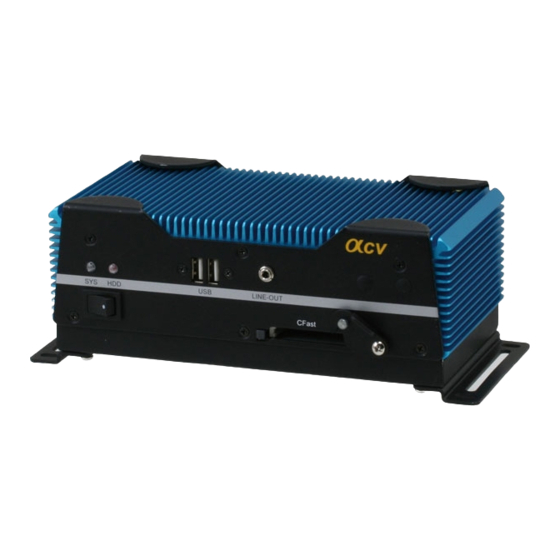
- Page 1 E m b e d d e d C o n t r o l l e r A E C - 6 5 2 3 AEC-6523 Embedded Controller ® Intel Atom™ N2600 Dual Core 1.6GHz Processor Dual LAN, 4 USB2.0, 4 COM, 1 VGA 1 Mini Card AEC-6523 Manual 1 December 2013...
-
Page 2: Copyright Notice
AAEON assumes no liabilities resulting from errors or omissions in this document, or from the use of the information contained herein. AAEON reserves the right to make changes in the product design without notice to its users. - Page 3 E m b e d d e d C o n t r o l l e r A E C - 6 5 2 3 Acknowledgments All other products’ name or trademarks are properties of their respective owners. • AMI is a trademark of American Megatrends, Inc.
-
Page 4: Packing List
A E C - 6 5 2 3 Packing List Before you begin operating your PC, please make sure that the following materials are enclosed: AEC-6523 Embedded Controller Wallmount Brackets Screw Package DVD-ROM for manual (in PDF format) and drivers... - Page 5 E m b e d d e d C o n t r o l l e r A E C - 6 5 2 3 Safety & Warranty 1. Read these safety instructions carefully. 2. Keep this user's manual for later reference. 3.
- Page 6 E m b e d d e d C o n t r o l l e r A E C - 6 5 2 3 The equipment does not work well, or you cannot get it to work according to the user’s manual. The equipment has been dropped and damaged.
- Page 7 E m b e d d e d C o n t r o l l e r A E C - 6 5 2 3 Below Table for China RoHS Requirements 产品中有毒有害物质或元素名称及含量 AAEON Boxer/ Industrial System 有毒有害物质或元素 部件名称 铅...
-
Page 8: Table Of Contents
1.2 Features ..............1-3 1.3 Specifications ............1-4 Chapter 2 Hardware Installation 2.1 Dimension and I/O of AEC-6523....... 2-2 2.2 Connectors and Jumpers of The Main Board ... 2-3 2.3 List of Jumpers ............2-5 2.4 List of Connectors ............. 2-6 2.5 Auto Power Button Selection (JP1)...... - Page 9 E m b e d d e d C o n t r o l l e r A E C - 6 5 2 3 Chapter 4 Driver Installation 4.1 Installation ..............4-3 Appendix A Programming The Watchdog Timer A.1 Programming ............A-2 A.2 ITE8783 Watchdog Timer Initial Program ....A-6 Appendix B I/O Information...
-
Page 10: Chapter 1 General Information
E m b e d d e d C o n t r o l l e r A E C - 6 5 2 3 Chapter General Information 1- 1 Chapter 1 General Information... -
Page 11: Introduction
E m b e d d e d C o n t r o l l e r A E C - 6 5 2 3 1.1 Introduction AAEON introduces the newest product in the Boxer series, ® AEC-6523, which utilizes the Intel Atom™... -
Page 12: Features
E m b e d d e d C o n t r o l l e r A E C - 6 5 2 3 1.2 Features ® Intel Atom N2600 Dual Core 1.6GHz Processor Intel NM10 Express chipset ®... -
Page 13: Specifications
E m b e d d e d C o n t r o l l e r A E C - 6 5 2 3 1.3 Specifications System ® Intel AtomTM N2600 Dual Core 1.6GHz Processor Memory DDR3 SODIMM x 1, supports DDR3 800/1066, Max. - Page 14 E m b e d d e d C o n t r o l l e r A E C - 6 5 2 3 Mechanical and Environmental Construction Rugged Aluminum Alloy Chassis Color Dark Gray Mounting Wall mount/VESA/DIN Rail Dimension 8.35”(W) x 3.1”(H) x 2.25”(D) (212.15 mm x 78.88 mm x 107 mm)
- Page 15 E m b e d d e d C o n t r o l l e r A E C - 6 5 2 3 CE/FCC Class A 1- 6 Chapter 1 General Information...
-
Page 16: Chapter 2 Hardware Installation
E m b e d d e d C o n t r o l l e r A E C - 6 5 2 3 apter Hardware Installation Chapter 2 Hardware Installation... -
Page 17: Dimension And I/O Of Aec-6523
E m b e d d e d C o n t r o l l e r A E C - 6 5 2 3 2.1 Dimension and I/O of AEC-6523 CFast 2 - 2 Chapter 2 Hardware Installation... -
Page 18: Connectors And Jumpers Of The Main Board
E m b e d d e d C o n t r o l l e r A E C - 6 5 2 3 2.2 Connectors and Jumpers of The Main Board Component Side 2 - 3 Chapter 2 Hardware Installation... -
Page 19: Solder Side
E m b e d d e d C o n t r o l l e r A E C - 6 5 2 3 Solder Side 2 - 4 Chapter 2 Hardware Installation... -
Page 20: List Of Jumpers
E m b e d d e d C o n t r o l l e r A E C - 6 5 2 3 2.3 List of Jumpers The board has a number of jumpers that allow you to configure your system to suit your application. -
Page 21: List Of Connectors
E m b e d d e d C o n t r o l l e r A E C - 6 5 2 3 2.4 List of Connectors The board has a number of connectors that allow you to configure your system to suit your application. - Page 22 E m b e d d e d C o n t r o l l e r A E C - 6 5 2 3 CN25 Stereo-L Channel CN26 1st LVDS Inverter CN27 1st LVDS (Single channel 18/24bit) CN28 2nd RJ-45 Ethernet CN29 1st RJ-45 Ethernet...
-
Page 23: Auto Power Button Selection (Jp1)
E m b e d d e d C o n t r o l l e r A E C - 6 5 2 3 2.5 Auto Power Button Selection (JP1) Function Enable Disable (Default) 2.6 Clear CMOS (JP2) Function Normal (Default) Clear CMOS... -
Page 24: Com Port 3 Connector
E m b e d d e d C o n t r o l l e r A E C - 6 5 2 3 RS-232 Mode Signal Signal DCDB DTRB Ground DSRB RTSB CTSB RIB/+5V/(+12V) RS-422 Mode Signal Signal TXD- RXD+... -
Page 25: Com Port 4 Connector
E m b e d d e d C o n t r o l l e r A E C - 6 5 2 3 2.11 COM Port 4 Connector Signal Signal DCDD DTRD Ground DSRD RTSD CTSD 2 - 10 Chapter 2 Hardware Installation... -
Page 26: Hard Disk Drive Installation
E m b e d d e d C o n t r o l l e r A E C - 6 5 2 3 2.12 Hard Disk Drive Installation Step 1: Open the bottom case of AEC-6523 by loosening the two screws. Step 2: Get the Hard Disk Drive ready. 2 - 11... - Page 27 E m b e d d e d C o n t r o l l e r A E C - 6 5 2 3 Step 3: Install the CFast™ card. Step 4: Fasten the cover of the CFast™ card. 2 - 12 Chapter 2 Hardware Installation...
- Page 28 E m b e d d e d C o n t r o l l e r A E C - 6 5 2 3 Step 5: Stack the HDD and bracket. Fasten the HDD and bracket with the screws.
- Page 29 E m b e d d e d C o n t r o l l e r A E C - 6 5 2 3 Step 7: Fasten the bracket of the HDD. Step 8: Fasten the bottom HDD kit case of AEC-6523. 2 - 14 Chapter 2 Hardware Installation...
-
Page 30: Sd Ram Installation
E m b e d d e d C o n t r o l l e r A E C - 6 5 2 3 2.13 SD RAM Installation Loosen the bottom HDD kit of the AEC-6523. Step 1: Step 2: Fasten the bottom case of the AEC-6523. 2 - 15 Chapter 2 Hardware Installation... - Page 31 E m b e d d e d C o n t r o l l e r A E C - 6 5 2 3 Step 3: Loosen the screw on the front panel of AEC-6523 Step 4: Loosen the screws on the rear panel of AEC-6523...
- Page 32 E m b e d d e d C o n t r o l l e r A E C - 6 5 2 3 Step 5: Insert the SDRAM to the memory slot. Step 6: Press the SDRAM and make sure that it has been inserted properly. 2 - 17 Chapter 2 Hardware Installation...
- Page 33 E m b e d d e d C o n t r o l l e r A E C - 6 5 2 3 Step 7: Adhere the heat-spreading sheet to the SDRAM. Step 8: Close the bottom case of AEC-6523 and fasten the four screws on the bottom case. 2 - 18...
- Page 34 A E C - 6 5 2 3 Step 8-1: Close the bottom HDD kit case of AEC-6523 and fasten the two screws on the bottom case. Step 9: Close the front case of AEC-6523 and fasten the screw on the front case. 2 - 19...
- Page 35 E m b e d d e d C o n t r o l l e r A E C - 6 5 2 3 Step 10: Close the rear case of AEC-6523 and fasten the two screws on the rear case.
-
Page 36: Din Rail Installation
E m b e d d e d C o n t r o l l e r A E C - 6 5 2 3 2.14 DIN Rail Installation Step 1: Fix the DIN Rail kit with the screws on the chassis as shown below. Step 2: Press the DIN Rail on the DIN Rail kit to fix it. -
Page 37: Wallmount Installation
E m b e d d e d C o n t r o l l e r A E C - 6 5 2 3 2.15 Wallmount Installation Step 1: Fasten the brackets with the screws. We suggest using this screw. 2 - 22 Chapter 2 Hardware Installation... -
Page 38: Bios Setup
E m b e d d e d C o n t r o l l e r A E C - 6 5 2 3 Chapter BIOS Setup Chapter 3 Award BIOS Setup 3-1... -
Page 39: Chapter 3 Ami Bios Setup
2. You have changed the hardware attached to your system 3. The CMOS memory has lost power and the configuration information has been erased. The AEC-6523 CMOS memory has an integral lithium battery backup for data retention. You have to replace the battery when it finally runs down. -
Page 40: Ami Bios Setup
S u b C o m p a c t B o a r d A E C - 6 5 2 3 3.2 AMI BIOS Setup AMI BIOS ROM has a built-in Setup program that allows users to modify the basic system configuration. This type of information is stored in battery-backed CMOS RAM so that it retains the Setup information when the power is turned off. - Page 41 S u b C o m p a c t B o a r d A E C - 6 5 2 3 Setup submenu: Main Options summary: (default setting) System Date Day MM:DD:YYYY Change the month, year and century. The ‘Day’ is changed automatically. System Time HH : MM : SS Change the clock of the system.
- Page 42 S u b C o m p a c t B o a r d A E C - 6 5 2 3 Setup submenu: Advanced Options summary: (default setting) ACPI Settings System ACPI Parameters S5 RTC Wake Settings Enable system to wake from S5 using RTC alarm. CPU Configuration CPU Configuration Parameters SATA Configuration...
- Page 43 S u b C o m p a c t B o a r d A E C - 6 5 2 3 USB Configuration Parameters Super IO Configuration System Super IO Chip Parameters H/W Monitor Monitor hardware status Chapter 3 AMI BIOS Setup 3-6...
-
Page 44: Acpi Settings
S u b C o m p a c t B o a r d A E C - 6 5 2 3 ACPI Settings Options summary: (default setting) Suspend Disabled ACPI Sleep State S1 only(CPU Stop Clock) S3 only(Suspend to RAM) Select the ACPI state used for System Suspend Chapter 3 Award BIOS Setup 3-7... -
Page 45: Rtc Wake Settings
S u b C o m p a c t B o a r d A E C - 6 5 2 3 RTC Wake Settings Options summary: (default setting) Wake system with Fixed Disabled Time Enabled Enable or disable System wake on alarm event. Wake up time is setting by following settings. - Page 46 S u b C o m p a c t B o a r d A E C - 6 5 2 3 Wake system with Disabled Dynamic Time Enabled Enable or disable System wake on alarm event. Wake up time is current time + Increase minutes.
-
Page 47: Cpu Configuration
S u b C o m p a c t B o a r d A E C - 6 5 2 3 CPU Configuration Options summary: (default setting) Hyper-Threading Disabled Enabled En/Disable CPU Hyper-Threading function Chapter 3 AMI BIOS Setup 3-10... - Page 48 S u b C o m p a c t B o a r d A E C - 6 5 2 3 SATA Configuration Options summary: (default setting) SATA Controller(s) Disabled Enabled En/Disable SATA controller Configure SATA as AHCI Configure SATA controller operating as IDE/AHCI mode.
- Page 49 S u b C o m p a c t B o a r d A E C - 6 5 2 3 SATA Configuration AHCI Options summary: (default setting) SATA Controller(s) Disabled Enabled En/Disable SATA controller Configure SATA as AHCI Configure SATA controller operating as IDE/AHCI mode.
- Page 50 S u b C o m p a c t B o a r d A E C - 6 5 2 3 En/Disable the selected port. SATA Port 0/Port 1 Hot Plug Disabled Enabled En/Disable Hot Plug feature for specified port. Chapter 3 Award BIOS Setup 3-13...
-
Page 51: Usb Configuration
S u b C o m p a c t B o a r d A E C - 6 5 2 3 USB Configuration Options summary: (default setting) Legacy USB Support Enabled Disabled Auto Enables BIOS Support for Legacy USB Support. When enabled, USB can be functional in legacy environment like DOS. - Page 52 S u b C o m p a c t B o a r d A E C - 6 5 2 3 Forced FDD Hard Disk CD-ROM If Auto. USB devices less than 530MB will be emulated as Floppy and remaining as Floppy and remaining as hard drive.
-
Page 53: Super Io Configuration
S u b C o m p a c t B o a r d A E C - 6 5 2 3 Super IO Configuration Options summary: (default setting) Serial Port 1/2/3/4 Configuration Set Parameters of Serial Port 1/2/3/4 Restore AC Power Loss Power Off Power On... -
Page 54: Serial Port 1 Configuration
S u b C o m p a c t B o a r d A E C - 6 5 2 3 Serial Port 1 Configuration Options summary: (default setting) Serial Port Disabled Enabled En/Disable specified serial port. Change Settings Auto IO=3F8h;... -
Page 55: Serial Port 2 Configuration
S u b C o m p a c t B o a r d A E C - 6 5 2 3 Serial Port 2 Configuration Options summary: (default setting) Serial Port Disabled Enabled En/Disable specified serial port. Change Settings Auto IO=2F8h;... - Page 56 S u b C o m p a c t B o a r d A E C - 6 5 2 3 Select a resource setting for Super IO device. COM2 Type Select RS232 RS422 RS485 Configure COM2 operated as RS232, RS422 or RS485. Chapter 3 Award BIOS Setup 3-19...
-
Page 57: Serial Port 3 Configuration
S u b C o m p a c t B o a r d A E C - 6 5 2 3 Serial Port 3 Configuration Options summary: (default setting) Serial Port Disabled Enabled En/Disable specified serial port. Change Settings Auto IO=3E8h;... - Page 58 S u b C o m p a c t B o a r d A E C - 6 5 2 3 Serial Port 4 Configuration Options summary: (default setting) Serial Port Disabled Enabled En/Disable specified serial port. Change Settings Auto IO=2E8h;...
- Page 59 S u b C o m p a c t B o a r d A E C - 6 5 2 3 H/W Monitor Chapter 3 AMI BIOS Setup 3-22...
- Page 60 S u b C o m p a c t B o a r d A E C - 6 5 2 3 Setup submenu: Chipset Options summary: (default setting) Host Bridge Host Bridge Parameters South Bridge South Bridge Parameters Chapter 3 Award BIOS Setup 3-23...
-
Page 61: Host Bridge
S u b C o m p a c t B o a r d A E C - 6 5 2 3 Host Bridge Options summary: (default setting) Intel IGD Configuration Configure Intel IGD Settings. Chapter 3 AMI BIOS Setup 3-24... -
Page 62: Intel Igd Configuration
S u b C o m p a c t B o a r d A E C - 6 5 2 3 Intel IGD Configuration Options summary: (default setting) Auto Disable IGD Enabled Disabled Select Primary boot display device IGFX –... -
Page 63: South Bridge
S u b C o m p a c t B o a r d A E C - 6 5 2 3 South Bridge Options summary: (default setting) Power Mode ATX Type AT Type Select the power type used on the system TPT Devices HD audio and onboard LAN Settings. -
Page 64: Tpt Devices
S u b C o m p a c t B o a r d A E C - 6 5 2 3 TPT Devices Options summary: (default setting) Azalia Controller Disabled HD Audio Enable or disabled Azalia controller R8111E #1 Controller Disabled Enabled Enable or disable PCIE Lan. - Page 65 S u b C o m p a c t B o a r d A E C - 6 5 2 3 Setup submenu: Boot Options summary: (default setting) Quiet Boot Disabled Enabled En/Disable showing boot logo. Launch RTL8111E PXE Disabled OpROM Enabled...
- Page 66 S u b C o m p a c t B o a r d A E C - 6 5 2 3 BBS Priorities Options summary: (default setting) Boot Option #x Disabled Device name Sets the system boot order Chapter 3 Award BIOS Setup 3-29...
- Page 67 S u b C o m p a c t B o a r d A E C - 6 5 2 3 Setup submenu: Security Options summary: (default setting) Administrator Password/ Not set User Password Chapter 3 AMI BIOS Setup 3-30...
- Page 68 S u b C o m p a c t B o a r d A E C - 6 5 2 3 You can install a Supervisor password, and if you install a supervisor password, you can then install a user password. A user password does not provide access to many of the features in the Setup utility.
- Page 69 S u b C o m p a c t B o a r d A E C - 6 5 2 3 HDD Security Options summary: (default setting) Set User Password/ Not set Set Master Password Chapter 3 AMI BIOS Setup 3-32...
- Page 70 S u b C o m p a c t B o a r d A E C - 6 5 2 3 You can install a Master and User password. Before booting to OS, HDD will be set to frozen state. On S3 resume HDD will be unlocked using the HDD Password we entered while system booting.
- Page 71 S u b C o m p a c t B o a r d A E C - 6 5 2 3 Setup submenu: Exit Options summary: (default setting) Save Changes and Reset Reset the system after saving the changes Discard Changes and Reset Reset system setup without saving any changes Restore Defaults...
- Page 72 E m b e d d e d C o n t r o l l e r A E C - 6 5 2 3 Chapter Driver Installation 4 - 1 Chapter 4 Driver Installation...
- Page 73 E m b e d d e d C o n t r o l l e r A E C - 6 5 2 3 The AEC-6523 comes with a DVD-ROM that contains all drivers and utilities that meet your needs.
- Page 74 E m b e d d e d C o n t r o l l e r A E C - 6 5 2 3 4.1 Installation: Insert the AEC-6523 DVD-ROM into the DVD-ROM drive, and then install the drivers from Step 1 to Step 6 in order. Step 1 – Install Chipset Driver 1.
- Page 75 E m b e d d e d C o n t r o l l e r A E C - 6 5 2 3 Step 3 – Install LAN Driver 1. Click on the STEP3-LAN folder and select the OS folder your system is 2.
- Page 76 E m b e d d e d C o n t r o l l e r A E C - 6 5 2 3 located in each OS folder 3. Follow the instructions that the window shows 4. The system will help you install the driver automatically Note: If the OS is Chinese version, you may click on Serial Patch v1.0.1.
-
Page 77: Watchdog Timer
E m b e d d e d C o n t r o l l e r A E C - 6 5 2 3 Appendix Programming the Watchdog Timer Appendix A Programming the Watchdog Timer A-1... -
Page 78: A.1 Programming
E m b e d d e d C o n t r o l l e r A E C - 6 5 2 3 A.1 Programming AEC-6523 utilizes the ITE 8783 chipset as its watchdog timer controller. Below are the procedures to complete its configuration and the AAEON initial watchdog timer program is also attached based on which you can develop customized program to fit your application. - Page 79 E m b e d d e d C o n t r o l l e r A E C - 6 5 2 3 Exit the MB PnP Mode. Undesired result may occur if the MB PnP Mode is not exited normally. (1) Enter the MB PnP Mode To enter the MB PnP Mode, four special I/O write operations are to be performed during Wait for Key state.
- Page 80 E m b e d d e d C o n t r o l l e r A E C - 6 5 2 3 Configure Control (Index=02h) This register is write only. Its values are not sticky; that is to say, a hardware reset will automatically clear the bits, and does not require the software to clear them.
- Page 81 E m b e d d e d C o n t r o l l e r A E C - 6 5 2 3 82h, 92h Default=001s0000b) Watch Dog Timer 1,2,3 Time-Out Value (LSB) Register (Index=73h,83h,93h, Default=38h) Watch Dog Timer 1,2,3 Time-Out Value (MSB) Register (Index=74h,84h,94h Default=00h) Appendix A Programming the Watchdog Timer A-5...
-
Page 82: A.2 Ite8783 Watchdog Timer Initial Program
E m b e d d e d C o n t r o l l e r A E C - 6 5 2 3 A.2 ITE8783 Watchdog Timer Initial Program .MODEL SMALL .CODE Main: CALL Enter_Configuration_mode CALL Check_Chip mov cl, 7 call Set_Logic_Device ;time setting... - Page 83 E m b e d d e d C o n t r o l l e r A E C - 6 5 2 3 call Superio_Set_Reg ; game port enable mov cl, 9 call Set_Logic_Device Initial_OK: CALL Exit_Configuration_mode MOV AH,4Ch INT 21h Enter_Configuration_Mode PROC NEAR...
- Page 84 E m b e d d e d C o n t r o l l e r A E C - 6 5 2 3 CALL Write_Configuration_Data Exit_Configuration_Mode ENDP Check_Chip PROC NEAR MOV AL,20h CALL Read_Configuration_Data CMP AL,87h JNE Not_Initial MOV AL,21h CALL Read_Configuration_Data CMP AL,81h...
- Page 85 E m b e d d e d C o n t r o l l e r A E C - 6 5 2 3 OUT DX,AL MOV DX,WORD PTR CS:[Cfg_Port+06h] IN AL,DX Read_Configuration_Data ENDP Write_Configuration_Data PROC NEAR MOV DX,WORD PTR CS:[Cfg_Port+04h] OUT DX,AL XCHG AL,AH MOV DX,WORD PTR CS:[Cfg_Port+06h]...
- Page 86 E m b e d d e d C o n t r o l l e r A E C - 6 5 2 3 Set_Logic_Device proc near push ax push cx xchg al,cl mov cl,07h call Superio_Set_Reg pop cx pop ax Set_Logic_Device endp ;Select 02Eh->Index Port, 02Fh->Data Port...
- Page 87 E m b e d d e d C o n t r o l l e r A E C - 6 5 2 3 Appendix I/O Information B - 1 Appendix B I/O Information...
-
Page 88: B.1 I/O Address Map
E m b e d d e d C o n t r o l l e r A E C - 6 5 2 3 B.1 I/O Address Map B - 2 Appendix B I/O Information... - Page 89 E m b e d d e d C o n t r o l l e r A E C - 6 5 2 3 B - 3 Appendix B I/O Information...
- Page 90 E m b e d d e d C o n t r o l l e r A E C - 6 5 2 3 B.2 1 MB Memory Address Map B - 4 Appendix B I/O Information...
-
Page 91: B.3 Irq Mapping Chart
E m b e d d e d C o n t r o l l e r A E C - 6 5 2 3 B.3 IRQ Mapping Chart B - 5 Appendix B I/O Information... -
Page 92: B.4 Dma Channel Assignments
E m b e d d e d C o n t r o l l e r A E C - 6 5 2 3 B.4 DMA Channel Assignments B - 6 Appendix B I/O Information... - Page 93 E m b e d d e d C o n t r o l l e r A E C - 6 5 2 3 A ppendix AHCI Setting Appendix C AHCI Setting...
-
Page 94: C.1 Setting Ahci
E m b e d d e d C o n t r o l l e r A E C - 6 5 2 3 C.1 Setting AHCI OS installation to setup AHCI Mode. Step 1: Copy the files below from “Driver CD -> STEP5-AHCI\WINXP_32\F6 Install Floppy for Windows”... - Page 95 E m b e d d e d C o n t r o l l e r A E C - 6 5 2 3 Step 3: Press “F6” Step 4: Choose “S” Appendix C AHCI Setting...
- Page 96 E m b e d d e d C o n t r o l l e r A E C - 6 5 2 3 Step 5: Choose “Intel® NM10 Express Chipset” Step 6: It will show the model number you select and then press “ENTER Step 7: Setup is loading files Appendix C AHCI Setting...
Need help?
Do you have a question about the AEC-6523 and is the answer not in the manual?
Questions and answers