
Related Manuals for Aaeon AHP-2176


Summary of Contents for Aaeon AHP-2176
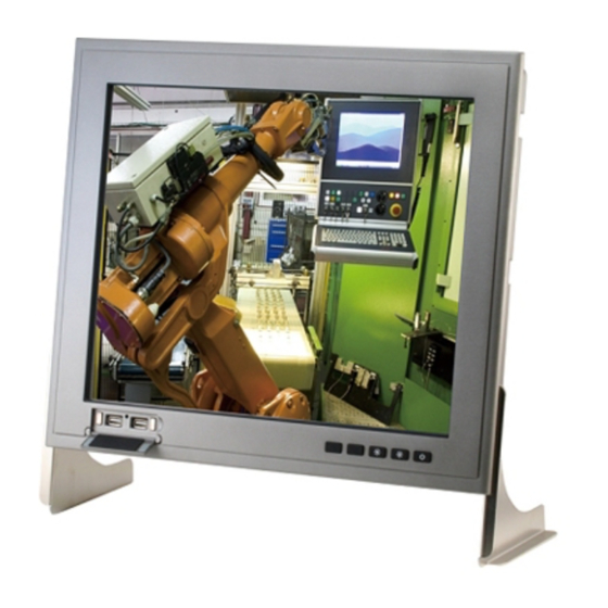
- Page 1 T o u c h P a n e l P C A H P - 2 1 7 6 AHP-2176 ® ® Onboard Intel Celeron 827E 1.4GHz Processor Touch Panel PC With 17” TFT LCD AHP-2176 Manual 3rd Ed. April 30, 2014...
- Page 2 AAEON assumes no liabilities resulting from errors or omissions in this document, or from the use of the information contained herein. AAEON reserves the right to make changes in the product design without notice to its users.
- Page 3 T o u c h P a n e l P C A H P - 2 1 7 6 Acknowledgments All other products’ name or trademarks are properties of their respective owners. AMI is a trademark of American Megatrends Inc. ...
- Page 4 A H P - 2 1 7 6 Packing List Before you begin operating your PC, please make sure that the following materials are enclosed: AHP-2176 Touch Panel PC Mounting brackets and screws DVD-ROM for manual (in PDF format) and drivers If any of these items should be missing or damaged, please contact your distributor or sales representative immediately.
- Page 5 T o u c h P a n e l P C A H P - 2 1 7 6 Safety & Warranty 1. Read these safety instructions carefully. 2. Keep this user's manual for later reference. 3. Disconnect this equipment from any AC outlet before cleaning. Do not use liquid or spray detergents for cleaning.
- Page 6 T o u c h P a n e l P C A H P - 2 1 7 6 The equipment does not work well, or you cannot get it to work according to the user’s manual. The equipment has been dropped and damaged. The equipment has obvious signs of breakage.
- Page 7 T o u c h P a n e l P C A H P - 2 1 7 6 This device complies with Part 15 FCC Rules. Operation is subject to the following two conditions: (1) this device may not cause harmful interference, and (2) this device must accept any interference received including interference that may cause undesired...
- Page 8 T o u c h P a n e l P C A H P - 2 1 7 6 Below Table for China RoHS Requirements 产品中有毒有害物质或元素名称及含量 AAEON Panel PC/ Workstation 有毒有害物质或元素 部件名称 铅 汞 镉 六价铬 多溴联苯 多溴二苯醚 (Pb)
-
Page 9: Table Of Contents
T o u c h P a n e l P C A H P - 2 1 7 6 Contents Chapter 1 General Information 1.1 Introduction ..............1-2 1.2 Specification .............. 1-3 1.3 Dimension ..............1-6 Chapter 2 Hardware Installation 2.1 Panelmount Installation .......... -
Page 10: Chapter 1 General Information
T o u c h P a n e l P C A H P - 2 1 7 6 Chapter General Information 1- 1 Chapter 1 General Information... -
Page 11: Introduction
TFT LCD display, onboard Ethernet controller, multi-COM port interfaces and an audio controller. With a built-in CFast™ socket, the AHP-2176 is as compact and user friendly as a multi-function computer. In addition, its "fit anywhere" design makes it very flexible and able to be used in many different kinds of installations. -
Page 12: Specification
T o u c h P a n e l P C A H P - 2 1 7 6 1.2 Specification System ® ® Onboard Intel Celeron 827E 1.4GHz Processor System Memory DDR3 800/1066/1333 MHz (204 pin) x 2, SODIMM, Max. - Page 13 T o u c h P a n e l P C A H P - 2 1 7 6 Dimension 16.5”(W) x 14.1”(H) x 2.8”(D) (420mm x 358mm x 97mm) Carton Dimension 26”(W) x 8.11”(H) x 19.53”(D) (661mm x 206mm x 496mm) ...
- Page 14 T o u c h P a n e l P C A H P - 2 1 7 6 Display Type 17” TFT LCD Max. Resolution 1280x1024 Max. Colors 16.7M colors Luminance (cd/m HTT : 350 ...
-
Page 15: Dimension
T o u c h P a n e l P C A H P - 2 1 7 6 1.3 Dimension AHP- 2 1 7 6 UNITS: m m 9 7 . 3 0 4 1 9 . 7 6 3 4 . -
Page 16: Chapter 2 Hardware Installation
T o u c h P a n e l P C A H P - 2 1 7 6 Chapter Hardware Installation Chapter 2 Quick Installation Guide... -
Page 17: Panelmount Installation
T o u c h P a n e l P C A H P - 2 1 7 6 2.1 Panelmount Installation The display panel can be mounted into the wall. You will need the screws along with the mounting brackets, which be packed in the accessory box. - Page 18 T o u c h P a n e l P C A H P - 2 1 7 6 Complete Illustration 2 - 3 Chapter 2 Quick Installation Guide...
- Page 19 T o u c h P a n e l P C A H P - 2 1 7 6 2.2 COM Port Connector S ignal S ignal 2 - 4 Chapter 2 Quick Installation Guide...
-
Page 20: Hard Disk Drive Installation
T o u c h P a n e l P C A H P - 2 1 7 6 2.3 Hard Disk Drive Installation Step 1: Unfasten the screws of the heatsink Step 2: Get the Bracket of Hard Disk Drive from the package 2 - 5 Chapter 2 Quick Installation Guide... - Page 21 T o u c h P a n e l P C A H P - 2 1 7 6 Step 3: Fasten the Hard Disk onto the bracket 2 - 6 Chapter 2 Quick Installation Guide...
- Page 22 T o u c h P a n e l P C A H P - 2 1 7 6 Step 4: Fasten the screws of the hard disk bracket onto the AHP-2176 2 - 7 Chapter 2 Quick Installation Guide...
- Page 23 T o u c h P a n e l P C A H P - 2 1 7 6 Chapter BIOS Setup Chapter 3 AMI BIOS Setup 3-1...
-
Page 24: System Test And Initialization
4. The CMOS memory has lost power and the configuration information has been erased. The AHP-2176 CMOS memory has an integral lithium battery backup for data retention. However, you will need to replace the complete unit when it finally runs down. -
Page 25: Ami Bios Setup
T o u c h P a n e l P C A H P - 2 1 7 6 3.2 AMI BIOS Setup AMI BIOS ROM has a built-in Setup program that allows users to modify the basic system configuration. This type of information is stored in battery-backed CMOS RAM and BIOS NVRAM so that it retains the Setup information when the power is turned off. - Page 26 T o u c h P a n e l P C A H P - 2 1 7 6 Setup Menu Setup submenu: Main Chapter 3 AMI BIOS Setup 3-4...
- Page 27 T o u c h P a n e l P C A H P - 2 1 7 6 Setup submenu: Advanced Chapter 3 AMI BIOS Setup 3-5...
- Page 28 T o u c h P a n e l P C A H P - 2 1 7 6 ACPI Settings Options Summary : ACPI Sleep State Suspend Disabled S1 (CPU Stop Clock) S3 (Suspend to RAM) Default Select the Highest ACPI sleep state the system will enter when the SUSPEND button is pressed.
- Page 29 T o u c h P a n e l P C A H P - 2 1 7 6 Trusted Computing Option Summary : TPM SUPPORT Disable Default Enable Enables or Disables TPM support. O.S. will not show TPM. Reset of platform is required.
- Page 30 T o u c h P a n e l P C A H P - 2 1 7 6 CPU Configuration Options Summary : Intel Disabled Virtualization Enabled Default Technology When enabled, a VMM can utilize the additional hardware capabilities provided by Vanderpool Technology Chapter 3 AMI BIOS Setup 3-8...
- Page 31 T o u c h P a n e l P C A H P - 2 1 7 6 SATA Configuration (IDE) Options Summary : SATA Enabled Default Controller(s) Disabled Enable or disable SATA Device. SATA Mode Default Selection AHCI RAID Determines how SATA controller(s) operate.
- Page 32 T o u c h P a n e l P C A H P - 2 1 7 6 IDE Configuration (AHCI) Options Summary : SATA Controller(s) Disabled Enabled Default Enable or Disable SATA Port. SATA Mode Selection AHCI Selected RAID Determines how SATA controller(s) operate.
- Page 33 T o u c h P a n e l P C A H P - 2 1 7 6 SATA Port 3 Hot Plug Disable Default Enabled Designates this port as Hot Pluggable. SATA Port 4 Hot Plug Disable Default Enabled Designates this port as Hot Pluggable.
- Page 34 T o u c h P a n e l P C A H P - 2 1 7 6 IDE Configuration (RAID) Options Summary : SATA Controller(s) Disabled Enabled Default Enable or Disable SATA Port. SATA Mode AHCI RAID Selected Determines how SATA controller(s) operate.
- Page 35 T o u c h P a n e l P C A H P - 2 1 7 6 SATA Port 3 Hot Plug Disable Default Enabled Designates this port as Hot Pluggable. SATA Port 4 Hot Plug Disable Default Enabled Designates this port as Hot Pluggable.
- Page 36 T o u c h P a n e l P C A H P - 2 1 7 6 PCH-FW Configuration Options Summary : Firmware Configure Management Engine Technology Parameters. Update Configuration Chapter 3 AMI BIOS Setup 3-14...
- Page 37 T o u c h P a n e l P C A H P - 2 1 7 6 Firmware Update Configuration Options Summary : Me FW Image Disabled Default Re-Flash Enabled Enable/Disable Me FW Image Re-Flash function. Chapter 3 AMI BIOS Setup 3-15...
- Page 38 T o u c h P a n e l P C A H P - 2 1 7 6 USB Configuration Options Summary : Legacy USB Support Enabled Default Disabled Auto Enable Legacy USB support. AUTO option disables legacy support if no USB devices are connected. DISABLE option will keep USB devices available only for EFI applications.
- Page 39 T o u c h P a n e l P C A H P - 2 1 7 6 Super IO Configuration Options Summary : Serial Port 3 Set Parameters of Serial Port 3 (COMC) Configuration Serial Port 4 Set Parameters of Serial Port 4 (COMD) Configuration Serial Port 5...
- Page 40 T o u c h P a n e l P C A H P - 2 1 7 6 Serial Port 3 Configuration Options Summary : Serial Port Enabled Default Disabled Enable or Disable Serial Port (COM) Change Settings Auto Default IO=3E8h;...
- Page 41 T o u c h P a n e l P C A H P - 2 1 7 6 Serial Port 4 Configuration Options Summary : Serial Port Enabled Default Disabled Enable or Disable Serial Port (COM) Change Settings Auto Default IO=2E8h;...
- Page 42 T o u c h P a n e l P C A H P - 2 1 7 6 Serial Port 5 Configuration Options Summary : Serial Port Enabled Default Disabled Enable or Disable Serial Port (COM) Change Settings Auto Default IO=2D0h;...
- Page 43 T o u c h P a n e l P C A H P - 2 1 7 6 Serial Port 6 Configuration Options Summary : Serial Port Enabled Default Disabled Enable or Disable Serial Port (COM) Change Settings Auto Default IO=2D8h;...
- Page 44 T o u c h P a n e l P C A H P - 2 1 7 6 H/W Monitor Chapter 3 AMI BIOS Setup 3-22...
- Page 45 T o u c h P a n e l P C A H P - 2 1 7 6 Setup submenu: Chipset Chapter 3 AMI BIOS Setup 3-23...
- Page 46 T o u c h P a n e l P C A H P - 2 1 7 6 System Agent (SA) Configuration Options Summary : Graphics Config Graphics Settings. Configuration Chapter 3 AMI BIOS Setup 3-24...
- Page 47 T o u c h P a n e l P C A H P - 2 1 7 6 Graphics Configuration Options Summary : Internal Graphics Auto Default Disabled Enabled Keep IGD enabled based on the setup options. DVMT Pre-Allocated Default 128M 160M...
- Page 48 T o u c h P a n e l P C A H P - 2 1 7 6 384M 416M 448M 480M 512M Select DVMT 5.0 Pre-Allocated (Fixed) Graphics Memory size used by the Internal Graphics Device. DVMT Total Gfx Men 128M 256M Default...
- Page 49 T o u c h P a n e l P C A H P - 2 1 7 6 Display Control Options Summary : Boot Display Select VBIOS Default Default LVDS CRT+LVDS Select the Video Device during POST and DOS. This has no effect if external graphics present.
- Page 50 T o u c h P a n e l P C A H P - 2 1 7 6 1680x1050 1280x800 1920x1080 Select LCD panel used by Internal Graphics Device by selecting the appropriate setup items. Panel Color Depth 18 bit 24 bit Select the LFP Panel Color Depth...
- Page 51 T o u c h P a n e l P C A H P - 2 1 7 6 PCH-IO Configuration Options Summary : Power Mode ATX Type Default AT Type Select power supply mode. Restore AC Power Power off Loss Power on Last State...
- Page 52 T o u c h P a n e l P C A H P - 2 1 7 6 Enable or disable internal HDMI codec for Azalia. Azalia HDMI codec Disabled Default Port B Enabled Enable or disable internal HDMI codec Port for Azalia. Azalia HDMI codec Disabled Port C...
- Page 53 T o u c h P a n e l P C A H P - 2 1 7 6 Setup submenu: Boot Options Summary : Quiet Boot Disabled Enabled Default Enables or disables Quiet Boot option Launch I82579LM PXE Disabled Default OpROM...
- Page 54 T o u c h P a n e l P C A H P - 2 1 7 6 Hard Drives BBS Priorities Chapter 3 AMI BIOS Setup 3-32...
- Page 55 T o u c h P a n e l P C A H P - 2 1 7 6 Submenu: Security Change User/Supervisor Password You can install a Supervisor password, and if you install a supervisor password, you can then install a user password. A user password does not provide access to many of the features in the Setup utility.
- Page 56 T o u c h P a n e l P C A H P - 2 1 7 6 Setup submenu: Exit Chapter 3 AMI BIOS Setup 3-34...
-
Page 57: Chapter 4 Driver Installation
T o u c h P a n e l P C A H P - 2 1 7 6 Chapter Driver Installation 4 -1 Chapter 4 Driver Installation... - Page 58 T o u c h P a n e l P C A H P - 2 1 7 6 The AHP-2176 comes with an AutoRun DVD-ROM that contains all drivers and utilities that can help you to install the driver automatically.
- Page 59 T o u c h P a n e l P C A H P - 2 1 7 6 4.1 Installation: Insert the AHP-2176 DVD-ROM into the DVD-ROM drive. And install the drivers from Step 1 to Step 8 in order. Step 1 – Install Chipset Driver 1.
- Page 60 T o u c h P a n e l P C A H P - 2 1 7 6 dotNet Framwork folder. Step 3 –Install Audio Driver 1. Click on the STEP3-AUDIO folder and select the OS folder your system is 2.
- Page 61 T o u c h P a n e l P C A H P - 2 1 7 6 Step 6 – Install TPM Driver 1. Click on the STEP6-TPM folder and double click on the Setup.exe file 2. Follow the instructions that the window shows 3.
- Page 62 T o u c h P a n e l P C A H P - 2 1 7 6 1. Create a password for Administrator account. 2. Change User Account Control Settings to [Never notify] 4 -6 Chapter 4 Driver Installation...
- Page 63 T o u c h P a n e l P C A H P - 2 1 7 6 3. Reboot and Administrator login. 4. To run patch.bat with [Run as administrator]. 4 -7 Chapter 4 Driver Installation...
- Page 64 T o u c h P a n e l P C A H P - 2 1 7 6 4 -8 Chapter 4 Driver Installation...
-
Page 65: Appendix A Programming The Watchdog Timer
T o u c h P a n e l P C A H P - 2 1 7 6 Appendix Programming the Watchdog Timer Appendix A Programming the Watchdog Timer... -
Page 66: Watchdog Timer Initial Program
T o u c h P a n e l P C A H P - 2 1 7 6 A.1 Watchdog Timer Initial Program Table 1 : SuperIO relative register table Default Value Note SIO MB PnP Mode Index Register Index 0x2E(Note1) 0x2E or 0x4E... - Page 67 T o u c h P a n e l P C A H P - 2 1 7 6 ********************************************************************************* // SuperIO relative definition (Please reference to Table 1) #define byte SIOIndex //This parameter is represented from Note1 #define byte SIOData //This parameter is represented from Note2 #define void IOWriteByte(byte IOPort, byte Value);...
- Page 68 T o u c h P a n e l P C A H P - 2 1 7 6 #define byte WDTRstBit // This parameter is represented from Note22 #define byte WDTRstVal // This parameter is represented from Note23 ********************************************************************************* ********************************************************************************* VOID Main(){...
- Page 69 T o u c h P a n e l P C A H P - 2 1 7 6 VOID WDTEnableDisable(byte LDN, byte Register, byte BitNum, byte Value){ SIOBitSet(LDN, Register, BitNum, Value); VOID WDTParameterSetting(){ // Watchdog Timer counter setting SIOByteSet(TimerLDN, TimerReg, TimerVal);...
- Page 70 T o u c h P a n e l P C A H P - 2 1 7 6 VOID SIOBitSet(byte LDN, byte Register, byte BitNum, byte Value){ Byte TmpValue; SIOEnterMBPnPMode(); SIOSelectLDN(byte LDN); IOWriteByte(SIOIndex, Register); TmpValue = IOReadByte(SIOData); TmpValue &= ~(1 << BitNum); TmpValue |= (Value <<...
-
Page 71: Appendix B I/O Information
T o u c h P a n e l P C A H P - 2 1 7 6 Appendix I/O Information B - 1 Appendix B I/O Information... -
Page 72: I/O Address Map
T o u c h P a n e l P C A H P - 2 1 7 6 B.1 I/O Address Map B - 2 Appendix B I/O Information... - Page 73 T o u c h P a n e l P C A H P - 2 1 7 6 B - 3 Appendix B I/O Information...
-
Page 74: Memory Address Map
T o u c h P a n e l P C A H P - 2 1 7 6 B.2 Memory Address Map B - 4 Appendix B I/O Information... -
Page 75: Irq Mapping Chart
T o u c h P a n e l P C A H P - 2 1 7 6 B.3 IRQ Mapping Chart B - 5 Appendix B I/O Information... - Page 76 T o u c h P a n e l P C A H P - 2 1 7 6 B - 6 Appendix B I/O Information...
-
Page 77: Dma Channel Assignments
T o u c h P a n e l P C A H P - 2 1 7 6 B.4 DMA Channel Assignments B - 7 Appendix B I/O Information...
Need help?
Do you have a question about the AHP-2176 and is the answer not in the manual?
Questions and answers