
Related Manuals for Aaeon AIS-E2-CV1


Summary of Contents for Aaeon AIS-E2-CV1
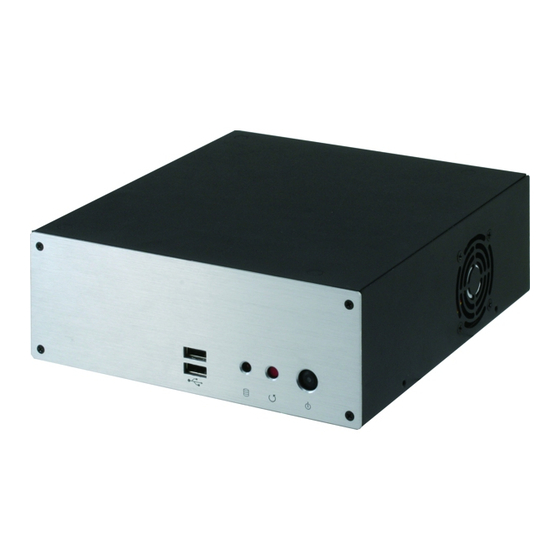
- Page 1 A I S - E 2 - C V 1 C o n t r o l l e r AIS-E2-CV1 Advanced System Controller 2.5” HDD/SSD x 2 Gigabit Ethernet x 2 COM x 6, USB2.0 x 6 HD Audio Codec AIS-E2-CV1 Manual 1st Ed. November 2013...
- Page 2 AAEON assumes no liabilities resulting from errors or omissions in this document, or from the use of the information contained herein. AAEON reserves the right to make changes in the product design without notice to its users.
- Page 3 A d va n c e d S ys t e m A I S - E 2 - C V 1 C o n t r o l l e r Acknowledgments All other products’ name or trademarks are properties of their respective owners.
- Page 4 9761E20000 Gift Box (Including 84W Power adapter, CPU Cooler) DVD-ROM for manual (in PDF format) and drivers AIS-E2-CV1 If any of these items should be missing or damaged, please contact your distributor or sales representative immediately.
- Page 5 A d va n c e d S ys t e m A I S - E 2 - C V 1 C o n t r o l l e r Safety & Warranty 1. Read these safety instructions carefully. 2.
- Page 6 A d va n c e d S ys t e m A I S - E 2 - C V 1 C o n t r o l l e r The equipment does not work well, or you cannot get it to work according to the user’s manual.
- Page 7 A d va n c e d S ys t e m A I S - E 2 - C V 1 C o n t r o l l e r Below Table for China RoHS Requirements 产品中有毒有害物质或元素名称及含量 AAEON Boxer/ Industrial System 有毒有害物质或元素 部件名称 铅 汞...
-
Page 8: Table Of Contents
Chapter 2 Hardware Installation 2.1 Location of Connectors and Jumpers of the Main Board ..................2-2 2.2 Mechanical Drawing of AIS-E2-CV1 ......2-3 2.3 List of Jumpers ............2-5 2.4 List of Connectors ............. 2-6 2.5 Setting Jumpers ............2-8 2.6 AT/ATX Mode Selection (ATMODE) ....... - Page 9 A d va n c e d S ys t e m A I S - E 2 - C V 1 C o n t r o l l e r 2.15 CPU/SYSTEM FAN Connector (CPU_FAN/CHA_FAN) ..................2-10 2.16 COM3/COM4/COM5 RS232 Serial Port PIN HEADER (COM3/COM4/COM5) .............
- Page 10 A d va n c e d S ys t e m A I S - E 2 - C V 1 C o n t r o l l e r Appendix B I/O Information B.1 I/O Address Map ............ B-2 B.2 1 MB Memory Address Map ........
-
Page 11: Chapter 1 General Information
A d va n c e d S ys t e m A I S - E 2 - C V 1 C o n t r o l l e r Chapter General Information 1- 1 Chapter 1 General Information... -
Page 12: Introduction
This AIS-E2-CV1 supports up to two 2.5” HDD/SSD to provide ample storage. Moreover, the flexible expansion interfaces feature one Mini Card socket and one antenna hole. In addition, this model supports one RS-232 and one RS-232/422/485 port (optional up to five RS-232 ports), and six USB2.0 ports (two on... -
Page 13: Features
A d va n c e d S ys t e m A I S - E 2 - C V 1 C o n t r o l l e r 1.2 Features ® Intel Atom™ D2550 Processor ®... -
Page 14: Specifications
A d va n c e d S ys t e m A I S - E 2 - C V 1 C o n t r o l l e r 1.3 Specifications ® CPU Intel Atom™ D2550 Processor ®... - Page 15 A d va n c e d S ys t e m A I S - E 2 - C V 1 C o n t r o l l e r System Cooling CPU cooler x 1 System Cooler x 1 ...
-
Page 16: Chapter 2 Hardware Installation
A d va n c e d S ys t e m A I S - E 2 - C V 1 C o n t r o l l e r Chapter Hardware Installation Chapter 2 Hardware Installation... -
Page 17: Location Of Connectors And Jumpers Of The Main Board
A d va n c e d S ys t e m A I S - E 2 - C V 1 C o n t r o l l e r 2.1 Location of Connectors and Jumpers of the Main Board NOTE: If choose m-SATA SKU, SATA3G_2 port, mini card and SIM card slot will be disable. -
Page 18: Mechanical Drawing Of Ais-E2-Cv1
A d va n c e d S ys t e m A I S - E 2 - C V 1 C o n t r o l l e r 2.2 Mechanical Drawing of AIS-E2-CV1 Chapter 2 Hardware Installation... - Page 19 A d va n c e d S ys t e m A I S - E 2 - C V 1 C o n t r o l l e r I/O Ports Chapter 2 Hardware Installation...
-
Page 20: List Of Jumpers
A d va n c e d S ys t e m A I S - E 2 - C V 1 C o n t r o l l e r 2.3 List of Jumpers The board has a number of jumpers that allow you to configure your system to suit your application. -
Page 21: List Of Connectors
A d va n c e d S ys t e m A I S - E 2 - C V 1 C o n t r o l l e r 2.4 List of Connectors The board has a number of connectors that allow you to configure your system to suit your application. - Page 22 A d va n c e d S ys t e m A I S - E 2 - C V 1 C o n t r o l l e r SATA3G_2 SATA 1 Connector USB56 USB 5 & 6 Pin Header USB7 USB 7 Pin Header WLAN...
-
Page 23: Setting Jumpers
A d va n c e d S ys t e m A I S - E 2 - C V 1 C o n t r o l l e r 2.5 Setting Jumpers You configure your card to match the needs of your application by setting jumpers. -
Page 24: At/Atx Mode Selection (Atmode)
A d va n c e d S ys t e m A I S - E 2 - C V 1 C o n t r o l l e r 2.6 AT/ATX Mode Selection (ATMODE) ATOMODE Function Close 1-2 Close 2-3 ATX Mode (Default) 2.7 Clear COMS (CLRTC) -
Page 25: Lvds Function Enable (Lvds_Switch)
A d va n c e d S ys t e m A I S - E 2 - C V 1 C o n t r o l l e r Close 2-3 PWM Control 2.11 LVDS function Enable (LVDS_SWITCH) LVDS_SWITCH Function Close 1-2... -
Page 26: Com3/Com4/Com5 Rs232 Serial Port Pin Header
A d va n c e d S ys t e m A I S - E 2 - C V 1 C o n t r o l l e r 2.16 COM3/COM4/COM5 RS-232 Serial Port PIN HEADER (COM3/COM4/COM5) Signal Signal 2.17 GPIO/SM BUS/COM2/ COM2 External Power Selection... -
Page 27: Com2 Rs-232/422/485 Connector
A d va n c e d S ys t e m A I S - E 2 - C V 1 C o n t r o l l e r 2.18 COM2 RS-232/422/485 connector Signal Signal DCD (422TXD-/485DATA-) RXD (422RXD+) TXD (422TXD+/485DATA+) DTR (422RXD-) -
Page 28: Parallel Port Connector (Lpt)
A d va n c e d S ys t e m A I S - E 2 - C V 1 C o n t r o l l e r Panel backlight control 2.22 Parallel Port Connector (LPT) Signal Signal STB#... - Page 29 A d va n c e d S ys t e m A I S - E 2 - C V 1 C o n t r o l l e r DDC_DATA DDC_CLOCK DATA3- DATA3+ DATA2- DATA2+ DATA1- DATA1+ DATA0- DATA0+ Panel power...
-
Page 30: Serial Ata Power Connector (Sata_Pwr1)
A d va n c e d S ys t e m A I S - E 2 - C V 1 C o n t r o l l e r 2.24 Serial ATA Power Connector (SATA_PWR1) Signal Signal +12V 2.25 USB 5 &... -
Page 31: Installing The 2.5" Hard Disk Drive
A I S - E 2 - C V 1 C o n t r o l l e r 2.27 Installing the 2.5” Hard Disk Drive Step 1: Unfasten the screws on the right and left sides of AIS-E2-CV1 2-16 Chapter 2 Hardware Installation... - Page 32 A I S - E 2 - C V 1 C o n t r o l l e r Step 2: Push back the upper lid of AIS-E2-CV1 and open it Step 3: Get the HDD bracket ready and insert the dampers to the holes on...
- Page 33 A d va n c e d S ys t e m A I S - E 2 - C V 1 C o n t r o l l e r 2-18 Chapter 2 Hardware Installation...
- Page 34 A d va n c e d S ys t e m A I S - E 2 - C V 1 C o n t r o l l e r Step 4: Pierce the four screws to the dampers 2-19 Chapter 2 Hardware Installation...
- Page 35 A d va n c e d S ys t e m A I S - E 2 - C V 1 C o n t r o l l e r Step 5: Get the 2.5” HDD ready Step 6: Put the HDD to the HDD bracket and fasten the four screws 2-20 Chapter 2 Hardware Installation...
- Page 36 A d va n c e d S ys t e m A I S - E 2 - C V 1 C o n t r o l l e r Step 7: Connect the SATA and Power cables Step 8: Close the HDD bracket and finish the installation 2-21 Chapter 2 Hardware Installation...
-
Page 37: Chapter 3 Ami Bios Setup
A d va n c e d S ys t e m A I S - E 2 - C V 1 C o n t r o l l e r Chapter BIOS Setup Chapter 3 AMI BIOS Setup 3-1... -
Page 38: System Test And Initialization
3. The CMOS memory has lost power and the configuration information has been erased. The AIS-E2-CV1 CMOS memory has an integral lithium battery backup for data retention. However, you will need to replace the complete unit when it runs down. -
Page 39: Ami Bios Setup
A d va n c e d S ys t e m A I S - E 2 - C V 1 C o n t r o l l e r 3.2 AMI BIOS Setup AMI BIOS ROM has a built-in Setup program that allows users to modify the basic system configuration. -
Page 40: Chapter 4 Driver Installation
A d va n c e d S ys t e m A I S - E 2 - C V 1 C o n t r o l l e r Chapter D river Installation 4 -1 Chapter 4 Driver Installation... - Page 41 A I S - E 2 - C V 1 C o n t r o l l e r The AIS-E2-CV1 comes with an AutoRun DVD-ROM that contains all drivers and utilities that can help you to install the driver automatically.
- Page 42 A I S - E 2 - C V 1 C o n t r o l l e r 4.1 Installation: Insert the AIS-E2-CV1 DVD-ROM into the DVD-ROM drive. And install the drivers from Step 1 to Step 5 in order. Step 1 – Install Chipset Driver 1.
- Page 43 A d va n c e d S ys t e m A I S - E 2 - C V 1 C o n t r o l l e r 2. Install IEMGD Select the WINXP folder and double click on the IEMGDInstall.exe ...
- Page 44 A d va n c e d S ys t e m A I S - E 2 - C V 1 C o n t r o l l e r 4 -5 Chapter 4 Driver Installation...
- Page 45 A d va n c e d S ys t e m A I S - E 2 - C V 1 C o n t r o l l e r If you want to update driver, please uninstall driver first. Uninstall IEMGD 1.
- Page 46 A d va n c e d S ys t e m A I S - E 2 - C V 1 C o n t r o l l e r 4. The system will help you install the driver automatically Step 5 –...
-
Page 47: Appendix A Programming The Watchdog Timer
A d va n c e d S ys t e m A I S - E 2 - C V 1 C o n t r o l l e r Appendix Programming the Watchdog Timer Appendix A Programming the Watchdog Timer... -
Page 48: Programming
A I S - E 2 - C V 1 C o n t r o l l e r A.1 Programming AIS-E2-CV1 utilizes ITE 8783 chipset as its watchdog timer controller. Below are the procedures to complete its configuration and this initial watchdog timer program is also attached based on which you can develop customized program to fit your application. - Page 49 A d va n c e d S ys t e m A I S - E 2 - C V 1 C o n t r o l l e r There are three steps to complete the configuration setup: (1) Enter the MB PnP Mode;...
- Page 50 A d va n c e d S ys t e m A I S - E 2 - C V 1 C o n t r o l l e r WatchDog Timer Configuration Registers Configure Control (Index=02h) This register is write only. Its values are not sticky; that is to say, a hardware reset will automatically clear the bits, and does not require the software to clear them.
- Page 51 A d va n c e d S ys t e m A I S - E 2 - C V 1 C o n t r o l l e r Watch Dog Timer 1, 2, 3 Configuration Register (Index=72h, 82h, 92h Default=001s0000b) Watch Dog Timer 1,2,3 Time-Out Value (LSB) Register (Index=73h,83h,93h, Default=38h)
-
Page 52: Ite8783 Watchdog Timer Initial Program
A d va n c e d S ys t e m A I S - E 2 - C V 1 C o n t r o l l e r A.2 ITE8783 Watchdog Timer Initial Program .MODEL SMALL .CODE Main: CALL Enter_Configuration_mode... - Page 53 A d va n c e d S ys t e m A I S - E 2 - C V 1 C o n t r o l l e r call Superio_Set_Reg ; game port enable mov cl, 9 call Set_Logic_Device Initial_OK: CALL Exit_Configuration_mode...
- Page 54 A d va n c e d S ys t e m A I S - E 2 - C V 1 C o n t r o l l e r CALL Write_Configuration_Data Exit_Configuration_Mode ENDP Check_Chip PROC NEAR MOV AL,20h CALL Read_Configuration_Data CMP AL,87h JNE Not_Initial...
- Page 55 A d va n c e d S ys t e m A I S - E 2 - C V 1 C o n t r o l l e r OUT DX,AL MOV DX,WORD PTR CS:[Cfg_Port+06h] IN AL,DX Read_Configuration_Data ENDP Write_Configuration_Data PROC NEAR MOV DX,WORD PTR CS:[Cfg_Port+04h]...
- Page 56 A d va n c e d S ys t e m A I S - E 2 - C V 1 C o n t r o l l e r Set_Logic_Device proc near push ax push cx xchg al,cl mov cl,07h call Superio_Set_Reg pop cx...
- Page 57 A d va n c e d S ys t e m A I S - E 2 - C V 1 C o n t r o l l e r Appendix I/O Information Appendix B I/O Information...
- Page 58 A d va n c e d S ys t e m A I S - E 2 - C V 1 C o n t r o l l e r B.1 I/O Address Map Appendix B I/O Information...
- Page 59 A d va n c e d S ys t e m A I S - E 2 - C V 1 C o n t r o l l e r Appendix B I/O Information...
- Page 60 A d va n c e d S ys t e m A I S - E 2 - C V 1 C o n t r o l l e r B.2 1 MB Memory Address Map Appendix B I/O Information...
- Page 61 A d va n c e d S ys t e m A I S - E 2 - C V 1 C o n t r o l l e r B.3 IRQ Mapping Chart Appendix B I/O Information...
- Page 62 A d va n c e d S ys t e m A I S - E 2 - C V 1 C o n t r o l l e r B.4 DMA Channel Assignments Appendix B I/O Information...
- Page 63 A d va n c e d S ys t e m A I S - E 2 - C V 1 C o n t r o l l e r Appendix AHCI Setting Appendix C AHCI Setting...
- Page 64 A d va n c e d S ys t e m A I S - E 2 - C V 1 C o n t r o l l e r C.1 Setting AHCI OS installation to SETUP AHCI Mode Step 1: Copy below files from “Driver CD ->...
- Page 65 A d va n c e d S ys t e m A I S - E 2 - C V 1 C o n t r o l l e r Step 4: Configure DVD/CD-ROM drive as the first boot device. Step 5: Save changes and exit BIOS SETUP Appendix C AHCI Setting...
- Page 66 A d va n c e d S ys t e m A I S - E 2 - C V 1 C o n t r o l l e r Step 6 – Boot to DVD/CD-ROM device to install OS Step 7 –...
Need help?
Do you have a question about the AIS-E2-CV1 and is the answer not in the manual?
Questions and answers