
Subscribe to Our Youtube Channel
Related Manuals for KinAn DL2908i


Summary of Contents for KinAn DL2908i
- Page 1 Rack Dual Rail CAT5 KVM over IP Console (8 Ports /16 Ports /24 Ports /32 Ports) User Manual www.szkinan.com @all right reserved Shenzhen KinAn Technology Co., Ltd Printing date:2015/01 Version: V2.0 - 1 -...
-
Page 2: Table Of Contents
User Manual 8 Port /16 Port /24 Port/32 Port Contents 1.Product Overview ................4 1.1Brief Intruction ................. 4 1.2Features ................... 4 1.3Appearance ..................5 Front View ..................5 Rear View ..................6 Structure and Size ................7 2.Installation and Start-up ..............7 2.1 System Requirements .............. - Page 3 User Manual 8 Port /16 Port /24 Port/32 Port 7. IP Menu ....................38 7.1 Remote Console ................38 KVM Console .................. 38 Telnet Console ................39 Remote Wake-up ................40 7.2 Virtual Media ................. 43 FDD Image ..................44 CD/ DVD Image ................
-
Page 4: Product Overview
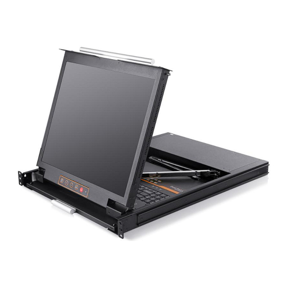
User Manual 8 Port /16 Port /24 Port/32 Port Product Overview 1.1 Brief Introduction The LED panel and keyboard/touchpad modules slide independently of each other, the keyboard/touchpad module slides back to “hide away” when not in use, while the thin profile LED monitor rotates backflush against the rack allowing administrators to easily monitor computer. -
Page 5: Appearance
User Manual 8 Port /16 Port /24 Port/32 Port Broadcast mode--operations simultaneously performed on all selected computers PS/2 keyboard and mouse emulation Manage server all around the world Remote access to the KVM(Keyboard,video and mouse) through modem ... -
Page 6: Rear View
User Manual 8 Port /16 Port /24 Port/32 Port Rear View RS232 100V~240V AC/47~63Hz CONSOLE -48V -36V~-72V DC IN RS232 100V~240V AC/47~63Hz CONSOLE RS232 100V~240V AC/47~63Hz CONSOLE -48V -36V~-72V DC IN RS232 100V~240V AC/47~63Hz CONSOLE 1-1 rear view Explanation Ground connecting screw Power input (AC or DC) Power Switch Local Console... -
Page 7: Structure And Size
User Manual 8 Port /16 Port /24 Port/32 Port Structure and Size 19.6 31.76 Diagram 1-3: console size 2. Installation and Start-up 2.1 system requirement Hardware Item Description Local Host 8 ,16,24,32 PC/server Local Console One USB keyboard,one USB mouse and one monitor Remote Console 1 PC or multiple computers connected to the network Software... -
Page 8: When The Server Is Up And Running
User Manual 8 Port /16 Port /24 Port/32 Port 2.2 When the server is up and running The KVM-over-IP gives you a full control over the remote server. The Management Console allows you to access the remote server’s graphics, keyboard and mouse and to send special commands to the server. -
Page 9: Rack Mounting
User Manual 8 Port /16 Port /24 Port/32 Port 2.4 Rack Mounting A standard rack mounting kit is provided to mount the switch in a depth of 650-850mm (17”), 670-800mm (19”) in a standard 19”rack. With one person hold the switch in place and the other person slides the L bracket into the switch’s side mounting brackets from the front to the back, then screws the brackets to the rack. -
Page 10: Install Kvm Components
User Manual 8 Port /16 Port /24 Port/32 Port 2.5 Install KVM Components Diagram 2.3 Installation diagram Installation Steps: 1) Make sure the KVM console has been connected to the ground. 2) Connect the KVM adapter to the host. 3) Connect the KVM adapter to the KVM port with CAT5 cable. 4)... -
Page 11: Cascade Installation
User Manual 8 Port /16 Port /24 Port/32 Port 2.6 Cascade Installation Diagram 2.4 cascade installation Explanation: Connect one port of the CAT5 cable to any RJ45 port of the console, and connect the other port to the RJ45 port with “Chain in”of the KVM switch. Repeat above operation to cascade more KVM switches. - Page 12 User Manual 8 Port /16 Port /24 Port/32 Port Module Explanation PS/2 CPU module USB CPU module Table 1.1:Module LED indication Components Function Green light The module has been powered on flashing Power LED Green light The module has been connected keeps on to the KVM switch Flashing...
-
Page 13: Opening The Console
User Manual 8 Port /16 Port /24 Port/32 Port 2.7 Opening the Console Release the release catch 2-1.3 unlocking Pull the LED panel all the way out until it clicks into place. Rotate the LED module all the way back to expose the LED screen; the LED - 13 -... - Page 14 User Manual 8 Port /16 Port /24 Port/32 Port module can be rotated up to108° . Pull the keyboard module all the way out until it clicks into place. Note: The keyboard module can’t bear extra load or any surface pressure. - 14 -...
-
Page 15: Closing The Console
User Manual 8 Port /16 Port /24 Port/32 Port The KVM makes two “beep” sounds after power on; an OSD window appears for you to input user name and password. 8 Port /16 Port: The orange LED and LED tube are flashing before you enter your password. -
Page 16: Led Operation
User Manual 8 Port /16 Port /24 Port/32 Port 3. LED OSD Configuration The LED OSD allows you to set up and configure the LED display. Buttons Functions Press this button invokes the menu function MENU SELECT and brings up the main menu. Press this button exits the current menu and return to the previous menu or press this EXIT/AUTO... -
Page 17: Osd Operation
User Manual 8 Port /16 Port /24 Port/32 Port 4. OSD Operation 4.1 OSD Overview Double click the right button of the mouse or double click hotkey【Scroll Lock】 to invoke below OSD main menu. You can customize the OSD hotkeys; find more details in OSD function instructions. -
Page 18: Osd Functions
User Manual 8 Port /16 Port /24 Port/32 Port 4.2 OSD Functions Menu Keys Submenu/Explanation Set User login-Set User login account and password Set accessible-Set access permissions BRC Mode -monitor multiple computers at the same time Load Default-reset the menu to the original factory default settings All-Lists all the ports on the installation Power On-lists only powered on ports that have... - Page 19 User Manual 8 Port /16 Port /24 Port/32 Port Menu Overview Operating instructions 1) Press【F1】or 【←】 【→】enters the F1 submenus. 2) Press 【↑】 【↓】moves the highlight bar to select the submenu. 3) Press 【Enter】 selects and exits ADM menu. 4) Press【Esc】cancels the operation and exits ADM menu.
- Page 20 User Manual 8 Port /16 Port /24 Port/32 Port 2. Set Accessible—press [Enter] to select Set Accessible, then below menu appears: (diagram 4-1.3) Diagram 4-1.3 Menu Explanation Full access function to the station and can do any FULL operation to the ports Read only function, you can only read the port but VIEW you can’t operate it if set this function.
- Page 21 User Manual 8 Port /16 Port /24 Port/32 Port 3. BRC Mode Off - Press [Enter] to enter the BRC mode, enter the main menu, press F7 to add or delete a port that need broadcast function. When BRC mode is effect, a speaker symbol appears in QV column.
- Page 22 User Manual 8 Port /16 Port /24 Port/32 Port 4. Load Default--- press [Enter] to select the submenu, all the set values are restoring to original factory default settings. Menu Overview Operating instruction 1) Press【F2】or 【←】 【→】enters the F2 submenus. 2) Press 【↑】...
- Page 23 User Manual 8 Port /16 Port /24 Port/32 Port Menu Overview Operating instructions 1) Press【F3】or 【←】 【→】enters the F3 submenus. 2) Press 【↑】 【↓】moves the highlight bar to select the submenu. 3) Press【Enter】selects and exits Set menu. 4) Press【Esc】cancels the operation and exits Set menu.
- Page 24 User Manual 8 Port /16 Port /24 Port/32 Port Menu Overview Operating instructions 1) Press 【 F4】 or 【←】 【 →】 enters the F4 submenus. 2) Press 【↑】 【 ↓】moves the highlight bar to select the submenu. 3) Press【Enter】 selects and exits Tool menu.
- Page 25 User Manual 8 Port /16 Port /24 Port/32 Port F6-Edit port names Choose the port with【↑】 【↓】 key; Press F6 and key in the new name or modify the old one, then press Enter to save the name and exit editing. ...
-
Page 26: Cascade Function
User Manual 8 Port /16 Port /24 Port/32 Port 4.3 Cascade Function 1. Operate the host computer under cascade Diagram 4-1.5 Diagram 4-1.6 Explanation: Shows that we have already connected an 8 port KVM to port 2(see diagram 4-1.5), we can connect 8 computers to the 8 port KVM. -
Page 27: Ip Settings
User Manual 8 Port /16 Port /24 Port/32 Port 5.IP Settings 5.1 Initial IP Configuration via Network IP - KVM factory default settings: DHCP forbidden Default IP address 192.168.0.70 Default Subnet mask 255.255.255.0 1) Read the CD and double click JAVA, ensure the Internet is available and install the JAVA step by step according to indications. - Page 28 User Manual 8 Port /16 Port /24 Port/32 Port 5.2 Configuration Setup via Serial Console For using serial terminal, the KVM-over-IP has a serial line interface (host side). This connector is compliant with the RS-232 serial line standard. The serial line has to be configured with the parameters given in Table below.
-
Page 29: Logging In
User Manual 8 Port /16 Port /24 Port/32 Port 6. Log in 1) Open IE and type in the IP address you have set in PSETUP (as shown above number 1). http:// 192.168.0.70(the IP address you have set according to your network area) 2) A screen appears as shown in above to indicate you to type your account and password after connected. -
Page 30: Remote Control
User Manual 8 Port /16 Port /24 Port/32 Port 6.1 Remote Console The Remote Console is the redirected screen, keyboard and mouse of the remote host system to that KVM-over-IP control. Main window of the remote console KVM-IP Diagram 6-1 Main window of the remote console Warning: In difference to the remote host system, the Remote Console window on your local window system is just one window among others. - Page 31 User Manual 8 Port /16 Port /24 Port/32 Port Ctrl+Alt+Delete Special button key to send the “Control Alt Delete” key combination to the remote system. Auto Adjust button If the video display is of bad quality or distorted in some way, press this button and wait a few seconds while the KVM-over-IP tries to detect the video mode of VGA port to the controlled host and adjust itself for the best possible video quality.
- Page 32 User Manual 8 Port /16 Port /24 Port/32 Port Diagram 6-3 Remote console options menu Diagram 6-4 Remote Console Options Menu:Scaling - 32 -...
- Page 33 User Manual 8 Port /16 Port /24 Port/32 Port Diagram 6-5 Remote Console Options Menu:Cursor Diagram 6-6 Video Settings panel - 33 -...
- Page 34 User Manual 8 Port /16 Port /24 Port/32 Port Diagram 6-7 soft keyboard Diagram 6-8 Soft Keyboard Mapping - 34 -...
- Page 35 User Manual 8 Port /16 Port /24 Port/32 Port Diagram 6-9 Encoding Compression - 35 -...
- Page 36 User Manual 8 Port /16 Port /24 Port/32 Port Diagram 6-10 Predefined Compression Diagram 6-11 Lossy Compression - 36 -...
- Page 37 User Manual 8 Port /16 Port /24 Port/32 Port Diagram 6-12 Encoding Color depth Remote status console Diagram 6-13 Status Line Both the incoming (“In:”) and the outgoing (“Out:”) network traffic are visible (in kb/s). If compressed encoding is enabled, a value in brackets displays the compressed transfer rate.
-
Page 38: Ip Menu
User Manual 8 Port /16 Port /24 Port/32 Port 7. IP Menu 7.1 Remote console KVM console KVM-IP Diagram 7-1 - 38 -... -
Page 39: Telnet Console
User Manual 8 Port /16 Port /24 Port/32 Port Telnet Control Diagram 7-2 Telnet console The KVM-over-IP firmware features a Telnet server that enables a user to connect via a standard Telnet client. In case the Telnet program is using a VT 100, VT 102 or VT 220 terminal or an according emulation, it is even possible to perform a console redirection as long as the KVM-over-IP host machine is using a text mode screen resolution. -
Page 40: Remote Wake-Up
User Manual 8 Port /16 Port /24 Port/32 Port Remote Wake-up IThe IP-KVM provides the remote power wakeup function, which can remotely wake up the sleeping computer. With this feature, the computers that are not in use for now can be shut down and remotely wake up the computer when want to use it, and thus save the power energy. - Page 41 User Manual 8 Port /16 Port /24 Port/32 Port Make sure Wake on Magic packet is Enable. - 41 -...
- Page 42 User Manual 8 Port /16 Port /24 Port/32 Port Make sure the following two items are selected. - 42 -...
-
Page 43: Virtual Media
User Manual 8 Port /16 Port /24 Port/32 Port Settings on IP-KVM: The control can be easily set up from the web page. 1. Click on Remote Control > Remote Wakeup to bring up the configuration page. 2. Click on More entries to add additional controlled target 3. -
Page 44: Fdd Image
User Manual 8 Port /16 Port /24 Port/32 Port Below is the host computer screen (the computer which connected with IP KVM) Floppy Image Diagram 7-4 virtual media-floppy disk The maximum image size is limited to 1.44MB. To use a larger image mount this image via Windows Share (or SAMBA) (see the Section called Use Image on Windows Share (via SAMBA) for details). - Page 45 User Manual 8 Port /16 Port /24 Port/32 Port Operation Procedures: You need to create the floppy image file first (Please refer to the section “Creating a floppy image”). For this example, we use RawWrite software (or any other image-creator software) to create floppy image. Please use licensed software for this purpose.
- Page 46 User Manual 8 Port /16 Port /24 Port/32 Port You may create a floppy image size up to 1.44Mb. This drive would be in read-only mode and would not allow you to write any information on this drive but copying only. This drive would be bootable under DOS mode if the motherboard/BIOS on the host computer supporting USB BOOTABLE function.
-
Page 47: Cd/ Dvd Image
User Manual 8 Port /16 Port /24 Port/32 Port CD/ DVD Image Use Image on Windows Share (via SAMBA) To include an image from a Windows share, select “CD/DVD Image” from the submenu. Diagram 7-5 Virtual Media - CD-ROM Image Share host The server name or its IP address (the PC that shares out the image file). - Page 48 User Manual 8 Port /16 Port /24 Port/32 Port Notes: The output image extension file name has to be ‘iso’, e.g. CD-Rom_vir.iso. You may create an ISO image size up to 650Mb (for CD-ROM). This drive would be in read-only mode and would not allow you to write any information on this drive but copying only.
- Page 49 User Manual 8 Port /16 Port /24 Port/32 Port Diagram 7-6 Explorer Context Menu Diagram 7-7 sharing configuration dialog - 49 -...
- Page 50 User Manual 8 Port /16 Port /24 Port/32 Port Adjust the settings for the selected directory. ■ Activate the selected directory as a share. Select Share this folder. ■ Choose an appropriate name for the share. You may also add a short description for this folder (input field Comment).
- Page 51 User Manual 8 Port /16 Port /24 Port/32 Port storage Cdrom_image.iso Open the remote console and you can see the virtual CD as below picture. - 51 -...
- Page 52 User Manual 8 Port /16 Port /24 Port/32 Port Creating an Image Creating a Floppy Image MS Windows You can use the tool “Raw Write for Windows”. You can get the RawWrite software from the website http://www.chrysocome.net/rawwrite. Diagram 7-8 RawWrite for Windows selection dialog From the menu, select the tab “Read”.
- Page 53 User Manual 8 Port /16 Port /24 Port/32 Port UNIX and UNIX-like OS To create an image file, make use of “dd”. This is one of the original UNIX utilities and is included in every UNIX-like OS (UNIX, Sun Solaris, and Linux). To create a floppy image file, copy the contents of a floppy to a file.
-
Page 54: Drive Redirection
User Manual 8 Port /16 Port /24 Port/32 Port UNIX and UNIX-like OS To create an image file, make use of “dd”. This is one of the original UNIX utilities and is included in every UNIX-like OS (UNIX, Sun Solaris, and Linux). To create a CD-ROM image file, copy the contents of the CD-ROM to a file. - Page 55 User Manual 8 Port /16 Port /24 Port/32 Port may confuse the remote host’s operating system. We recommend using the Drive Redirection with care, especially the write support. Disable Drive Redirection To disable the function of Drive Redirection. Force read-only connections If enabled the Write Support for the Drive Redirection is switched off.
- Page 56 User Manual 8 Port /16 Port /24 Port/32 Port Diagram 7-11 Built-in Java Drive Redirection 3. You can either redirect a local drive (only available under Windows) or redirect an ISO CD/DVD image. 3-1 If click on Connect Drive Select the drive to be redirected and click OK. Select the drive you would like to redirect.
- Page 57 User Manual 8 Port /16 Port /24 Port/32 Port Warning Please be cautious that if “Allow Write Support” is selected, all data on the shred media might be destroyed. Write Support This feature may be enabled here. Write support means that the remote computer is allowed to write on your local drive.
- Page 58 User Manual 8 Port /16 Port /24 Port/32 Port 3-2. If click on Connect ISO Select the ISO image file and click Open. 4. Finally the established Drive Redirection connection will be displayed - 58 -...
- Page 59 User Manual 8 Port /16 Port /24 Port/32 Port Open My Computer you will see the virtual drive appears on the remote host PC window. The drive redirection software tries to lock the local drive before it is redirected. That means that it tries to prevent the local operating system from accessing the drive as long as it is redirected.
-
Page 60: Virtual Drive
User Manual 8 Port /16 Port /24 Port/32 Port Virtual Drive Diagram 7-12 USB mass storage option Set this option to disable the mass storage emulation (and hide the virtual drive) if not mounting a image file or drive to the host system. To set this option, press the button “Apply”. -
Page 61: Changing Password
User Manual 8 Port /16 Port /24 Port/32 Port Change Password Diagram 7-13 Setting Passwords Change password of currently logged in user: Old Password: type in current password New Password: type in new password Confirm New Password: re-type new password for verification Click “Apply”... -
Page 62: Users And Groups
User Manual 8 Port /16 Port /24 Port/32 Port Users and Groups There are three kinds of levels of user accounts: ■ Super-- Has all possible rights to configure the device ■ Administrator -- Has partial rights to change configuration apart from critical settings ■... - Page 63 User Manual 8 Port /16 Port /24 Port/32 Port Confirm password Confirmation of the password above. Email address This is optional. Mobile number This information may be optionally provided. Role Each user can be a member of a group (named a “role” ) – there kinds can be shose from: super, administrator, or an regular user.
-
Page 64: Kvm Settings
User Manual 8 Port /16 Port /24 Port/32 Port 7.4 KVM Settings User Console The following settings are user specific. That means, the super user can customize these settings for every users separately. Changing the settings for one user does not affect the settings for the other users. - 64 -... - Page 65 User Manual 8 Port /16 Port /24 Port/32 Port Diagram 7-14 User Console Setting - 65 -...
- Page 66 User Manual 8 Port /16 Port /24 Port/32 Port Transmission Encoding The Transmission Encoding setting allows changing the image-encoding algorithm that is used to transmit the video data to the Remote Console window. It is possible to optimize the speed of the remote screen processing depending on the number of users working at the same time and the network bandwidth of the connection line (Modem, ISDN, DSL, LAN, etc.).
- Page 67 User Manual 8 Port /16 Port /24 Port/32 Port versions and offers wider range of functionality when run in SUN's JVM. Please make sure that you are installing Sun JVM v1.5 or above to your client system. Miscellaneous Remote Console Settings Start in Monitor Mode Sets the initial value for the monitor mode.
-
Page 68: Keyboard/Mouse
User Manual 8 Port /16 Port /24 Port/32 Port Keyboard/Mouse Diagram7-15 Keyboard and Mouse Settings PS/2 Keyboard Model Enables a certain keyboard layout. You can choose between “Generic 101-Key PC” for a standard keyboard layout, “Generic 104-Key PC” for a standard keyboard layout extendend by three additional windows keys, “Generic 106-Key PC”... -
Page 69: Video
User Manual 8 Port /16 Port /24 Port/32 Port Video Diagram 7-16 Video Settings Miscellaneous Video Settings •Noise filter This option defines how the IP-KVM reacts to small changes in the video input signal. Turning on the noise filter can help reduce video flickering that is often caused by distortions, as well as lowering unnecessary bandwidth consumption. - Page 70 User Manual 8 Port /16 Port /24 Port/32 Port 7.5 Device Settings - 70 -...
-
Page 71: Device Setings
User Manual 8 Port /16 Port /24 Port/32 Port Network The Network Settings panel allows changing network related parameters. Each parameter will be explained below. Once applied the new network settings will immediately come into effect. Diagram 7-17 Network Settings - 71 -... -
Page 72: Dynamic Dns
User Manual 8 Port /16 Port /24 Port/32 Port Warning Changing the network settings of the IP-KVM might result in losing connection to it. In case you change the settings remotely make sure that all the values are correct and you still have an option to access the IP-KVM. - Page 73 User Manual 8 Port /16 Port /24 Port/32 Port A freely available Dynamic DNS service (www.dyndns.org) can be used in the following scenario. Ethernet Administrator Router/NAT Private IP Public IP Internet IP-KVM Dynamic Server Diagram 7-19 Dynamic DNS Scenario The IP-KVM is reachable via the IP address of the DSL router, which is dynamically assigned by the provider.
- Page 74 User Manual 8 Port /16 Port /24 Port/32 Port Hostname This is the hostname of the IP-KVM that is provided by the Dynamic DNS Server. (Use the whole name including the domain, e.g. testserver.dyndns.org, not just the actual hostname). Username You have registered this username during your manual registration with the Dynamic DNS Server.
-
Page 75: Security
User Manual 8 Port /16 Port /24 Port/32 Port Security Diagram 7-22 IP Filter Settings - 75 -... -
Page 76: Certificate
User Manual 8 Port /16 Port /24 Port/32 Port Certificate Diagram 7-23 Certificate Settings The IP-KVM uses the Secure Socket Layer (SSL) protocol for any encrypted network traffic between itself and a connected client. During the connection establishment the IP-KVM has to expose its identity to a client using a cryptographic certificate. - Page 77 User Manual 8 Port /16 Port /24 Port/32 Port done, click on the button “Create” which will initiate the Certificate Signing Request generation. The CSR can be downloaded to your administration machine with the “Download CSR” button. • Send the saved CSR string to a CA for certification. You will get the new certificate from the CA after a more or less complicated traditional authentication process (depending on the CA).
- Page 78 User Manual 8 Port /16 Port /24 Port/32 Port Diagram 7-25 CSR string After completing these three steps, the IP-KVM has its own certificate that is used for identifying the IP-KVM to its clients. Warning If you destroy the CSR on the IP-KVM there is no way to get it back! In case you deleted it by mistake, you have to repeat the three steps as described above.
- Page 79 User Manual 8 Port /16 Port /24 Port/32 Port Locality/City The city where the organization is located. State/Province The state or province where the organization is located. Country (ISO code) The country where the organization is located. This is the two-letter ISO code, e.g. DE for Germany, or US for the USA.
-
Page 80: Serial Port
User Manual 8 Port /16 Port /24 Port/32 Port Serial Port Diagram 7-27 Serial Port - 80 -... -
Page 81: Date/Time
User Manual 8 Port /16 Port /24 Port/32 Port Date / Time Diagram 7-28 Date / Time This link refers to a page, where the internal real-time clock of the IP-KVM can be set up. You have the possibility to adjust the clock manually, or to use a NTP timeserver. -
Page 82: Event Log
User Manual 8 Port /16 Port /24 Port/32 Port Event Log Diagram 7-29 Event Log Important events like a login failure or a firmware update are logged to a selection of logging destinations. Each of those events belongs to an event group, which can be activated separately. - Page 83 User Manual 8 Port /16 Port /24 Port/32 Port Settings you can choose how many log entries are shown on each page. Furthermore, you can clear the log file here. List logging enabled The common way to log events is to use the internal log list of the IP-KVM. To show the log list, click on “Event Log”...
- Page 84 User Manual 8 Port /16 Port /24 Port/32 Port Here is a example of all gerenated event and its event group. Device succesfully started device Board Reset performed by user... device Firmware upload failed. device No firmware file uploaded. device Uploaded firmware file discarded.
-
Page 85: System Maintenance
User Manual 8 Port /16 Port /24 Port/32 Port 7.6 System Maintenance The administrator performs various maintenance activities on the IP-KVM. These include viewing its status, update firmware, view the event log and reset the unit. Device Information The Device Status page contains a table with information about the IP-KVM’s hardware and firmware. - Page 86 User Manual 8 Port /16 Port /24 Port/32 Port Diagram 7-30 Device Information The Data file for support allows you to download the IP-KVM data file with specific support information. This is an XML file with certain customized support information like the serial number etc.
-
Page 87: Event Log
User Manual 8 Port /16 Port /24 Port/32 Port Figure above displays the IP-KVM activity. From left to right the connected user(s), its IP address (from which host the user comes from) and its activity status is displayed. RC means that the Remote Console is open. If the Remote Console is opened in exclusive mode the term (exclusive mode) is added. -
Page 88: Upgrade Firmware
User Manual 8 Port /16 Port /24 Port/32 Port Update Firmware Firmware can be easily upgraded via web page. This section describes the upgrade procedures. Diagram 7-33 Update Firmwares The IP-KVM is a complete standalone computer. The software it runs is called firmware. - Page 89 User Manual 8 Port /16 Port /24 Port/32 Port Warning!!! This process is not reversible and might take few minutes. During this upgrading process, we should not disconnect the power or the Ethernet cable, since it may causes upgrade failure and destroy the image in Flash memory. The IP-KVM will automatically initiate a self-reboot upon completion of upgrade process to make newly upgraded firmware effective.
- Page 90 User Manual 8 Port /16 Port /24 Port/32 Port The panel shows you the version number of the currently running firmware and the version number of the uploaded firmware. Pressing Update will store the new version and substitute the old one completely. After the firmware updated successfully, the device will be rebooted and redirected to the login web page automatically.
- Page 91 User Manual 8 Port /16 Port /24 Port/32 Port Check out the device information to see the updated firmware is running. Unit Reset This section allows you to reset specific parts of the device. This involves resetting keyboard/mouse, USB, video engine, or the IP-KVM device itself. In general, the IP-KVM requires a reset when implementing a firmware update.
-
Page 92: Unit Reset
User Manual 8 Port /16 Port /24 Port/32 Port Diagram 7-34 Unit Reset To reset a certain IP-KVM functionality click on the Reset button as displayed in figure below. Clicking on Reset of Reset Device will reboot the IP-KVM system. It will close all current connections to the administration console and to the Remote Console. -
Page 93: Appendix
User Manual 8 Port /16 Port /24 Port/32 Port Appendix USB Emulation Keyboard Mac Keyboard The PC compatible (101/104 keys) keyboard can emulate the functions of the Mac keyboard. The emulation mappings are listed in the below table: PC Keyboard MAC Keyboard [Shift] Shift... -
Page 94: Sun Keyboard
User Manual 8 Port /16 Port /24 Port/32 Port Sun Keyboard The PC compatible (101/104 keys) keyboard can emulate the functions of the Sun keyboard when the control key [L_Win] is used in conjunction with other keys.The corresponding functions are shown in the below table: PC Keyboard Sun Keyboard L_Win&L_Alt... -
Page 95: Specifications
User Manual 8 Port /16 Port /24 Port/32 Port Specifications Model DL2908i DL2916i DL2924i DL2932i Direct Computer Connections 1024 Keyboard Port Emulation PS/2,USB Mouse Model SXGA TFT View Area 19″ Optimum 1280×1024@60Hz Resolution LED Monitor Color 16.7 M 250cd/m² ( T y p )...
Need help?
Do you have a question about the DL2908i and is the answer not in the manual?
Questions and answers