Table of Contents
Advertisement
Quick Links
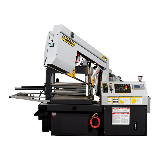
M-16A & M-20A PLC 500 E600 & PLC 100 E200
2005 Revision F
393059 May 2005
THANK YOU,
On behalf of everyone at HYD . MECH, I would like to thank and congratulate you on your decision to purchase a
HYD . MECH band saw.
Your new machine is now ready to play a key role in increasing the efficiency of your operation, helping you to reduce cut-
ting costs while boosting quality and productivity.
To ensure you are maximizing the power and versatility of your new HYD . MECH band saw, please take the time to famil-
iarize yourself and your employees with the correct operation and maintenance procedures as outlined in this manual.
We sincerely appreciate the confidence you have demonstrated in purchasing our product and look forward to building a
long and mutually beneficial relationship.
Thank-you.
HYD . MECH GROUP LIMITED
P.O. BOX 1030, 1079 Parkinson Road
Woodstock, Ontario Canada, N4S 8A4
Phone: (519) 539-6341
Service 1-877-237-0914
Sales 1-877-276-SAWS(7297)
Fax (519) 539-5126
e-mail, info@hydmech.com
01
Advertisement
Table of Contents
Troubleshooting


Need help?
Do you have a question about the M-16A and is the answer not in the manual?
Questions and answers
I need help with repairs
The repair options for the Hyd-Mech M-16A include repair or replacement of defective parts at Hyd-Mech’s factory, warehouse, or an approved repair shop. The user must prepay return freight. The warranty does not cover maintenance items such as lubricating grease, oils, filters, V-belts, and saw blades, nor does it cover damages from neglect, overloading, abuse, accidents, inadequate maintenance, or unauthorized alterations. Components not originally manufactured by Hyd-Mech, such as motors, gearboxes, pumps, electric components, valves, hoses, and fittings, are covered under their original manufacturer’s warranty. Hyd-Mech provides assistance and information to facilitate claims with the original manufacturer.
This answer is automatically generated
M-20A saw. An older one maybe 2003-2007. I need a picture of your older control panel labels for the buttons as mine are missing. Also I'm having trouble; after I set the desired cut quantity, length etc. it's not giving me any prompt nor option to initiate the input cut order I entered. When I click start cycle the button flows yellow for a moment but that's it. After I enter in Rq, CT, length, etc. what do I push to actually order the machine to initiate those cuts
The control panel button labels are not fully listed, but the following functions are mentioned:
- CYCLE START: Used to start or pause a job.
- F8: Used to clear the queue when working with multiple jobs.
To initiate a cut order after entering the desired cut quantity and length:
1. Ensure all switches are in the center neutral position.
2. Press the CYCLE START button to begin the AUTO CYCLE.
3. If the job is paused, pressing CYCLE START again resumes it.
4. Make sure that the “QTY RQ’D” is greater than “QTY CUT” for the AUTO CYCLE to start.
If running multiple jobs, use F8 to clear the queue and enter job numbers.
This answer is automatically generated