Table of Contents
Advertisement
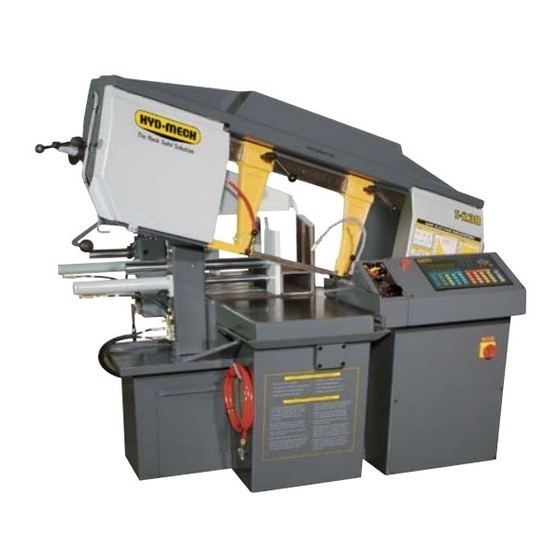
S-20/23 A
395427
January 2006 Revision A
THANK YOU,
On behalf of everyone at HYD . MECH, I would like to thank and congratulate you on your decision to purchase a HYD .
MECH band saw.
-
ting costs while boosting quality and productivity.
To ensure you are maximizing the power and versatility of your new HYD . MECH band saw, please take the time to famil-
iarize yourself and your employees with the correct operation and maintenance procedures as outlined in this manual.
Thank-you.
HYD . MECH GROUP LIMITED
P.O. BOX 1030, 1079 Parkinson Road
Woodstock, Ontario Canada, N4S 8A4
Phone: (519) 539-6341
Service 1-877-237-0914
Sales 1-877-276-SAWS(7297)
Fax (519) 539-5126
e-mail: info@hydmech.com
1
Advertisement
Table of Contents
Troubleshooting

Related Manuals for Hyd-Mech S-20 A


Summary of Contents for Hyd-Mech S-20 A
- Page 1 S-20/23 A 395427 January 2006 Revision A THANK YOU, On behalf of everyone at HYD . MECH, I would like to thank and congratulate you on your decision to purchase a HYD . MECH band saw. ting costs while boosting quality and productivity. To ensure you are maximizing the power and versatility of your new HYD .
-
Page 3: Table Of Contents
TABLE OF CONTENTS SECTION 0 - SAFETY INSTRUCTIONS SUMMARY ............................0.1 BASIC RULES ..........................0.4 RESPONSIBILITIES OF THE OWNER ...................0.5 RESPONSIBILITIES OF THE OPERATOR AND MAINTENANCE PERSONNEL ......0.6 SECTION 1 - INSTALLATION INSTALLATION..........................1.1 SAFETY PRECAUTIONS ........................1.1 LIFTING THE S-20/23A WITH A FORK LIFT ..................1.2 WRAPPED FOR SHIPPING ......................1.2 REMOVING THE SAW FROM THE SKID ..................1.2 LEVELLING THE SAW ........................1.3... - Page 4 SECTION 4 - ELECTRICAL MAIN PANEL: COMPONENT LAYOUT ..................4.1 PCB BOARD: FUSE LOCATION ....................4.2 MAIN PANEL: COMPONENT LAYOUT ..................4.3 MAIN PANEL: COMPONENT LAYOUT ..................4.4 MAIN PANEL: COMPONENT LAYOUT ..................4.5 ELECTRICAL SCHEMATIC DRAWING NUMBERS ...............4.6 FOR ELECTRICAL SCHEMATICS AND COMPONENTS PARTS LIST SEE PDF ON ATTACHED CD.
-
Page 5: Section 0 - Safety Instructions
SECTION 0 - SAFETY INSTRUCTIONS SUMMARY All persons operating this machine must have read and understood all of the following sections of this Manual: Section 0 SAFETY Section 2 OPERATING INSTRUCTIONS However, as a memory aid, the following is a summary of the Safety Section. Put Safety First Mandatory Information –... - Page 6 FOREWORD Put Safety First! This Safety Section contains important information to help you work safely with your machine and describes the dangers inherent in our machines. Some of these dangers are obvious, while others are less evident. It really is important to PUT SAFETY FIRST. Make it a habit to consider the hazards associated with any action BEFORE from your supervisor.
- Page 7 Signatures I have read and understood all parts of Section 0 – Safety, and Section 2 – Operating Instructions. Name Date Signature I have read and understood all parts of this Operation and Maintenance Manual. Name Date Signature...
-
Page 8: Basic Rules
Manual. Hyd-Mech Group cannot accept any liability for personal injury or property damage due to operator errors or non-compliance with the Safety and Operating Instructions contained in this Manual. -
Page 9: Responsibilities Of The Owner
Responsibilities of the owner Organization of work This Operation and Maintenance Manual must always be kept near the machine so that it is accessible to all concerned. The general, statutory and other legal regulations on accident prevention and environmental protection must also be observed, in addition to the Manual material. -
Page 10: Responsibilities Of The Operator And Maintenance Personnel
Responsibilities of the operator and maintenance personnel Safety equipment All machines are delivered with safety equipment that must not be removed or bypassed during operation. The correct functioning of safety equipment on the machine must be checked: at the start of every shift. after maintenance and repair work Emergency Stop Button ( E-Stops) Always be aware of the location of the Emergency Stop Button(s). - Page 11 Gloves Experience has shown that careless use of gloves around machinery is a major factor in serious hand injuries. Gloves should not be worn when operating or adjusting the machine, except: Wear protective gloves when handling bandsaw blades at blade changes. Gloves may be worn when handling work pieces, only if the machine is in Manual Mode and the bandsaw blade is not running.
- Page 12 On Hyd-Mech machines the Master Disconnect Switch will be of one of three types: Rotary switch mounted in electrical control cabinet door and inter-locked with door...
-
Page 13: Section 1 - Installation
MAINTAIN PROPER ADJUSTMENT OF BLADE TENSION, BLADE GUIDES, AND THRUST BEARINGS HOLD WORK PIECE FIRMLY AGAINST TABLE DO NOT REMOVE JAMMED CUTOFF PIECES UNTIL BLADE HAS STOPPED NO MODIFICATIONS TO THE MACHINE ARE PERMITTED WITHOUT PRIOR APPROVAL FROM HYD-MECH. ANY AP- PROVED MODIFICATIONS SHOULD ONLY BE UNDERTAKEN BY TRAINED PERSONNEL. -
Page 14: Lifting The S-20/23A With A Fork Lift
LIFTING THE S-20/23A WITH A FORK LIFT The S-20/23A is shipped with a shipping pallet attached to the saw. When lifting the pallet with a forklift truck make sure pallet length dimension is 84" (2132 mm). Minimum fork length of 72" (1827 mm) is recommended to safely lift the pallet. WRAPPED FOR SHIPPING The S-20/23A is shrink-wrapped for shipping from our plant. -
Page 15: Levelling The Saw
LEVELLING THE SAW Use a machinist's level across the vise table to level the saw. Adjust the level with the leveling bolts supplied. Consider- give a small incline towards this area helps to ensure the coolant supply returns to the container. HYDRAULIC OIL The S-20/23A option is supplied with ISO VG22 hydraulic oil. -
Page 17: Section 2 - Operating Instructions
SECTION 2 – OPERATING INSTRUCTIONS This section has been prepared to give the operator the ability to set up the saw for most cutting situations. Before starting the bandsaw, or cutting any material, the operator should be familiar with all operations and controls as well as the basic cutting theory described below. - Page 18 PANEL MOUNTED PUSHBUTTONS AND SELECTOR SWITCHES Front Vise – This selector switch has three positions, OPEN, NEUTRAL, and CLOSE This switch must be in NEUTRAL before the hydraulic system can be started. In OPEN, the front (saw) vise will open all the way, or until the switch is released.
-
Page 19: Hmi Keys
counters enough resistance to stop it. Blade Start – A green pushbutton, illuminated whenever the blade motor is running To start the blade motor, the Hydraulics must be running, and the head must not be on the Head Down Limit Switch. In Single Cut Cycle and Auto Cycle, the PLC Interface Display prompts Blade Start to enable the cycle to continue. -
Page 20: Display
DISPLAY The display communicates with the operator through the 8 different screens shown in the Screen Map on page In addition there are the following special screens Start-up screens – actually a group of screens that display in rapid sequence at start-up. PLC Parameter Screen –... - Page 21 Manual Mode MACHINE intermediate screens to Machine Start screen (only active with Front Vise, Shuttle Vise, START WASH STOP and Head switches all in neutral). - Press F1 function key labeled START. Hydraulics start and display change to Manual Mode. - WASH will start the coolant pump motor.
- Page 22 Single Cut Mode MACHINE intermediate screens to Machine Start screen (only active with Front Vise, Shuttle Vise, START WASH STOP and Head switches all in neutral). - Press F1 function key labeled START. Hydraulics start and display change Manual Mode. - WASH will start the coolant pump.
- Page 23 Shuttle vise opens Shuttle moves towards Home (full forward position) Shuttle retracts to preset length position Shuttle Vise closes Front Vise opens Shuttle advances to Home Front Vise closes Head descends, making cut and when cut is complete, Head rises to Head Up Position Blade stops and display returns to Single Cut Start Screen Auto Mode MACHINE...
-
Page 24: Plc 100 Control System
- Shuttle vise opens - Shuttle moves towards Home (full forward position) - Shuttle retracts to preset length position - Shuttle Vise closes - Front Vise opens - Shuttle advances to Home - Front Vise closes - Head descends, making cut - When cut is complete - The blade motors shut down - Display returns to Single Cut Start Screen and hydraulic pump motor will run for a pre-... - Page 25 MODE CONTROLS SERVICE MODE The SERVICE MODE allows the user to adjust the various PLC parameters. The user will be prompted for a password. Contact Hyd-Mech Group Limited to access this mode. MANUAL MODE Pressing this key will enable all of the “MANUAL MODE ONLY CONTROLS.”...
- Page 26 AUTO MODE Pressing this key will disable all of the “MANUAL MODE ONLY CONTROLS.” To enter AUTO MODE, the FIXED VISE must be activated. MACHINE & CYCLE CONTROLS MACHINE START Pressing this key will activate the control panel, display, and start the hydraulic system.
- Page 27 SINGLE CUT MODE BLADE SPEED 0 SFM LENGTH 0” 7. When the cut is completed, the head will rise to the head up limit switch, the blade will stop and the display window will reset for the next cut. 8. To cut another piece, repeat steps 2 through 6. NOTES: 1.
- Page 28 AUTOMATIC MODE JOB # PIECES REQUIRED PIECES CUT LENGTH 2. After the values are entered, press the CYCLE START button. The switch will illuminate, the display window will prompt you to start the blade for a trim cut (if the “Trim Cut” parameter has been selected). CAUTION: If the head is in its full down position it will rise to the head up limit so that no damage to the blade will occur.
- Page 29 WORKING WITH A QUEUE The purpose of a QUEUE is to allow the operator to run several jobs (maximum of 10) in series if they are of the same material and shape. To run a QUEUE, it is necessary to program in all job values as is done with programming a single job. After in the desired sequence.
-
Page 30: Mechanical Controls
KERF CORRECTION FOR ANGLE CUTTING When making mitered cuts, the part length must be set longer than the desired length by an amount called the KERF CORRECTION or the kerf value must be adjusted. This is due to the fact that the PLC will not account for a difference in the kerf value at various angles. - Page 31 Head in the fully down position and move the Head until the frame meets the 90 stop bolt which is located on the vise post. HEAD UP LIMIT SETTING The Head Up limit setting allows the operator to set the height that the Head will ascend to after a cut is completed.
- Page 32 pulse per minute is optimum – more is not better. Air Screw – regulates the jet of air that projects the lubricant from the nozzle onto the blade. Adjustment should be such that lubricant covers the blade without blowing the mist beyond the back edge of the blade. GUIDE ARM POSITIONING The S-20/23A Series II guide arms are adjustable to accommodate varying material widths.
- Page 33 Saw Cutting Parameters Chart HYDRAULIC FEED CONTROL Feed Force Knob Used to set Feed Force Limit (counterclockwise rotation to increase and clockwise rotation to decrease). Fast Approach Lever Depress for fast head descent. Feed Rate Knob Used to set Feed Rate (counterclockwise rotation to increase and clockwise rotation to decrease).
- Page 34 CHART EXAMPLE #1 We will use the parameters chart to set up the saw for cutting 8” (200mm) diameter #1045 Carbon Steel. STEP 1 – DETERMINE EFFECTIVE MATERIAL WIDTH (w) (INCHES) OR (mm) Effective material width W (in.) for most common shapes of materials is the widest solid part of the material to be in contact with blade during cutting.
- Page 35 pitch changes for differing effective material widths. It is impractical to change the blade to the proper pitch every time a different width of material is cut and it is not necessary, but remember be fed slower on wide material because the small gullets between the teeth will get packed with chips before they get across and out of the cut.
- Page 36 cept where there is a vibration problem. If the blade vibrates appreciable at optimum speed as most often occurs with structurals and bundles, a lower blade speed may reduce vibration and prevent premature blade failure. 2. Material Hardness – The graph above illustrates blade speed curves for materials of hardness 20 RC (225 Bhn) or lower.
- Page 37 Optimum Shading indicates opti- Pitch mum and actual pitch and required multiplier at point 10/14 of intersection, for the given 8/12 example. 6/10 0.67 0.54 0.42 0.29 0.21 1.4/2.5 0.17 .85/1.5 10/14 8/12 6/10 1.4/2.5 .85/1.5 Optimum versus Actual Blade Pitch feed rate, fr, by above factors mum blade (e.g.
- Page 38 Step 1 – Effective material width: 5” (.6 x 8”) or 120mm (.6 x 200) Step 2 – Feed force limit setting for 8” diameter material. Refer to Feed Force Limit setting in Step 2 Step 3 – Optimum blade pitch (TPI): ¾ TPI Step 4 –...
-
Page 39: Section 3 - Maintenance And Troubleshooting
SECTION 3 – MAINTENANCE AND TROUBLESHOOTING SAFETY DURING MAINTENANCE AND TROUBLESHOOTING “Lock-out”, or “Lock-out Tag-out” are terms that refer to procedures taken to prevent the unexpected start-up, or other re- lease of energy, by a machine, whenever anyone is required to remove or bypass safety guards or devices, or whenever anyone is required to place part of his body in a hazard area. -
Page 40: Blade Changing Procedure
BLADE CHANGING PROCEDURE NOTE: Wear gloves for protection from the sharp blade. Open the idler wheel and drive wheel doors and swing the head to 45 as this will make it easier to grip the blade closer to both wheels Loosen the Blade Tensioner by turning counter clockwise. -
Page 41: Blade Guide Adjustment
S-23 BLADE TENSION ASSEMBLY S-20 BLADE TENSION ASSEMBLY BLADE GUIDE ADJUSTMENT At the bottom of the guide arms are the carbide blade guide assemblies, the photo shows the carbide-locking handle. These assemblies will need to be adjusted occasionally as the carbide pads become worn. To adjust properly, follow this simple procedure. -
Page 42: Blade Brush Adjustment
BLADE BRUSH ADJUSTMENT The machine leaves the factory with the blade brush adjusted for maximum life of the brush. This setting places the ends of the blade brush wires so as to contact the blade at the bot- tom of the blade gullets. The plastic drive wheel that is driven by the drive wheel face should be held against the blade face with the minimum force that is necessary. -
Page 43: Lubrication
LUBRICATION The S-20/23A Series II was designed to minimize the maintenance requirements, however moving assemblies and contact faces need lubrication on a regular schedule. The lubrication requirements are primarily the saw pivot points and wear and seizure. It is recommended to use LPS ThermaPex Hi-Load bearing Grease manufactured by LPS Laboratories or equivalent, for The lubricant should be applied as frequently as required. -
Page 44: Gearbox Lubrication
GEARBOX LUBRICATION S-20A S320 synthetic oil. This oil has an ISO Viscosity Grade of 320 that is optimum for ambient temperatures from 20-70 Deg C (70-140 Deg F). The W86 was designed to be a sealed unit, so no oil change should be neces- approved Shell type be used, this be equivelent viscosity wise and of the synthetic type. -
Page 45: Hydraulic Maintenance
HYDRAULIC MAINTENANCE indicator is on red zone. Indicator should be checked with hydraulic pump running and after oil has reached operating temperaturee. replacement oils: Texaco Rando HD 46 CHEVRON ECO Hydraulic oil AW ISO 46 MOBIL DTE 25 ESSO NUTO H46 SHELL TELLUS OIL 46 HYDRAULIC OIL LEVEL - Oil level should be maintained in the upper half of the level gauge. - Page 46 An encoder is attached to the shuttle assembly and travels with the shuttle to provide length information to the PLC. A proximity switch is mounted behind the idler wheel, provides blade speed input to the PLC. The programmed information includes logic put into the PLC by its manufacturer, as well as information programmed in, through the keypad, by the assembly plant.
-
Page 47: Plc 100 Troubleshooting
BROKEN PROX Allows user to override signal from proximity switch in case it is broken. (When set to NO machine will not run with broken proximity sensor. Set to YES allows machine to run – but with out blade speed display and blade breakage or stall protection). SPD PROX DELAY Delay in monitoring of the blade speed proximity switch during acceleration of the blade from start to desired speed set by the manufacturer... - Page 48 properly a. At encoder connector: between 0 V pin and 24 V pin. This voltage should be a minimum of 22 to 26 VDC. If the voltage is incorrect, check encoder cable continuity – if OK, possible PLC problem. If the voltage is correct, go to step b) b.
- Page 49 Check the encoder cable connections. A loose connection could easily cause this concern. Remove the encoder from the machine and check that the shaft can rotate freely. There should be no binding or rough spots felt when spinning the shaft. Plug the encoder cable into the encoder, clear the length display, and rotate the shaft exactly (or as close as possible) one revolution.
-
Page 50: Fuses
40 ohms), shorted noise suppressor at the coil, or shorted wiring could be the cause. If the fuse is good and no output voltage condition still exists, with the output light on, then the relay is defective. If this is the case, the PLC will have to be returned to the manufacturer for repair. (Contact Hyd-Mech Group Limited Service Dept.) FUSES The PLC has four glass fuses in line with it. -
Page 51: Mitsubishi 100 Inputs And Outputs
DIAGNOSIS: Check POWER LED (see next page – Inputs & Outputs) – to be on when the PLC is switched on. If the light is OFF, PLC may have failed. Check for proper connection of cable at PLC & at interface. If light is not on – check the (2 amp) PLC fuse. -
Page 52: Calibration Procedure
Input/Output Terminal Information Inputs X0 – Shuttle Encoder, Channel A – (Open on “P”) X10 – Open (Shuttle Vise Close on Seq. and “P”) X1 – Shuttle Encoder, Channel B – (Open on “P”) X11 – Open (Shuttle Vise Open on Seq. and “P”) X2 –... - Page 53 General Rule: If part length error gets longer as programmed length increases: Existing ACTUAL LENGTH = 33.070” Change ACTUAL LENGTH to 33.070 - .020 = 33.050” TO ADJUST LENGTH CONSTANT VALUE: Cut length Programmed length X Existing LENGTH CONSTANT = New LENGTH CONSTANT Example: Cut length of 11.988”, Programmed length of 12”, Existing LENGTH CONSTANT parameter of 0.0012567.
-
Page 55: Section 4 - Electrical
SECTION 4 - ELECTRICAL MAIN PANEL: COMPONENT LAYOUT... -
Page 56: Pcb Board: Fuse Location
PCB BOARD: FUSE LOCATION FUSE DESCRIPTION 1 3FU1, 3FU2 1.5Amp Time Delay 2 4FU 2Amp Time Delay 3 5FU1, 5FU2 2Amp Fast Acting 4 6FU 5Amp Time Delay 5FU1 5FU2 3FU1 3FU2... -
Page 57: Main Panel: Component Layout
MAIN PANEL: COMPONENT LAYOUT COMMUNICATION CABLE PLC OUTPUT CABLE PLC INPUT CABLE INPUT CONNECTIONS OUTPUT CONNECTIONS... - Page 58 MAIN PANEL: COMPONENT LAYOUT POWER SUPPLY...
-
Page 59: Main Panel: Component Layout
MAIN PANEL: COMPONENT LAYOUT FUSE Description 1 2FU1, 2FU2 3Amp Time Delay 2 7FU 2Amp Fast Acting SAFETY RELAY 2FU1 2FU2... -
Page 60: Electrical Schematic Drawing Numbers
S20A 3HP OPTION PART # DESCRIPTION UNIT 342490 Gearmotor, 3 HP, W86, 230/460V, 3 Phase, 60Hz 1.00 S23A 5HP OPTION PART # DESCRIPTION UNIT 342554 Gearmotor, 5 HP, W110, 230/460V, 3 Phase, 60Hz 1.00 ELECTRICAL SCHEMATIC DRAWING NUMBERS S22AII - NA - 7 - 00 - 1 Schematic applies to all machines regardless if machine contains PLC or SEQUENCER option. -
Page 61: Section 5 - Hydraulic
SECTION 5 - HYDRAULIC The S20-A, S23-A hydraulic system does not require any special work on a new machine before its start up. The hydrau- ensure proper operation upon initial start up. HYDRAULIC COMPONENT LIST PART ITEM BALLOON DESCRIPTION NUMBER NUMBER 800006-S23A 800003-S22A... -
Page 62: Filler Cap And Filter Element Location
FILLER CAP AND FILTER ELEMENT LOCATION OIL LEVEL GAUGE AND DRAIN PLUG Oil level should be maintained at the top portion of the level gauge glass window. -
Page 63: For Hydraulic Schematics And Plumbing Diagrams See Pdf On Attached
FOR HYDRAULIC SCHEMATICS AND PLUMBING DIAGRAMS SEE PDF ON ATTACHED CD. -
Page 65: Section 6 - Mechanical Assemblies
SECTION 6 - MECHANICAL ASSEMBLIES For Mechanical Assembly Drawings see PDF on attached CD... -
Page 67: Section 7 - Optional Equipment
SECTION 7 - OPTIONAL EQUIPMENT OUT OF STOCK SWITCH length of material is available for the next length advance. Also stops the automatic cycle after completing the last cut. MIST COOLANT SYSTEM Mist Coolant – the air powered pump delivers a regulated number of pulses of lubri- cant to a single applicator nozzle. -
Page 68: Variable Vise Pressure Option
VARIABLE VISE PRESSURE OPTION Vise clamping pressure adjustment is located on the face of hydraulic power pack door. Clamping pressure is indicated by the pressure gauge adjacent to pres- sure control knob. Turning knob clockwise increases clamping pressure. The clamping pressure can be CONTROL KNOB GAUGE pressure). -
Page 69: Work Stop Assembly
WORK STOP ASSEMBLY Work Stop Assembly S22A-G15-00A WORK LAMP ASSEMBLY Lamp 24VDC 20W #371789 FOR OPTIONAL ASSEMBLIES SEE PDF ON ATTACHED CD... -
Page 71: Section 8 - Specifications
SECTION 8 - SPECIFICATIONS CAPACITY: 90° Rectangle: 13” x 18” 90° Rectangle: : 330 mm x 457 mm 90° Round: 13” diameter 90° Round: 330 mm 45° Rectangle: 13” x 10.75” 45° Rectangle: 330 mm x 273 mm 45° Round: 12” diameter 45°... - Page 75 CAPACITY: 90° Rectangle: 16” x 18” 90° Rectangle: 406 mm x 457 mm 90° Round: 16” diameter 90° Round: 406 mm diameter 45° Rectangle: 16” x 10” 45° Rectangle: 406 mm x 254 mm 45° Round: 12” diameter 45° Round: 305 mm diameter BLADE: Length: 4724 mm Width: 1 1/4”...
-
Page 79: Section 9 - Warranty
MOTOR, GEARBOX, PUMP, ELECTRIC COMPONENTS, VALVES, HOSES, FITTINGS, and any other items used in the manufacture of the S-20/23A Series ll, but not originally manufactured by Hyd-Mech are subject to the original manu- Liability or obligation on the part of Hyd-Mech for damages, whether general, special or for negligence and expressly be the limit of its liability under this warranty and the sole and exclusive right and remedy of the user. - Page 80 S22A and S23A PLC and SEQUENCER PARAMETERS Date: Serial #: Voltage: Interface Type: 2100 series software Version: SPEED CONSTANT FEED RATE (Plc Only) ACTUAL LENGTH ACTUAL POSITION DISPLAY 29.125” LENGTH CONSTANT HOLD SHUTTLE HOME ACCELERATION DISTANCE BROKEN PROX 0.25” DECELERATION DISTANCE POWER DOWN TIMER 0.75”...
Need help?
Do you have a question about the S-20 A and is the answer not in the manual?
Questions and answers