Table of Contents
Advertisement
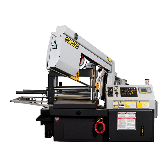
M-16A & M-20A PLC 500 E600 & PLC 100 E200
2003 Revision C
393060 December 2003
Effective T0503338
THANK YOU,
On behalf of everyone at HYD . MECH, I would like to thank and congratulate you on your decision to purchase a
HYD . MECH band saw.
Your new machine is now ready to play a key role in increasing the efficiency of your operation, helping you to reduce cut-
ting costs while boosting quality and productivity.
To ensure you are maximizing the power and versatility of your new HYD . MECH band saw, please take the time to famil-
iarize yourself and your employees with the correct operation and maintenance procedures as outlined in this manual.
We sincerely appreciate the confidence you have demonstrated in purchasing our product and look forward to building a
long and mutually beneficial relationship.
Thank-you.
HYD . MECH GROUP LIMITED
P.O. BOX 1030, 1079 Parkinson Road
Woodstock, Ontario Canada, N4S 8A4
Phone: (519) 539-6341
Service 1-877-237-0914
Sales 1-877-276-SAWS(7297)
Fax (519) 539-5126
e-mail, info@hydmech.com
01
Advertisement
Table of Contents
Troubleshooting

Related Manuals for Hyd-Mech M-20A PLC 100 E200


Summarization of Contents
Section 0: Safety Instructions
Summary and Mandatory Information
Overview of safety requirements, mandatory reading, and the importance of safety.
Basic Rules and Intended Use
Guidelines for machine operation, misuse exclusions, and liability.
Owner Responsibilities
Duties of the owner regarding manual accessibility, personnel, and machine condition.
Operator and Maintenance Personnel Responsibilities
Safety equipment checks, emergency stops, safe operation, and hazard label adherence.
Section 1: Installation
Lifting Instructions
Safe procedures and considerations for lifting the machine.
Foundation, Levelling, and Anchoring
Proper machine placement, levelling, and securing to the floor.
Blade Tension and Wiring Connections
Checking blade tension and performing power hook-up.
Cutting Fluid and Hydraulic Oil
Information on the type and maintenance of cutting fluid and hydraulic oil.
Head Height Check
Verifying and adjusting the head height for correct cutting alignment.
Section 2: Operation Instructions
Blade Basics and Control Console
Blade handling, speed control, and detailed overview of control panel functions.
PLC Operation Modes
Using the PLC for manual, automatic, single cut, and queue operations.
PLC System E200 Specifics
E200 PLC interface details, activation, and function key descriptions.
Cutting Setup and Parameters
Job setup, queues, kerf correction, feed, speed, and coolant flow.
Section 3: Maintenance and Troubleshooting
Safety Procedures
Lock-out procedures and general safety during maintenance tasks.
Blade and Guide Maintenance
Blade changing, tracking, guide adjustments, and work lamp maintenance.
System Maintenance
Lubrication, cleaning, and hydraulic system maintenance.
Troubleshooting Common Issues
Identifying and resolving common machine problems and faults.
PLC and System Calibration
PLC troubleshooting, parameters, I/O, and calibration procedures.
Section 4: Electrical System
General Electrical Information
Power connection, initial start-up, and earth grounding procedures.
Electrical Components Overview
Identification of key electrical components and their locations.
Component Lists
Detailed lists of electrical parts for various machine configurations and options.
Electrical Schematics
Wiring diagrams for different voltage ratings and options.
Section 5: Hydraulic System
Hydraulic Component Lists
Parts breakdown for M20 and M16 hydraulic assemblies.
Hydraulic Diagrams
Plumbing and schematic diagrams illustrating the hydraulic system.
Section 6: Mechanical System
Blade System Components
Blade brush, tension, and guide assemblies and their parts.
Vise and Control Assemblies
Pivot link, vise jaws, and encoder assemblies with their components.
Hydraulic and Drive Components
Hydraulic tank, pump, direct drive, and gearbox assemblies.
Conveyor and Related Assemblies
Conveyor, shuttle vise, doors, covers, and bundling assemblies.
Section 7: Options
Bundling Assembly
Components and details for the bundling vise option.
Roller and Vise Options
Vertical roller, outboard vise, and related mounting hardware.
Operational Options
Vise pressure, out of stock switch, laser sight, mist lubrication, and remote console.
Section 8: Specifications
M-20 Specifications and Layout
Dimensions, capacities, and physical layout of the M-20 model.
M-16 Specifications and Layout
Dimensions, capacities, and physical layout of the M-16 model.
Need help?
Do you have a question about the M-20A PLC 100 E200 and is the answer not in the manual?
Questions and answers