Table of Contents
Advertisement
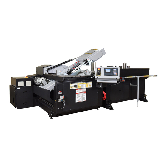
V18APC
393401
THANK YOU,
On behalf of everyone at HYD·MECH Group Limited, we would like to thank and congratulate you on your decision to
purchase a HYD·MECH bandsaw.
Your new machine is now ready to play a key role in increasing the efficiency of your operation, helping you to reduce cost
while boosting quality and productivity.
To ensure you are maximizing the power and versatility of your new HYD·MECH bandsaw, please take the time to
familiarize yourself and your employees with the correct operation and maintenance procedures as outlined in this
manual. Please keep this instruction manual for future reference in a known location and easily accessible to all users of
the device.
HYD·MECH offers a great variety of options, components, and features for its various models. Therefore, some of the
equipment described in this manual (various illustrations and drawings) may not be applicable to your particular machine.
The information and specifications provided in this manual were accurate at the time of printing. HYD·MECH reserves the
right to discontinue or change specifications or design at any time without notice and without incurring any obligation.
Thank you.
Hyd·Mech Group Limited
P.O. Box 1659, 1079 Parkinson Road
Woodstock, Ontario, N4S 0A9
Phone : (519) 539-6341
Service : 1-877-237-0914
Sales : 1-877-276-SAWS (7297)
Fax : (519) 539-5126
e-mail : info@hydmech.com
Printed MAY 2019
1
Advertisement
Table of Contents
Troubleshooting

Subscribe to Our Youtube Channel
Related Manuals for Hyd-Mech V18APC


Summary of Contents for Hyd-Mech V18APC
- Page 1 V18APC 393401 THANK YOU, On behalf of everyone at HYD·MECH Group Limited, we would like to thank and congratulate you on your decision to purchase a HYD·MECH bandsaw. Your new machine is now ready to play a key role in increasing the efficiency of your operation, helping you to reduce cost while boosting quality and productivity.
-
Page 3: Table Of Contents
TABLE OF CONTENTS SECTION 0 - SAFETY INSTRUCTIONS SUMMARY ............................0.1 BASIC RULES ..........................0.3 RESPONSIBILITIES OF THE OWNER ....................0.3 RESPONSIBILITIES OF THE OPERATOR AND MAINTENANCE PERSONNEL ......0.4 SAFETY HAZARD LABELS ......................0.6 SECTION 1 - INSTALLATION SAFETY PRECAUTIONS .........................1.1 V18 APC LIFTING AND SHIPPING....................1.2 LEVELLING THE V18 APC ......................1.3 REMOVE HEAD RESTRAINTS .......................1.4 INSTALLATION OF THE INFEED BASE..................1.4... - Page 4 MECHANICAL ASSEMBLY DRAWINGS & PARTS LIST: SEE PDF ON ATTACHED CD ....6.1 SECTION 7 - OPTIONS OPTIONAL ASSEMBLY DRAWINGS: SEE PDF ON ATTACHED CD ..........7.1 SECTION 8 - SPECIFICATIONS V18APC SPECIFICATIONS ......................8.1 V18APC LAYOUT LH (CANTED HEAD) ..................8.2 V18APC LAYOUT RH (CANTED HEAD) ..................8.4 SECTION 9 - WARRANTY WARRANTY .............................9.1...
-
Page 5: Section 0 - Safety Instructions
SECTION 0 - SAFETY INSTRUCTIONS SUMMARY All persons operating this machine must have read and understood all of the following sections of this Manual: Section 0 SAFETY Section 2 OPERATING INSTRUCTIONS However, as a memory aid, the following is a summary of the Safety Section. Put Safety First Mandatory Information –... - Page 6 FOREWORD Put Safety First! This Safety Section contains important information to help you work safely with your machine and describes the dangers inherent to bandsaws. Some of these dangers are obvious, while others are less evident. It really is important to PUT SAFETY FIRST. Make it a habit to consider the hazards associated with any action BEFORE you do it.
-
Page 7: Basic Rules
Manual, and When all operations and procedures are in compliance with this Manual. Hyd-Mech Group cannot accept any liability for personal injury or property damage due to operator errors or non-compliance with the Safety and Operating Instructions contained in this Manual. -
Page 8: Responsibilities Of The Operator And Maintenance Personnel
Define responsibilities Clearly define exactly who is responsible for operating, setting-up, servicing and repairing the machine. Define the responsibilities of the machine operator and authorize him to refuse any instructions by third parties if they run contrary to the machine’s safety. Persons being trained on the machine may only work on or with the machine under the constant supervision of an experienced operator. - Page 9 Clothing, jewellery, protective equipment Personnel operating or working on the machine must not wear un-restrained long hair, loose-fitting clothes and dangling jewellery. When operating or working on the machine, always wear suitable, officially tested personal protective equipment such as safety glasses and safety boots and any other equipment required by workplace regulations.
-
Page 10: Safety Hazard Labels
On Hyd-Mech machines the Master Disconnect Switch will be of one of four types: • Rotary switch mounted in electrical control cabinet door and inter-locked with door. • Rotary switch mounted on the side of the operator interface console. •... - Page 11 MOVING BANDSAW BLADE WILL CUT Do NOT operate with guard removed. Do NOT place hands or fingers near moving bandsaw blade. For blade changing, always follow the proper Blade Changing Procedure, as given in Section 3 of this manual. PINCH POINT Machine parts may move without warning, either because the machine is operating automatically, or because another person initiates the motion.
-
Page 12: Section 1 - Installation
SECTION 1 - INSTALLATION SAFETY PRECAUTIONS All safety precautions must be observed during installation, operation, or repair work on the V18 APC bandsaw machine. Inspect the machine thoroughly before power hook-up. Pay special attention to the electrical and hydraulic systems to ensure no damage was caused in shipping. -
Page 13: V18 Apc Lifting And Shipping
V18 APC LIFTING AND SHIPPING The shipping weight of the V18 APC main machine is 6000 lb. The machine can be lifted from the infeed side of the ma- chine by forklift as shown below. NOTE: The head restraint plate attached to the head and table must be removed before machine start up. -
Page 14: Levelling The V18 Apc
LEVELLING THE V18 APC It is important that the V18 APC be leveled and provision is made to secure the saw with concrete anchors to the floor. See foundation plan below - Note: There are 2 levelling bolts inside of the power pack compartment. Using a machinist’s level, level the saw from side to side and from front to back. -
Page 15: Remove Head Restraints
REMOVE HEAD RESTRAINTS Before start-up, remove the head support strut installed for shipping purposes to secure the head to the base. Replace the two 5/16 NC countersunk screws which fasten the wear-strip down. INSTALLATION OF THE INFEED BASE The shipping weight of the infeed is 3000 lb. The infeed can be lifted from the datum side by forklift as shown below. - Page 16 • Install the coolant side shields to both the infeed and outfeed side of the base. • Move the infeed base into position under the wear plate and line up the holes for the roll pins. Wear Plate Roll Pins...
- Page 17 • Use the leveling foot bolts to raise the infeed base towards the wear plate. Tighten the four socket head cap screws (390715) to mate the two pieces together. Level the infeed base with the machine by elevating the rear adjusting bolt. Once level has been achieved make sure that all levelling bolts are touching the floor.
- Page 18 Plumb the hydraulic hoses as per the photo below. Refer to the “Hydraulic Plumbing Diagram” found in the DWG • package CD NOTE: LH Infeed configuration shown 102A 101A • Fasten the conduit to the bracket with the provided nut. Connect the M12 connectors: C 19 : C 19-1 C2 23 : C 23...
-
Page 19: Shuttle Guard Installation
SHUTTLE GUARD INSTALLATION Refer to the “Perimeter Guard Assembly” drawings in the DWG package CD • • Assemble the moveable side leg to the infeed assembly • Assemble the datum side leg to the infeed assembly... - Page 20 • Assemble the rear guard tubes to the back of the infeed assembly • Assemble both the front guard and the hinged guard to the legs. A pulley is mounted on a bracket and attached to each rear corner of the safety guard. Fasten the three sides of the guard together at these brackets. Adjust the levelling bolts on each leg to ensure the guard is level.
- Page 21 • Pull cables C04 AND C 04A from the base and our through the 2 access holes in the infeed. Wire the switch. Refer to the wiring diagram provided (also located in the DWG package CD). Attach the spring/wire rope to the hinged guard’s eyebolt. •...
-
Page 22: Hydraulic Oil
HYDRAULIC OIL The V18 APC bandsaw is supplied with Texaco Rando HD46 oil. If it is necessary to change the oil to a different brand it is good practice to empty the hydraulic tank using a pump. Fill the hydraulic tank approximately 1/3 full with the new brand of oil and operate the saw through several cycles with maximum cylinder extension. -
Page 23: Blade Tension Check
BLADE TENSION CHECK When the machine is first started, the head must be swung to the vertical position so the blade position can be checked. Open the door at the top of the head and see that the blade has not moved off of the wheel. It should not be overhanging from the wheel more that 1/4”, if it is, then consult Blade Tracking information. -
Page 24: Section 2 - Operating Instructions
SECTION 2 - OPERATING INSTRUCTIONS Interface Operation Instructions PLC 500 CONTROL SYSTEM OPERATION OVERVIEW The PLC is a programmable logic controller that allows the operator to run the machine in both manual and automatic modes. The controls are divided into 2 main parts: - The Touchscreen and Key Pad - located on the right side of the panel. -
Page 25: Push Button Descriptions
PUSH BUTTON DESCRIPTIONS MANUAL MODE ONLY CONTROLS HEAD CONTROLS Pressing this key will retract the head backward and it will stop and hold its position if the key HEAD RETRACT is released. Pressing this key will advance the head forward and it will stop and hold its position if the key HEAD ADVANCE is released. - Page 26 The SERVICE MODE allows the user to adjust the various PLC parameters. The user will be SERVICE MODE prompted for a password. Contact Hyd-Mech Group Limited to access this mode. Pressing this key will cause the LASER to turn on or off. The red LED indicates that the LASER ON / OFF LASER will be on.
-
Page 27: Control System Operating Instructions
CONTROL SYSTEM OPERATING INSTRUCTIONS OPTIONAL EQUIPMENT SHOWN MACHINE START UP Reset the E-Stop by pulling out the red mushroom button. There is a short delay to allow the machine software to load. Press the machine start button to start the hydraulics. If the head is not at 90 degrees then the display screen will look as follows. -
Page 28: Manual Mode
The following must be done to activate the cutting modes: The head must be fully retracted. Then the head must pass 90 degrees. The approach can be done in fast speed, but the passing of 90 must be done in slow. After the above points are achieved the screen will change to manual mode. -
Page 29: Kerf Correction For Angle Cutting (Manual Mode)
KERF CORRECTION FOR ANGLE CUTTING (Manual Mode) When making mitered cuts, the part length must be set longer than the desired length by an amount called the KERF CORRECTION or the kerf value must be adjusted. This is due to the fact that the PLC will not account for a difference in the kerf value at various angles. -
Page 30: Parameters
PARAMETERS The parameters can be accessed by pressing the service mode button on the panel. These parameters can be changed without a password. 1. COOLANT ON WHEN BLADE RUN: __ / AND HD. AD In Automatic Mode - Allows the coolant to flow whenever the blade is running or when the blade is running and the head advances. - Page 31 From this screen all the other parameters can be viewed, but a password will be needed to change any settings. See “PLC Parameters” at the end of this section to view the list. HYD MECH service department should be contacted before attempting to change any of these settings.
- Page 32 PARAMETER DEFINITION MATERIAL INFEED Defines the infeed side of the machine. MACHINE TYPE Defines the style of machine. MACHINE MODEL Defines model. SHUTTLE CONSTANT Specifies linear distance of shuttle movement in inches per one pulse. SHUTTLE FULL STROKE Maximum usable shuttle travel. SHUTTLE SLOW SPEED Minimum shuttle speed constant.
-
Page 33: Automatic Operation
AUTOMATIC OPERATION To enter AUTO MODE, the Infeed Vise must be in the closed position. When the AUTO MODE push button is pressed, the red indicator will come on. The screen will change to the JOB display window as shown below and will be ready for editing or starting a new job. - Page 34 Step 2. After the job # has been assigned, select the desired cut profile from the 9 different cut profiles provided on the selection bar illustrated on the touch screen. Once the desired profile has been selected, the geometry and required di- mensional inputs of the cut profile will change on the job display window to that of the selected profile.
- Page 35 STEP 8 STEP 7 STEP 9 Step 7. To ensure that no jobs from the previous queue have been programmed into this queue. It is recommended that the previous job queue be cleared before programming the new job queue. This is done by selecting the “CLEAR QUEUE”...
- Page 36 Step 10. Once the queue has been initiated the Auto Mode Status display window will appear and the machine will begin positioning itself for its first cut. If the blade is not running, the display will prompt you to start the blade. Press the “Blade Start”...
-
Page 37: Hydraulic Feed Control
HYDRAULIC FEED CONTROL The Hydraulic Feed Control is located next to the control panel. These controls allow independent control of Feed Force and Feed Rate. Feed Force Knob Used to set Feed Force Limit (counterclockwise rotation to increase and clockwise rotation to decrease). -
Page 38: Cutting Solids
CHART EXAMPLE #1 We will use the parameters chart to set up the saw for cutting 8” (200mm) Diameter #1045 Carbon Steel. STEP 1 - DETERMINE EFFECTIVE MATERIAL WIDTH - W (inches) or (mm) Effective material width, W (in.) for most common shapes of materials, is the widest solid part of the material to be in con- tact with blade during cutting. - Page 39 STEP 3 - DETERMINE OPTIMUM BLADE PITCH - TEETH PER INCH (T.P.I.) Selecting a blade with proper tooth pitch is important in order to achieve optimal cutting rates and good blade life. For cutting narrow or thin wall structural materials a fine blade with many teeth per inch (T.P.I.) is recommended. For wide materials a blade with a coarse pitch should be used.
- Page 40 In Example #1 8” (200mm) diameter #1045 Medium Carbon Steel solid bar is to be cut. • • On the graph above find the Medium Carbon Steel Curve which represents the optimum blade speeds for 1045 Carbon Steel. On the horizontal axis (effective material width axis) find number 8 which represents effective material width of an •...
- Page 41 FEED RATE is the speed at which the blade travels through the work-piece. The FEED RATE Knob controls FEED RATE of the blade travel in the range 0 to 15 in/min (380mm/min). The FEED RATE should be adjusted only in one direction (from “O” to required value). If you go too far, go back to “O” and come back up.
-
Page 42: Additional Cutting Setup Examples
ADDITIONAL CUTTING SETUP EXAMPLES EXAMPLE # 2 Material Round Steel Tube SAE 4320 - Hardened to 35 RC (325 Bhn) Dimensions - 6” O.D. x 4” I.D. (150mm O.D. x 100mm I.D.) STEP I Effective Material Width: 4 1/2” (.75 X 6) 114mm (19 x 6) STEP 2 Feed Force limit setting for 6”... -
Page 43: Coolant Flow
COOLANT FLOW A generous flow of coolant should be applied in order to increase production and blade life. The machine is provided with an indepen- dently controlled coolant spout. This spout should always flood the blade with coolant. Slight adjustment may be required when changing the blade speed. -
Page 44: Head Swing Brake
HEAD SWING BRAKE The brake assembly can be accessed by removing the brake cover. The brake should be adjusted with the head swing either to the extreme left or right. (Make sure system pressure is set properly). Maintain the machine in swing mode (ei- ther left or right). -
Page 45: Section 3 - Maintenance And Trouble Shooting
SECTION 3 - MAINTENANCE AND TROUBLE SHOOTING LOCK-OUT Purpose: To prevent injury to workers caused by unexpected start-up of machines being worked on, Where the starting of a machine or device may endanger the safety of a worker. a) Control switches or other control mechanisms shall be locked out, b) Other effective precautions necessary to prevent such starting shall be taken. -
Page 46: Blade Change Procedure
BLADE CHANGE PROCEDURE Wear safety glasses, gloves, and a long sleeve shirt for protection when handling bandsaw blades during blade change. NOTE THAT GLOVES SHOULD NEVER BE WORN NEAR A RUNNING BANDSAW BLADE. When handling new blades, or ones that will be re-used, it is important to keep the teeth out of contact with concrete floors. -
Page 47: Blade Installation
BLADE INSTALLATION NOTES ABOUT NEW BLADES: • It is helpful to have two people to install a new blade. A new blade will come folded into a compact coil. Follow the blade manufacturer’s instructions for safely unfolding • blade. • The blade must be installed with the teeth facing out towards the front of the saw where it passes around the wheels, and with the teeth in the cutting area pointing towards the drive wheel. -
Page 48: Idler Wheel Adjustment
If the brush gets worn to approximately 70% of its original 3” diameter it should be replaced. A brush may be purchased from your HYD-MECH dealer. Blade brush & adjusting screw (circled). -
Page 49: Head Forward Limit Setting
HEAD FORWARD LIMIT SETTING The Head Forward Limit is factory set and under normal operating conditions should not need to be reset. TO SET LIMIT: If adjustment of the Shaft Collar is necessary, the Head Forward Limit is an assembly on the vise cylinder rod. - Page 50 PLUG One of 4 linear bearing block grease nipples. There is one at each corner of the head carrier cover. Remove round plas- tic plugs to gain access to the two back grease nipples Bearing Block ( X4 ) Vise Ways ( X2 ) Anti tip roller ( X2 ) INFEED ASSEMBLY Linear bearing block...
-
Page 51: Hydraulic Maintenance
To access the two idler wheel slide as- sembly grease nipples the wheel must be removed. A flexible grease gun hose fitting is required to apply the with a 45 grease. HYDRAULIC MAINTENANCE There are four items of routine maintenance associated with the hydraulic system of the V18 APC. With proper mainte- nance the hydraulic system of the V18 APC should provide years of reliable service. -
Page 52: Trouble Shooting Guide
TROUBLE SHOOTING GUIDE Most problems which may occur have one of the relatively simple solutions which appear in this section. If the solution is not found here, contact the Hyd·Mech Distributor from whom you purchased your bandsaw. They have trained field ser- vice personnel who will be able to rectify the problem. - Page 53 Blade tension is determined by system 2 Blade comes off wheels. 2a. Blade tension is insufficient. pressure. Check. (Extended head, check if blade tension gauge reads 650 psi). Have tracking set to blade specification. 2b. Blade tracking out of adjustment. Blade tension is determined by system 3 Blade stalls while cutting.
-
Page 54: V18 Apc Electrical
SECTION 4 - ELECTRICAL V18 APC ELECTRICAL The electrical schematics on CD show some components labeled as TB1 to TB6 and these components are physically mounted on din rails. The illustration below shows the location of the Din rails with the installed components and the des- ignated TB number. - Page 55 From page 1, it can be seen that TB1 has the High Speed Counter, PLC and terminals mounted to it. For example, if the electrical schematic shows a terminal, described as This indicates that the terminal is located on din rail TB1 and is terminal #2. This would indicate that the terminal is mounted on TB1 and is terminal #5.
- Page 56 A close up view of TB2 is shown. Page 1 shows the position of TB2 in the control panel. For example, if the electrical schematic shows a terminal, described as This indicates that the terminal is located on din rail TB2 and is terminal #3. This would indicate that the terminal is mounted on TB2 and is terminal #6.
- Page 57 A close up view of TB3 is shown. Page 1 shows the position of TB3 in the control panel. For example, if the electrical schematic shows a terminal, described as This indicates that the terminal is located on din rail TB3 and is terminal #7. This would indicate that the terminal is mounted on TB3 and is terminal #16.
- Page 58 TB5 contains fusible terminals and a power supply. These are identified on the schematic as FU3 to FU8 and PWS for the power supply.
- Page 59 TB6 Contains ground terminals (partially visible) mounted either side of the contactors MS1M & MS2M and are indicated on the schematic as TB6 & The mounting location in the control panel is shown on page 1...
- Page 60 TB4 is located in the HMI panel (Human Machine Interface). This houses the selector switches and push buttons. As in the main panel the same concept applies, for example: This indicates that the terminal is located on din rail TB4 and is terminal #25.
- Page 61 DT (Device Tag) The remainder of the components in the control panel are labeled and are referred to in the documentation under the DT heading. For example: DT, CR4 is the control relay labeled CR4. DT, LS2 is the limit switch for Head Advance function. DT, MS 1M is the contactor labeled MS 1M.
-
Page 62: Section 5 - Hydraulic System
SECTION 5 - HYDRAULIC SYSTEM The V18 APC hydraulic system does not require any special work on a new machine before its start-up. The hydraulic tank is filled with Texaco Rando HD 46 oil and all machine functions have been tested at the factory to ensure the proper operation upon initial start-up. -
Page 63: Gland Assemblies
CYLINDER ASSEMBLIES GLAND ASSEMBLIES CYLINDER DIAMETER O RING BACKUP GLAND LOADED WIPER O RING U CAP 2.0” 362960 362785 CS20-GL-01A 362830 363330 2.5” 362970 362790 CS25-GL-01B 362815 363335 3.0” 362985 362795 CS30-GL-01A 362815 363335 3.5” 362995 362800 CS35-GL-01A 362835 363340 4.0”... -
Page 64: Hydraulic Schematic And Plumbing Diagram
HYDRAULIC SCHEMATIC AND PLUMBING DIAGRAM: SEE PDF ON ATTACHED CD... -
Page 65: Section 6 - Mechanical Assemblies
SECTION 6 - MECHANICAL ASSEMBLIES MECHANICAL ASSEMBLY DRAWINGS & PARTS LIST: SEE PDF ON ATTACHED CD... -
Page 66: Section 7 - Options
SECTION 7 - OPTIONS OPTIONAL ASSEMBLY DRAWINGS: SEE PDF ON ATTACHED CD... -
Page 67: Section 8 - Specifications
SECTION 8 - SPECIFICATIONS V18APC SPECIFICATIONS V18APC-60 BANDSAW SPECIFICATIONS HEAD CANT STRAIGHT HEAD 3 DEGREE at 90º rectangular 18" x 23" (457mm x 584mm) 18" x 22" (457mm x 558mm) at 90º round 18" (457mm) with tall vise insert option 18"... -
Page 68: V18Apc Layout Lh (Canted Head)
V18APC LAYOUT LH (CANTED HEAD) -
Page 70: V18Apc Layout Rh (Canted Head)
V18APC LAYOUT RH (CANTED HEAD) -
Page 72: Section 9 - Warranty
SECTION 9 - WARRANTY WARRANTY Hyd-Mech Group Limited warrants parts/components on each new V18APC bandsaw to be free from failure resulting from defective material and workmanship under proper use and service for a period of two years following the date of shipment to the user.
Need help?
Do you have a question about the V18APC and is the answer not in the manual?
Questions and answers