Table of Contents
Advertisement
Quick Links
Advertisement
Table of Contents

Subscribe to Our Youtube Channel
Related Manuals for Hyd-Mech DM-1215


Summary of Contents for Hyd-Mech DM-1215
- Page 1 USE AND MAINTENANCE MANUAL DM−1215 YEAR OF MANUFACTURE: ______________...
-
Page 3: Ce Conformity Declaration
Translation of the original instructions ”CE” CONFORMITY DECLARATION (according to EEC MACHINES DIRECTIVE 2006/42/CE annex II A) The manufacturer: MEP S.p.A. Via Enzo Magnani, 1 61045 Pergola (PU) ITALIA Tel. 072173721−Fax 0721734533 ereby declares that the bandsawing machine: Machine Type: SAWING MACHINE Machine model: DM- 1215 Serial number:... - Page 5 Introduction and technical specifications ... . . 1−1 Foreword ........1−1 Machine presentation .
- Page 6 Clamping the work piece in the vice ....5−3 Rapid vice positioning ......5−4 Rapid vice translation .
- Page 7 Orthogonality of the blade ......7−11 Rotation axis control ......7−14 Maintenance and choice of consumables .
- Page 8 Troubleshooting blade and cutting problems ... 10−1 Troubleshooting machine faults ..... 10−8 Accessory Installation .
-
Page 9: Machine Presentation
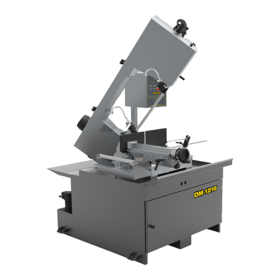
EEC safety standards. The DM-1215 is structurally rigid, silent and safe: it produces a minimum of waste (1.2 mm) while its great versatility makes it suitable for cutting various materials such as stainless steel light alloys, aluminium, copper and bronze at high speed and with high precision. -
Page 10: Machine Specification
−3 Kg/l) where 1 Kg/min. = 772 Nl/min. LUBRICANT/COOLANT FLUID AND OIL Oil for transmission box capacità Kg 0,32 Oil for Cut Control System cylinder capacità Lt Lubricant/coolant fluid (oil concentration 5-6%) capacità Lt 1−2 Use and maintenance manual DM-1215... -
Page 11: Spindle Motor
VICE Vice max. opening SPINDLE MOTOR No.of poles Current (Volts) Absorption Power (Kw) Band saw (Amps) speed 139-240 14,8/8,6 2,20 1720 15/115 mt/min Stator wound with enamelled copper wire, class H 200°C. Class F insulation (limit temperature TL 155°C). IP 55 protection rating (total against contact with live parts, water sprayed from all directions, with shaft oil seal). - Page 12 Dimensions MACHINE INSTALLED Work table height Weight 2000 2000 1300 PACKED WEIGHT Wooden cage and pallet Wooden pallet 1−4 Use and maintenance manual DM-1215...
- Page 13 Functional parts Ó Ó Ó Ó Ó Ó Ó Ó Ó Ó Ó Ó Ó Ó Ó Ó Ó Ó Ó Ó Ó Ó Ó Ó Ó Ó Ó Ó Ó Ó Ó Ó Ó Ó Ó Ó Ó Ó Ó Ó Ó Ó Ó...
-
Page 14: Cutting Head
The vice is approached to the cutting material manually by handwheel and the locking is by pneumatic cylinder. Slideway Turntable Handwheel Vice support (lead nut) Fixed platform 2−2 Use and maintenance manual DM-1215... -
Page 15: Control Panel
Control Panel The control panel has a protection rating of IP 54 and contains the electrical equipment. Access is gained by removing the screws fastening a safety panel, while the operator's safety is guaranteed by a key-operated safety switch, designed to prevent any intentional interference with the unit. In order to remove the panel from its mounting, the main switch has to be shifted to 0 (OFF), which automatically cuts off the electrical supply. - Page 16 Coolant spray gun Tank cover Electric pump housing Lubricant/coolant tank Swarf collection drawer On the right side there is the refrigerant fluid gun and the removable shaving collector drawer. 2−4 Use and maintenance manual DM-1215...
-
Page 17: Use Of The Machine
Ó Ó Ó Ó Ó Ó Ó Ó Ó Ó Ó Ó Ó Ó The DM-1215 has been designed and produced in accordance with European standards. For the correct use of the machine we recommend that the instruc tions contained in this chapter are carefully followed. -
Page 18: General Recommendations
The installation of the earthing system must comply with the requirements set out in EN STANDARD 60204-1:2010. OPERATOR POSITION The position of the operator controlling machine operations must be as shown in the diagram below. 3−2 Use and maintenance manual DM-1215... -
Page 19: Recommendations To The Operator
Recommendations to the operator Always wear proper goggles or protective glasses. Do not use the machine without the guards in position. Replace the poly carbonate windows , if subject to corrosion Do not allow hands or arms to encroach on the cutting zone while the machine is in operation. - Page 20 Warning: if the blade jams in the cut, press the emergency stop push- button immediately. If this does not free the blade, slowly loosen the vice, remove the piece and check the blade or blade teeth for breakage. Replace the blade if necessary. 3−4 Use and maintenance manual DM-1215...
-
Page 21: Machine Safety Devices
EEC Committee in the directives regarding safety of machinery, health and safety at work, personal protection and safeguarding of the environment. These standards have been applied to the DM-1215 band saw. Reference standards MACHINE SAFETY EEC MACHINES DIRECTIVE 2006/42/CE ;... -
Page 22: Protection Against Accidental Contact With The Blade
24 Vac Control voltage for actuators, in accordance with chapter 6 or Euro pean Standard “Control and indication circuits”, paragraph 2 “Control Cir cuits” sub-section 1 “Preferential voltage values for control circuits”; 3−6 Use and maintenance manual DM-1215... - Page 23 ...Emergency devices applicable to the DM-1215: 1. Emergency stop: a non-return mushroom-head pushbutton, colour red on yellow background, is located on the control panel of the machine. To release the pushbutton, the actuator must be rotated 45°.
-
Page 24: Noise Level Of The Machine
80 mm diameter solid tube in chromed stainless steel Description Bimetal band 3440x27x0,9 S.GLB Z 10/14 Test 3rd Mean sound level (Leq) 71,95 dB(A) Environmental correction (K) 3,84 dB(A) Results Peak sound power (Lw) 83,11 dB(A) 3−8 Use and maintenance manual DM-1215... -
Page 25: Electromagnetic Compatibility
The following text contains a list of the applied standards and the results of the electromagnetic compatibility testing of machine model DM-1215; Test report no. 170201. Emissions EN 61000−6−4 (2002) Electromagnetic Compatibility (EMC) −... - Page 26 EN 50370−2:2003 Electromagnetic compatibility (EMC) − Product family standard for machine tools − Part 2: Immunity The EUT is deemed to fulfil the immunity requirements without testing, because it contains no electonic control circuitry. 3−10 Use and maintenance manual DM-1215...
-
Page 27: Packaging And Storage
Machine installation Ó Ó Ó Ó Ó Ó Ó Ó Ó Ó Ó Ó Ó Ó Ó Ó Ó Ó Ó Ó Ó Ó Ó Ó Ó Ó Ó Ó Ó Ó Ó Ó Ó Ó Ó Ó Ó Ó Ó Ó Ó Ó Ó... - Page 28 To install the machine, first remove the packing, paying particular attention not to cut any electric wires or hydraulic hoses; if necessary use pliers, a hammer and a cutter. Open crate in the illustrated order: 4−2 Use and maintenance manual DM-1215...
- Page 29 1. remove nails and lift the top of the cage; 2. remove nails and lower walls; 3. remove heat-shrink covering; 4. remove the straps; 5. remove nails from pallet securing planks and remove planks; 6. remove the front panel and insert fork tines. To locate the machine in the workplace, the machine dimensions and necessary operator working space, including the spaces laid down in safety standards, must be taken into account.
-
Page 30: Anchoring The Machine
90% lighting: not less than 500 Lux. The machine is already protected against voltage variations, but will only run Warning trouble−free if the variations do not exceed ± 10%. 4−4 Use and maintenance manual DM-1215... - Page 31 Check list Before starting installation, check that all the accessories, whether standard or optional, supplied with the machine are present. The basic version of the DM-1215 2-SPEED machine is supplied complete with: CHARACTERISTICS STANDARD OPTIONAL Ergonomic and functional pedestal that allows total recovery of the refrigerant...
-
Page 32: Connection To The Power Supply
" set the blade tension to 900 kg; " make sure the cover is properly closed: at the back of the cutting head there is a bayonet limiter for correct cover closure; 4−6 Use and maintenance manual DM-1215... - Page 33 " make sure that the machine is not in an emergency condition (red mush room-head pushbutton released); " select cutting speed using the inverter. Check that the cutting head descent speed adjuster is at zero. Warning " operate the jog button on the manual head control lever; "...
- Page 35 Description of the control panel The components of the DM-1215 control panel are shown in the diagram below. Each arrow has a number which corresponds to the descriptions that follow. 5−1...
- Page 36 Selector to activate the laser or the lamp for illumination of the cutting area. 8 − MANUAL OR GRAVITY−FEED CYCLE SELECTOR Select manual or gravity-feed cutting cycle. 9 − SPRAY MIST BUTTON (OPTIONAL) Activates or deactivates the band spray mist. 5−2 Use and maintenance manual DM-1215...
- Page 37 Basic instructions for carrying out a cutting operation cycle Manoeuvring the cutting head Cutting head movement is facilitated by perfect balancing of the head weight, thanks to the traction force exerted by the two return springs located at the back of the machine.
-
Page 38: Rapid Vice Positioning
The width of the cut is determined by the longitudinal section of the workpiece, so that only the part of the blade required to make the cut is actually exposed. 5−4 Use and maintenance manual DM-1215... -
Page 39: Preliminary Check List For Cutting Operation
" Position the workpiece on the work table in proximity to the blade down stroke trajectory and clamp it in the vice; " Slacken the ratchet lever on the sliding shaft of the front blade guide head. " Position the mobile front guide head near the workpiece so that the down stroke trajectory exceeds the mobile vice jaw. -
Page 40: Manual Operating Cycle
" Clamp the workpiece in the vice. " Select the cut using the Inverter. " Grip the head control lever and start the blade rotating by pressing the mi 5−6 Use and maintenance manual DM-1215... - Page 41 croswitch on the handgrip; the downstroke speed of the head is manually con trolled by the operator. " The motor starts up and sets the blade in rotary motion; the lubricant/coolant pump starts up at the same time. " At the end of the cutting operation, the head can be raised. "...
- Page 42 Gravity-feed and then press microswitch on the handgrip to start up blade rotation. " The operating head will now perform cutting until it reaches HDL (Head Downstroke Limit) at which point the motor will stop. 5−8 Use and maintenance manual DM-1215...
-
Page 43: Angled Cuts
Angled cuts The machine can make angled cuts from 60° left to 45° right. Reference stops are mounted on the sides of the turntable to facilitate rapid 0° , 45° and 60° cuts to the left and 45° cuts to the right. Angled cuts 45°... - Page 44 Angled cuts 60° to the left " Undo the bush on the 45° left reference stop, as illustrated in the figure be low, using a 36 mm wrench; " Remove the 45°reference stop; " slacken the turntable lock/release lever; 5−10 Use and maintenance manual DM-1215...
- Page 45 " pull the eccentric pin knob towards you (0° reference stop) and rotate slightly to raise it; " swing the head from left to right until it is positioned at the required angle, as indicated by the graduated scale on the turntable; "...
- Page 46 " rotate the head from right to left, till reaching the wished cant which is dis played by the grading on the rotating platform. " Relock the turntable lock/release lever; " make the cut in the required operating mode, following the preliminary safety instructions set out in this chapter. 5−12 Use and maintenance manual DM-1215...
- Page 47 Ó Ó Ó Ó Ó Ó Ó Ó Ó Ó Ó Ó Ó Ó This chapter contains functional diagrams and exploded views of the DM-1215. This document is intended to help in identifying the location of the various components making up the machine, giving information useful in carrying out repair and maintenance operations;...
- Page 48 Indications of the model of machine Indication of the Indications of the date production page number started MARIO ROSSI Identification of the designer Identification of the Reference Standard 6−2 Use and maintenance manual DM-1215...
- Page 49 Each component in the wiring diagram is identified by a unique alphanumeric identification code, in compliance with regulations: This symbol identifies the wire The wire is identified by the code -W4 with its relative number and colour These symbols, known as potentials, are used to The motor is identified by the code -M1 provide page references: the first number indi...
-
Page 50: Identification Of The Appliance
Devices not specified in this table Protective Devices Lightning protectors Arrestors Instant action current thresh old protector Delayed action current thresh old protector Instant and delayed action current threshold protector Fuse Voltage threshold protector 6−4 Use and maintenance manual DM-1215... - Page 51 LETTER TYPE OF COMPONENT EXAMPLES IDENTIFICATION OF THE APPLIANCE Generators, feeders Rotating generators Crystal oscillators Accumulator battery Rotating or static frequency converter Power feeder Signaling Devices Buzzer Optical signal, indicator light device Relays, Contactors Instant all or nothing relays or instant contactors Bistable relays or interdepen...
- Page 52 Connector bar Test plug Plug Socket Terminal connector band Electrically operated mechanical Electromagnet appliances Electromagnetic brake Electromagnetic clutch Magnetic table spindle Electromagnetic valve Transformers, impedence Line equalizer adapters, equalizers, band lim Compresser iters Crystal filter 6−6 Use and maintenance manual DM-1215...
- Page 53 Standardised Wiring Diagrams Diagrams, exploded views and replace− 6−7...
- Page 54 6−8 Use and maintenance manual DM-1215...
- Page 55 Diagrams, exploded views and replace− 6−9...
- Page 56 6−10 Use and maintenance manual DM-1215...
- Page 57 Diagrams, exploded views and replace− 6−11...
- Page 58 6−12 Use and maintenance manual DM-1215...
- Page 59 Diagrams, exploded views and replace− 6−13...
- Page 60 6−14 Use and maintenance manual DM-1215...
- Page 61 Diagrams, exploded views and replace− 6−15...
- Page 62 6−16 Use and maintenance manual DM-1215...
- Page 63 Diagrams, exploded views and replace− 6−17...
- Page 64 6−18 Use and maintenance manual DM-1215...
- Page 65 Diagrams, exploded views and replace− 6−19...
- Page 66 6−20 Use and maintenance manual DM-1215...
- Page 67 Diagrams, exploded views and replace− 6−21...
- Page 68 6−22 Use and maintenance manual DM-1215...
- Page 69 Diagrams, exploded views and replace− 6−23...
- Page 70 6−24 Use and maintenance manual DM-1215...
-
Page 71: Front Flywheel Assembly
Front flywheel assembly 6−25... - Page 72 TCEI 6 X 10 SCREW (010.7867) 1,000 010.7868 VITE TCEI 6 X 12 (010.7868) TCEI 6 X 12 SCREW 1,000 010.7870 VITE TCEI 6 X 16 (010.7870) TCEI 6 X 16 SCREW (010.7870) 2,000 6−26 Use and maintenance manual DM-1215...
- Page 73 Code Description Description Quantity 010.7871 VITE TCEI 6 X 20 (010.7871) TCEI 6 X 20 SCREW (010.7871) 1,000 010.7875 VITE TCEI 6 X 40 (010.7875) TCEI 6 X 40 SCREW (010.7875) 1,000 010.7890 VITE TCEI 8 X 12 (010.7890) TCEI 8 X 12 SCREW (010.7890) 2,000 010.7893 VITE TCEI 8 X 20 (010.7893)
-
Page 74: Motor Flywheel Assembly
Motor flywheel assembly 6−28 Use and maintenance manual DM-1215... - Page 75 Code Description Description Quantity 001.4228 ARCHETTO SEZIONE PULEGGIA MOT- BOW SH 320/330 WITHOUT REDUCER 1.000 RICESH 332 ”15” MOD.1420 001.4230 PULEGGIA MOTRICE SH 332 ”15” MOTOR WHEEL SH 332 ”15” 1.000 MOD.1422 007.3770 SUPPORTO TESTINA POSTERIORE SH REAR HEAD SUPPORT SH 320 60 1.000 320 60 −SH 332 007.3813...
- Page 76 043.0229 RIDUZIONE MF 1/4 − CL 2520 MF 1/4 − CL 2520 REDUCTION 1.000 043.0260 TAPPO TTE4 1/4 − CL 2611 1/4 TAP TTE4 1.000 043.0652 RUBINETTO 1/4 F.M. 1/4 F. M. TAP 1.000 6−30 Use and maintenance manual DM-1215...
-
Page 77: Cutting Head Cover
Cutting head cover 6−31... - Page 78 2.000 COPERCHIO SWITCH 016.3366 CARTER POSTERIORE TRAVE SH 382 REAR CARTER 2.000 019.5370 FASCETTA LEGRAND ART.31900 LEGRAND CLAMP ART.31900 2.000 034.1107 VOLANTINO O 30 M6 X 20 O 30 M6 X 20 HANDWHEEL 2.000 6−32 Use and maintenance manual DM-1215...
-
Page 79: Vice Assembly
Vice assembly 6−33... - Page 80 1.000 034.0205 VOLANTINO VPRA/125 MR SH VPRA/125 HANDWHEEL SH + PH 1.000 282−292−320−330PH 211−1/261−1 034.1002 LEVA A SCATTO 10 MA LEVER 10 MA 1.000 034.1003 LEVA A SCATTO 12 MA LEVER 12 MA 1.000 6−34 Use and maintenance manual DM-1215...
-
Page 81: Base Assembly
Base assembly 6−35... - Page 82 TE FFF GALVANISED 3/4 JOINT 1.000 043.0277 NIPPLO CONICO ZINCATO 3/4 GALVANISED 3/4 CONICAL NIPPLE 1.000 043.0351 GUARNIZIONE 3/4 3/4 GASKET 1.000 043.0654 RUBINETTO M/F 3/4 CL 6310 M/F 3/4 CL 6310 TAP 1.000 6−36 Use and maintenance manual DM-1215...
- Page 83 Control panel 6−37...
- Page 84 PANNELLO COMANDI INFERIORE LOWER CONTROL PANEL DM 12 1.000 DM 12 034.1169 MANOPOLA REGOLAZIONE FEED RATE KNOB (W/ SEMICIRCLE 1.000 MONOGIRO HOLE) 043.0594 REGOLATORE IDRAULICO HYDRAULIC REGULATOR SH−CB− 1.000 MONOGIROUNIDIREZIONALE SH CB−TI (BAFFO A) 6−38 Use and maintenance manual DM-1215...
- Page 85 Fixed work table and turntable 6−39...
- Page 86 RONDELLA GROOVER M8 M8 SPRING WASHER 1.000 010.7674 RONDELLA SPESSORE THICKNESS WASHER DIAM. 10,5 X 30 1.000 DIAM.10,5X30(010.7674) 010.7759 SPINA ELASTICA DIAM. 3 X 16 ELASTIC PIN DIAM. 3 X 16 (010.7759) 1.000 (010.7759) 6−40 Use and maintenance manual DM-1215...
- Page 87 Code Description Description Quantity 010.7761 SPINA ELASTICA DIAM. 4 X 20 ELASTIC PIN DIAM. 4 X 20 (010.7761) 1.000 (010.7761) 010.7767 SPINA ELASTICA DIAM. 6 X 35 A SPIRA- ELASTIC PIN DIAM. 6 X 35 2.000 010.7830 VITE BUTON 5 X 10 (010.7830) 5 X 10 BUTON SCREW (010.7830) 1.000 010.7870...
-
Page 88: Cylinder Unit
Cylinder unit 6−42 Use and maintenance manual DM-1215... - Page 89 Code Description Description Quantity 007.3695 STAFFA AGGANCIO MOLLA E CILIN- SPRING AND CYLINDER SHANK BRAC- 1.000 DRO SH 332 KET SH 332 010.0949 MOLLA RICHIAMO TESTA SH 320−332 HEAD RETURN SPRING 1.000 010.1103 FORCELLA 16 X 1,5 16 X 1,5 FORK 1.000 010.1412 STAFFA SUPPORTO CILINDRO SH 332...
- Page 90 Laser and lamp group 6−44 Use and maintenance manual DM-1215...
- Page 91 016.2778 STAFFA LAMPADA LED BRACKET LED LAMP 1.000 016.3620 STAFFA SUPPORTO LASER/LAM LASER / LAMP SUPPORT BRACK 1.000 PADA DM-1215 022.1191 LASER MOD.5OEM 24V OTTICA LASER MOD.5OEM 24V 1.000 ARIGA CON M8 MASCHIO PANNEL LO SENZA CAVO 022.3255 FARO LED 4,2W 16/36 VCC 330LM LED LIGHT 4,2W 16/36 VCC 330LM 1.000...
- Page 93 Ó Ó Ó Ó Ó Ó Ó Ó Ó Ó Ó Ó Ó Ó The adjustment operations for correct use of the DM-1215 mechanical, pneu matic and hydraulic systems are described in this chapter. These instructions will enable you to “customise” your machine to suit the type of cuts you want, optimising the time required to complete them.
- Page 94 " repeat the operation on the gib grub screws on all the slideway grub screws; " at the end of the operation, use the handwheel to move the slideway back and forth, identifying the zones where the grub screws exert greater pressure on the gib. 7−2 Use and maintenance manual DM-1215...
-
Page 95: Blade Tensioner Slide Play Adjustment
Cutting head Blade tensioner slide play adjustment To reduce the play which develops over a period of time between the blade tensioner slide and the slide gibs, the grub screws separating the gibs from the slide must be adjusted as follows: "... -
Page 96: Adjusting Operating Head Travel
" Loosen the end run support screw fasteners and move it forward and back ward in the slots to near it or distance it from the contact point. " Tighten the screws when the optimal position has been obtained. 7−4 Use and maintenance manual DM-1215... -
Page 97: Blade Guide Parts
Blade guide parts Band saw blades offer enormous advantages to cutting applications, without requiring any special skills by the operator. A description follows of the blade guide adjustments required to ensure correct operation of the saw. Blade guide heads The first blade adjustment involves adjustment of the heads. The blade guide heads comprise the blade guide plates which ensure correct longitudinal align... - Page 98 " open the front blade guard by undoing the fixing screw and rotating it as illus trated in the figure below; " wear protective gloves when making this adjustment; " make sure there is a small amount of play between the blade and guide plate inserts; 7−6 Use and maintenance manual DM-1215...
- Page 99 " if the amount of play is not sufficient for the blade to run smoothly, adjust the locking torque of the two grub screws with an Allen key; " replace any worn plates by removing the plate fixing screw; " repeat the above sequence of steps on the rear blade guide head; "...
-
Page 100: Tool Change
" open the cutting head cover by unscrewing the two knobs and hooking it onto the galvanised lever on the back of the head; " open the front blade guard by undoing the fixing screw and rotating it as illus trated in the figure below; 7−8 Use and maintenance manual DM-1215... - Page 101 " remove the rear blade guard by undoing the two fixing screws using an Allen key; " wear protective gloves when changing the blade; " remove the worn blade by sliding it off the flywheels and front and rear heads; "...
-
Page 102: Blade Perpendicularity
If the point of contact is at the upper part, slacken the TCEI screw (A') and tighten grub screws (B') equally until the blade is perpendicular to the square. 7−10 Use and maintenance manual DM-1215... -
Page 103: Orthogonality Of The Blade
" Position the square on the work surface close to the front head. " Repeat the squaring operations as for the rear head. Orthogonality of the blade The procedure for correcting and adjusting the blade to 0°and 45° right and 45° and 60°... - Page 104 Operation sequence for blade adjustment to 45 degrees: " slacken the turntable lock/release lever; " turn the head to 45 degrees (left or right); 7−12 Use and maintenance manual DM-1215...
- Page 105 " position the goniometer on the work table and measure the angle between the vice jaw and blade; " once you have identified the degree of error, adjust the pins by gripping the pin with an Allen key and slackening the lock nut with a normal wrench; "...
- Page 106 " Adjust by loosening all pulley locking screws and moving the pulley manually inwards or outwards according to the distance of the blade from the pulley machined surface. Tighten the screws again and check the coplanarity making the belt turn a few times. 7−14 Use and maintenance manual DM-1215...
-
Page 107: The Role Of The Operator
Ó Ó Ó Ó Ó Ó Ó Ó Ó Ó Ó Ó Ó Ó DM-1215 is built to be sturdy and long-lasting It has no need of any special maintenance, though, like all other tools, it needs adjusting from time to time, especially if not regularly looked over or used without due care. -
Page 108: Maintenance Requirements
" clean the vice and lubricate all joints and sliding surfaces with a good quality oil; " check vice sliding; if it is not precise and has transversal play, adjust as in structed in Chapter 7. 8−2 Use and maintenance manual DM-1215... -
Page 109: Maintenance Of Working Parts
" controls the hydraulic brake oil level. Maintenance of working parts DM-1215 maintenance engineers must pay particular attention to functioning elements such as the blade tensioning cylinder (already considered in chapter 7), loading, the air treatment unit, the pneumatic vice (if AUTOMATIC VICE version) and the hydraulic brake. -
Page 110: Oil For Transmission Box
AGIP NB 200 - SHELL Lutem TT - IP Utens Fluid-F Finally, a lubricant/coolant guaranteed and distributed by a band saw manufactur er (LENOX) is BAND-ADE SAWING FLUID LENOX. - tank capacity Lt. 62 - oil concentration 5-6 % 8−4 Use and maintenance manual DM-1215... -
Page 111: Cutting Speed
(inverter) is necessary. When using the DM-1215, it is important to select the correct type of blade for the material to be cut. This chapter explains the limitations and specific applica... - Page 112 Protection integrated in the electronic speed control Motor protections with 1 t calculation Protection integrated in the electronic speed control with 1 t calculation Protection integrated in the electronic speed control Motor protections with 1 t calculation 9−2 Use and maintenance manual DM-1215...
-
Page 113: Choice Of Blade
Choice of blade When using band saws to cut metals, an important factor is the choice of pitch, i.e. the number of teeth per inch (25.4 mm.), which must be suitable for the workpiece material. The following recommendations may be taken as general guidelines: thin-walled materials, such as sheet steel, tubes and profiles require a fine pitch frequency 3 to 6 teeth should be engaged in the breadth of the material... -
Page 114: Cutting Speed And Downstroke Speed
Very fine or fragmented swarf indicates that the downstroke speed and/or cutting pressure is too low. Thick and/or blue swarf indicates that the blade is overloaded. Long coils of swarf indicate ideal cutting conditions. 9−4 Use and maintenance manual DM-1215... -
Page 115: Lubricant/Coolant Fluid
Lubricant/coolant fluid The lubricant/coolant fluid must ensure so that neither the saw teeth nor the work piece material in the cutting zone overheat. Furthermore, there must be a sufficient quantity and pressure of lubricant/coolant to remove swarf from the cutting zone. The lubricant/coolant fluid must be of the highest quality in order to prevent tooth abrasion and welding of swarf to the teeth themselves (seizing). -
Page 116: Blade Structure
N.B. Blade types The blades mounted on the DM-1215 are 3.440 x 27 x 0,9 mm.; the length can vary between 3.420 mm. and 3.460 mm., thanks to the blade tensioner device. The blades, however, apart from size and tooth pitch, are differentiated by other geometrical characteristics which determine their specialised uses: tooth cutting angle (rake), can be 0°... -
Page 117: Conventional Rake
Conventional rake Cutting angle 0°, constant pitch. In general use, for small or medium section cast iron or steels and rolled materials, for straight or angled cuts. Positive rake Positive cutting angle 9-10°, constant pitch. Can be used for cutting all types of materials, and is particularly suited to low-carbon and non-ferrous steels. -
Page 118: Standard Or Splayed Set
Standard or splayed set This term is used to describe an alternated angling of the teeth: one to the right, one to the left and one straight. 9−8 Use and maintenance manual DM-1215... -
Page 119: Undulated Set
For general use on materials over 5 mm. thick. Suitable for cutting steels, castings and non-ferrous hard materials. Undulated set Used to describe groups of teeth undulating alternatively to the right and left. This type of set is used with very fine teeth for cutting thin pipe walls and small-section profiles (from 1 to 3 mm). -
Page 120: Blade Selection Table Relating To Cutting Speed And Downstroke Speed
Blade selection table relating to cutting speed and downstroke speed 9−10 Use and maintenance manual DM-1215... -
Page 121: Classification Of Steels
Classification of steels This page provides a table giving the user specific information on the cutting materials, in order that they can be classified on the basis of their hardness, and thus the correct tool can be selected for the task in hand. Cutting speed and choice of tools 9−11... - Page 122 Classification of steels 9−12 Use and maintenance manual DM-1215...
-
Page 123: Troubleshooting Blade And Cutting Problems
Ó Ó Ó Ó Ó Ó Ó This chapter describes the inspection and troubleshooting procedures for the DM-1215. Regular inspections and efficient maintenance are essential to ensure your machine gives you a long, trouble-free service life. The chapter is divided into two sections: the first being dedicated specifically to TROUBLESHOOTING BLADE AND CUTTING PROBLEMS, while the second TROUBLESHOOT... - Page 124 Tooth shape or pitch unac- ceptable: change type of blade used. Widia blade steady buttons too far from the blade back: adjust guide heads, rotating them slightly to bring them closer to the blade back. 10−2 Use and maintenance manual DM-1215...
- Page 125 PROBLEM PROBABLE CAUSE SOLUTION Cuts not orthogonal or inclined ' Head downstroke speed too .Reduce head downstroke fast speed ' Widia inserts worn .Replace ' Inserts loose .Adjust width ' Blade guide head positioned .Move mobile head up to the wrongly workpiece using the guide plate to leave free only that...
- Page 126 A tooth from the old blade may be left in the cut: check and remove before restarting work. 10−4 Use and maintenance manual DM-1215...
- Page 127 PROBLEM PROBABLE CAUSE SOLUTION Broken teeth ' Widia inserts positioned in- .Adjust the position of the in- correctly serts, especially the width, since blade thicknesses can exceed the manufacturer’s declared tolerance ratings ' Widia blade steady buttons .Two widia blade steady but- tons are located in the top of the blade guide heads which press on the back of the...
- Page 128 ' Blade tension incorrect .If the blade tension is too high or too low, the blade will be subjected to abnormal stress: set the tension back to the rated value. 10−6 Use and maintenance manual DM-1215...
- Page 129 PROBLEM PROBABLE CAUSE SOLUTION ' Blade weld fault .The point at which a blade is welded is its most critical point; problems could be caused by welds which are not aligned perfectly or have inclusions or blowholes ' Free blade guide head .The head is too far away from the workpiece: move the head closer, leaving free only...
-
Page 130: Troubleshooting Machine Faults
' Electrical supply .Check: phases, cables, plug, Electropump is not working socket and fuse no. 5 in the electrical plant ' No−return valve .Clean, if blocked replace ' Filter .Clean 10−8 Use and maintenance manual DM-1215... - Page 131 PROBLEM PROBABLE CAUSE SOLUTION ' VM: Cutting Vice Valve .Make sure the valve is oper- Cutting vice will not close or will ating correctly, replace if nec- not open (MA version) essary. ' Vice cylinder .Check that air is not leaking through the cylinder seals, by removing the hose (from the quick connector), where...
- Page 133 Accessory Installation Ó Ó Ó Ó Ó Ó Ó Ó Ó Ó Ó Ó Ó Ó Ó Ó Ó Ó Ó Ó Ó Ó Ó Ó Ó Ó Ó Ó Ó Ó Ó Ó Ó Ó Ó Ó Ó Ó Ó Ó Ó Ó Ó...
- Page 134 " Attach the outfeed rolling deck by fixing it with the screws supplied. 11−2 Use and maintenance manual DM-1215...
- Page 135 Hydmech guarantees that the sold product is free from defects making it unsuitable for its intended use or significantly decreasing its value. The guarantee shall not apply if the buyer was aware of defects in the product when buying it or if defects were clearly recognizable. Regulations by the Italian law shall apply to this article.
Need help?
Do you have a question about the DM-1215 and is the answer not in the manual?
Questions and answers