Table of Contents
Advertisement
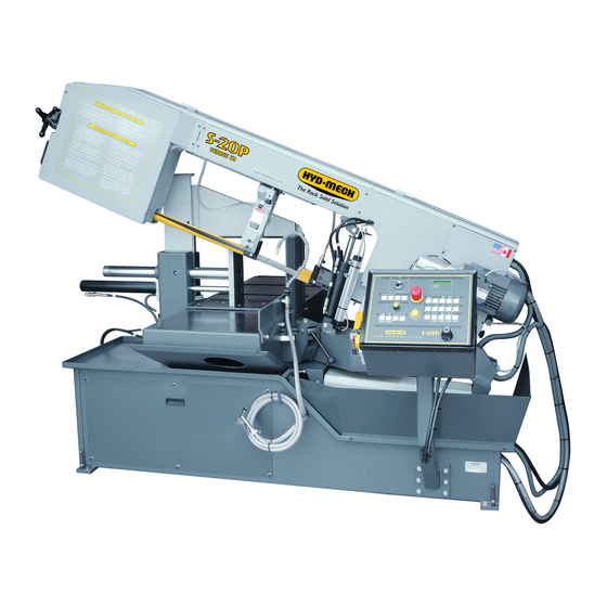
S20P
393396
THANK YOU,
On behalf of everyone at HYD·MECH Group Limited, we would like to thank and congratulate you on your decision to
purchase a HYD·MECH bandsaw.
Your new machine is now ready to play a key role in increasing the efficiency of your operation, helping you to reduce cost
while boosting quality and productivity.
To ensure you are maximizing the power and versatility of your new HYD·MECH bandsaw, please take the time to
familiarize yourself and your employees with the correct operation and maintenance procedures as outlined in this
manual. Please keep this instruction manual for future reference in a known location and easily accessible to all users of
the device.
HYD·MECH offers a great variety of options, components, and features for its various models. Therefore, some of the
equipment described in this manual (various illustrations and drawings) may not be applicable to your particular machine.
The information and specifications provided in this manual were accurate at the time of printing. HYD·MECH reserves the
right to discontinue or change specifications or design at any time without notice and without incurring any obligation.
Thank you.
Hyd·Mech Group Limited
P.O. Box 1659, 1079 Parkinson Road
Woodstock, Ontario, N4S 0A9
Phone : (519) 539-6341
Service : 1-877-237-0914
Sales : 1-877-276-SAWS (7297)
Fax : (519) 539-5126
e-mail : info@hydmech.com
Printed FEB 2016
1
Advertisement
Table of Contents

Related Manuals for Hyd-Mech S20P


Summary of Contents for Hyd-Mech S20P
- Page 1 S20P 393396 THANK YOU, On behalf of everyone at HYD·MECH Group Limited, we would like to thank and congratulate you on your decision to purchase a HYD·MECH bandsaw. Your new machine is now ready to play a key role in increasing the efficiency of your operation, helping you to reduce cost while boosting quality and productivity.
-
Page 3: Table Of Contents
BASIC RULES ..........................0.4 SAFETY HAZARD LABELS ......................0.9 SECTION 1 - INSTALLATION INSTALLATION ..........................1.1 SAFETY PRECAUTIONS .........................1.1 LIFTING THE S20P WITH A FORK LIFT ..................1.2 WRAPPED FOR SHIPPING ......................1.2 FOUNDATION, LEVELLING AND ANCHORING ................1.2 CUTTING FLUID ..........................1.3 HYDRAULIC OIL ..........................1.3 WIRING CONNECTIONS .........................1.3 SECTION 2 –... - Page 4 FOR OPTIONAL ASSEMBLIES SEE PDF ON ATTACHED CD ............7.1 MIST COOLANT SYSTEM .......................7.1 WORK STOP ASSEMBLY ........................7.1 WORK LAMP ASSEMBLY ........................7.1 VARIABLE VISE PRESSURE OPTION ...................7.2 OVERHEAD BUNDLING ........................7.2 SECTION 8 - SPECIFICATIONS S20P BANDSAW SPECIFICATION LIST ..................8.1 S20P LAYOUT ..........................8.2 SECTION 9 - WARRANTY WARRANTY .............................9.1...
-
Page 5: Summary
SECTION 0 - SAFETY INSTRUCTIONS SUMMARY All persons operating this machine must have read and understood all of the following sections of this Manual: Section 0 SAFETY Section 2 OPERATING INSTRUCTIONS However, as a memory aid, the following is a summary of the Safety Section. Put Safety First Mandatory Information –... - Page 6 FOREWORD Put Safety First! This Safety Section contains important information to help you work safely with your machine and describes the dangers inherent in our machines. Some of these dangers are obvious, while others are less evident. It really is important to PUT SAFETY FIRST. Make it a habit to consider the hazards associated with any action BEFORE you do it.
- Page 7 Signatures Everyone involved in operation of this machine must sign below to confirm that: I have read and understood all parts of Section 0 – Safety, and Section 2 – Operating Instructions. Name Date Signature Everyone involved in the installation, inspection, maintenance, and repair of this machine must sign below to confirm that: I have read and understood all parts of this Operation and Maintenance Manual.
-
Page 8: Basic Rules
When all operations and procedures are in compliance with this Manual. Hyd-Mech Group cannot accept any liability for personal injury or property damage due to operator errors or non-compliance with the Safety and Operating Instructions contained in this Manual. - Page 9 Responsibilities of the owner Organization of work This Operation and Maintenance Manual must always be kept near the machine so that it is accessible to all concerned. The general, statutory and other legal regulations on accident prevention and environmental protection must also be observed, in addition to the Manual material.
- Page 10 Responsibilities of the operator and maintenance personnel Safety equipment All machines are delivered with safety equipment that must not be removed or bypassed during operation. The correct functioning of safety equipment on the machine must be checked: • at the start of every shift. •...
- Page 11 Gloves Experience has shown that careless use of gloves around machinery is a major factor in serious hand injuries. Gloves should not be worn when operating or adjusting the machine, except: Wear protective gloves when handling bandsaw blades at blade changes. Gloves may be worn when handling work pieces, only if the machine is in Manual Mode and the bandsaw blade is not running.
- Page 12 On Hyd-Mech machines the Master Disconnect Switch will be of one of three types: • Rotary switch mounted in electrical control cabinet door and inter-locked with door •...
-
Page 13: Safety Hazard Labels
SAFETY HAZARD LABELS The safety hazard labels attached to your machine represent important safety information to help you avoid personal injury or death. All supervisors, operators, and maintenance personnel must locate and understand the safety information associated with each hazard label prior to operating or servicing the machine. The safety hazard labels shown below are located at various positions on the machine to indicate possible safety hazards. - Page 14 LOCATION AND PART NUMBERS OF SAFETY HAZARD LABELS ON S20MP Danger Hazardous voltage inside Item N0. 391938 Warning Danger Pinch Point Moving bandsaw blade will cut Item N0. 392801 Item N0. 391937 0.10...
-
Page 15: Section 1 - Installation
SAFETY PRECAUTIONS The S20P has been designed to give years of reliable service. It is essential that operators be alerted to the safe opera- tion of this saw, and the practices to avoid that could lead to injury. The following safety rules are at the minimum neces- sary for the safe installation, operation, and maintenance of the saw. -
Page 16: Lifting The S20P With A Fork Lift
LIFTING THE S20P WITH A FORK LIFT The S20P is shipped with a shipping pallet attached to the saw. When lifting the pallet with a forklift truck make sure that the load is firmly balanced. Minimum fork length of 72" (1827 mm) is recommended to safely lift the pallet. -
Page 17: Cutting Fluid
CUTTING FLUID The S20P uses a pump and reservoir to circulate the necessary cutting fluid to the blade for maximum blade life. Your saw blade supplier will be able to provide information to the cutting fluid products that are available for your needs. -
Page 18: Section 2 - Operating Instructions
SECTION 2 – OPERATING INSTRUCTIONS OPERATOR CONTROL PANEL The operator control panel provides the operator with all the controls necessary to operate the saw after the cutting angle has been set and the stock has been loaded and secured. All of the electrical functions and Feed Rate setting are operat- ed from the control panel. -
Page 19: Manual Mode Machine Operation
Manual Mode Machine Operation Manual mode allows for a manual operation of the saw. In this mode all functions are activated be selection of the respec- tive function button on the user interface. To enter the manual mode after the main power has been turned off, press the Machine Start button. Follow the instruc- tions on the display, and select the Manual Mode. -
Page 20: Cycle Parameter Display
Cycle Parameter Display The machine is capable of displaying many parameters, not all of which can be shown on the screen at the same time. Pressing the CYCLE PARAMETERS button will toggle the display of the parameters. The following is a list of available parameters and the corresponding abbreviations as they are shown on the display. -
Page 21: Machine Alarms And Emergencies
PARAMETER DESCRIPTION FACTORY SET VALUE LANGUAGE Language which will be displayed on the interface English MACHINE TYPE Machine type S 20 P MAN & SAD CYCLE Manual and semi automatic PEDAL START Pedal start option INVERTER Inverted blade motor drive BLADE SPEED PROXY Machine equipped with blade speed proximity switch Machine equipped with low level lubricant sensor for mist... -
Page 22: Setting The Head Linear Potentiometer (Rhls/Fhls Limit)
HEAD SWING and BREAK An integral function of the S20P is the ability to make mitered cuts at angles between 90 and 30 degrees. The Head swing of the S20P is easily changed to set a different cutting angle by first releasing the Angle Brake lever, and then manually moving the Head to the cutting angle desired. -
Page 23: Coolant Flow
GUIDE ARM POSITIONING The S20P idler side guide arm is adjustable to accommodate varying material widths. The guide arm should be adjusted as close to the material as possible while still allowing it to pass. This process of matching the guide arm spacing to the material size is important to optimize blade life and ensure straightness of the cut. -
Page 24: Blade Basics
Variable pitch (following pages), bi-metal blades (like the ¾ or 4/6 bi-metal blade supplied with the Hyd-Mech machine) last much longer, cut faster and more accurately than the conventional carbon steel blades. In order to take advantage of the superiority of bi-metal blades, it is critical to properly “break in” a new blade. This is accomplished by taking two or three cuts through solid four or five-inch diameter mild steel at an extremely slow feed rate. - Page 25 DETERMINE OPTIMUM BLADE PITCH – TEETH PER INCH (T.P.I.) Selecting a blade with proper tooth pitch is important in order to achieve optimal cutting rates and good blade life. For cutting narrow or thin wall structural materials, a fine blade with many teeth per inch (T.P.I.) is recommended. For wide materials a blade with a coarse pitch should be used.
-
Page 26: Section 3 - Maintenance And Troubleshooting
SECTION 3 – MAINTENANCE AND TROUBLESHOOTING SAFETY DURING MAINTENANCE AND TROUBLESHOOTING “Lock-out”, or “Lock-out Tag-out” are terms that refer to procedures taken to prevent the unexpected start-up, or other re- lease of energy, by a machine, whenever anyone is required to remove or bypass safety guards or devices, or whenever anyone is required to place part of his body in a hazard area. -
Page 27: Blade Changing Procedure
BLADE CHANGING PROCEDURE NOTE: Wear gloves for protection from the sharp blade. 1. Open the Wheels door by unscrewing the two knobs. 2. Loosen the Blade Tensioner by turning counter clockwise. 3. Open the blade guard at idler guide arm by undoing the mounting screws and removing it as illustrated below. - Page 28 4. Remove the worn blade by sliding it off the wheels and out off both guide blocks 5. Your new blade will be in a coil. While wearing gloves, hold the blade away from yourself; twist the blade to uncoil it.
-
Page 29: Blade Tracking Adjustment
9. With the blade in place, turn the tensioner handle clockwise until Bade Tension Display shows required value. Recommended blade tension is between 1250 - 1350 kg. If blade is under tensioned the blade motor will not start. 10. Replace the blade cover and close wheels door. 11. -
Page 30: Blade Guide Adjustment
Drive Wheel Adjustment The Drive Wheel adjustment is closely linked to adjustment of the Idler Wheel. The purpose of the adjustment is to ensure that the back of the blade remains about .040-.080” away from the wheel flange during rotation. 1. -
Page 31: Carbide Replacement
CARBIDE REPLACEMENT The blade guide blocks are equipped with one top carbide and two side carbide inserts each. The working life of carbide guides is practically the same as that of the machine itself. However, if required they can be replaced by removing the plate fixing screw as shown. -
Page 32: Blade Brush Adjustment
4. If the blade touches the square at the bottom loosen the top fixing screw “ A’ ” and tighten screws “ B’ ” the same amount until the square edge contacts the blade uniformly along the whole blade width. If contact is at the top of the square, loosen the bottom fixing screw “A”... -
Page 33: Angle Brake Adjustment
As shown, there are two springs on socket head screws holding the brush assembly against the blade. There is also an adjusting stop socket set screw A with a hex nut C on it. This adjusting set screw works as a stop determining the brush position in respect to the blade. -
Page 34: Blade Tension Slide Adjustment
BLADE TENSION SLIDE ADJUSTMENT To reduce the play, which may develop over time between the blade tensioner slide and slide gibs, adjust the screws be- tween the gibs and slide as follows: 1. Remove the head front cover. 2. Undo blade tension. 3. -
Page 35: Lubrication
The S20P was designed to minimize the maintenance requirements. Moving assemblies and contact faces need lubrica- tion on a regular schedule whether they are in heavy use or not. The lubrication requirements of the S20P are primarily the saw pivot points which are equipped with grease fittings, and metal to metal surfaces that require lubrication to pre- vent wear and seizure. - Page 36 SECTION 4 - ELECTRICAL ELECTRICAL SCHEMATICS: SEE PDF ON ATTACHED CD...
-
Page 37: Section 5 - Hydraulic
SECTION 5 - HYDRAULIC The S20P hydraulic system does not require any special work on a new machine before its start up. The hydraulic tank is filled with Texaco Rando HD46 hydraulic oil and all machine functions have been tested at the factory to ensure proper operation upon initial start up. -
Page 38: Section 6 - Mechanical Assemblies
SECTION 6 - MECHANICAL ASSEMBLIES MECHANICAL ASSEMBLY DRAWINGS & PARTS LIST: SEE PDF ON ATTACHED CD... -
Page 39: Section 7 - Optional Equipment
SECTION 7 - OPTIONAL EQUIPMENT FOR OPTIONAL ASSEMBLIES SEE PDF ON ATTACHED CD MIST COOLANT SYSTEM Mist Coolant – the air powered pump delivers a regulated number of pulses of lubri- cant to a single applicator nozzle. The unit has two control screws. Pulse / Minute –... -
Page 40: Variable Vise Pressure Option
VARIABLE VISE PRESSURE OPTION Vise clamping pressure adjustment is located on the idler side of the machine base. Clamping pressure is indicated by the pressure gauge above the pressure control knob. Turning the knob clockwise increases clamping pressure. The clamp- ing pressure can be changed infinitely form 50PSI to 600PSI (full pump pressure). -
Page 41: Section 8 - Specifications
SECTION 8 - SPECIFICATIONS S20P Bandsaw Specification List S-20P BANDSAW SPECIFICATIONS 13” (355mm) high x 18” (457mm) wide rectangular Capacity - 90º 13” (330mm) dia round 13” (355mm) high x 10.9” (277mm) wide rectangular Capacity - 45º 12” (305mm) dia round 13”... -
Page 42: S20P Layout
S20P LAYOUT... -
Page 43: Section 9 - Warranty
MOTOR, GEARBOX, PUMP, ELECTRIC COMPONENTS, VALVES, HOSES, FITTINGS, and any other items used in the manufacture of the S20P, but not originally manufactured by Hyd·Mech are subject to the original manufacturer’s warranty. Hyd·Mech will provide such assistance and information as is necessary and available to facilitate the user’s claim to such other manufacturer.
Need help?
Do you have a question about the S20P and is the answer not in the manual?
Questions and answers
BLADE COLANT PUMP NOT TURNING ON PULLED MOTOR OUT NO POWER FEEDING PUMP
The Hyd-Mech S20P uses a pump and reservoir to circulate cutting fluid to the blade. If the blade coolant pump is not turning on, possible reasons include:
1. No Coolant Supplied – The machine does not come with coolant, so it must be added before operation.
2. Incorrect Coolant Mixture – Ensure the coolant is mixed correctly:
- Oil-based: 1:10 ratio (one part coolant to 10 parts water).
- Synthetic: As recommended by the manufacturer.
3. Electrical Connection Issues – Check for shipping damage to electrical conduits, cords, or hydraulic hoses.
4. Power Hook-Up – Ensure the machine is properly connected to the correct three-phase AC voltage.
5. Control System Issue – The pump may not activate if the machine is not set in the correct operational mode.
Verifying these factors should help identify and resolve the issue.
This answer is automatically generated