Table of Contents
Advertisement
Quick Links
Advertisement
Table of Contents

Related Manuals for TYAN GT62B-B5539


Summary of Contents for TYAN GT62B-B5539
- Page 1 GT62B-B5539 Service Engineer’s Manual http://www.tyan.com...
- Page 2 http://www.tyan.com...
- Page 3 TECHNOLOGY CORPORATION and has been reviewed for accuracy and reliability prior to printing. MiTAC assumes no liability whatsoever, and disclaims any express ® or implied warranty, relating to sale and/or use of TYAN products including liability or warranties relating to fitness for a particular purpose or merchantability. MiTAC retains the right to make changes to produce descriptions and/or specifications at any time, without notice.
-
Page 4: Fcc Declaration
This Class A digital apparatus complies with Canadian ICES-003. Cet appareil numérique de la Classe A est conforme à la norme NMB-003 du Canada. Notice for Europe (CE Mark) ● This product is in conformity with the Council Directive 2014/30/EU. http://www.tyan.com... - Page 5 Replace only with the same or equivalent type recommended by manufacturer. Dispose of used battery according to manufacturer instructions and in accordance with your local regulations. VCCI-A ● この装置は、クラスA情報技術装置です。この装置を家庭環境で使用すると電波妨 害を引き起こすことがあります。この場合には使用者が適切な対策を講ずるよう要 求されることがあります。 Safety: EN/IEC 60950-1 ● This equipment is compliant with CB/LVD of Safety: EN/IEC 60950-1. http://www.tyan.com...
-
Page 6: About This Manual
How this guide is organized This guide contains the following parts: Chapter 1: Overview This chapter provides an introduction to the TYAN GT62B-B5539 barebones and standard parts list, describes the external components, gives an overview of the product from different angles. -
Page 7: Safety And Compliance Information
Safety and Compliance Information Before installing and using TYAN GT62B-B5539, take note of the following precautions: ·Read all instructions carefully. ·Do not place the unit on an unstable surface, cart, or stand. ·Do not block the slots and opening on the unit, which are provided for ventilation. -
Page 8: Safety Information
You must become familiar with the safety information in this guide before you install, operate, or service TYAN products. Symbols on Equipment Caution. This symbol indicates a potential hazard. - Page 9 · Make sure the rack is level and stable before installing an appliance in the rack. · Make sure the leveling jacks are extended to the floor. · Make sure the full weight of the rack rests on the leveling jacks. http://www.tyan.com...
- Page 10 If you do not ground the Green/Yellow tab, it can cause an electrical shock due to high leakage currents. · Do not place objects on AC power cords or cables. Arrange them so that no one might accidentally step on or trip over them. http://www.tyan.com...
- Page 11 TYAN, your authorized TYAN partner, or their agents. Equipment Modifications · Do not make mechanical modifications to the system. TYAN is not responsible for the regulatory compliance of TYAN equipment that has been modified.
- Page 12 – Liquid has been spilled on the product or an object has fallen into the product. – The product has been exposed to rain or water. – The product has been dropped or damaged. – The product does not operate normally when you follow the operating instructions. http://www.tyan.com...
- Page 13 http://www.tyan.com...
-
Page 14: Table Of Contents
Table of Contents Chapter 1: Overview............... 17 About the TYAN GT62B-B5539 ..........17 Product SKUs ................. 17 Features .................. 18 Standard Parts List ..............27 1.4.1 Box Contents and Accessories........27 About the Product ..............28 ... - Page 15 Power Distribution Board Pin Definitions ......67 Replacing the Power Supply ..........69 Appendix I: Cable Connection Tables .......... 73 Appendix II: Fan and Temp Sensors ..........75 Appendix: FRU Parts Table ............77 Appendix IV: Technical Support ........... 79 http://www.tyan.com...
- Page 16 NOTE http://www.tyan.com...
-
Page 17: Chapter 1: Overview
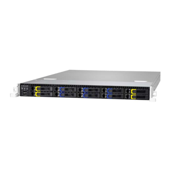
2.5” NVMe SSD hard drives. The GT62B-B5539 uses TYAN’s latest chassis featuring a robust structure and a solid mechanical enclosure. All of this provides GT62B-B5539 the power and flexibility to meet the needs of nowadays server application. Product SKUs... -
Page 18: Features
Features TYAN GT62B-B5539 (B5539G62BV6E4HR-D41-2T (BTO)) Form Factor 1U Rackmount Gross Weight 16 kg Chassis Model GT62B System Dimension (D x W x 24.6" x 17.2" x 1.72" (625.4 x 436 x 43.6mm) Motherboard S5539GM4NR-D41-2T Board Dimension Micro ATX, 9.6"x9.6" (243.8x243.8mm) - Page 19 Regulation VCCI Class A CB/LVD Class A Operating Temp. 10° C ~ 35° C (50° F~ 95° F) Operating Non-operating Temp. - 40° C ~ 70° C (-40° F ~ 158° F) Environment In/Non-operating 90%, non-condensing at 35° C http://www.tyan.com...
- Page 20 Barebone (1) GT62B-B5539 Barebone Package Manual (1) Quick Installation Guide Contains Installation CD (1) TYAN installation CD TYAN GT62B-B5539 (B5539G62BV6E4HR-D41 (BTO)) Form Factor 1U Rackmount Gross Weight 16 kg Chassis Model GT62B System Dimension (D x W x H) 24.6" x 17.2" x 1.72" (625.4 x 436 x 43.6mm)
- Page 21 LAN / PXE boot support / ACPI 3.0/ACPI sleeping states S4,S5 Operating System OS supported list Please refer to our Intel OS supported list. FCC (DoC) Class A CE (DoC) Class A Regulation VCCI Class A CB/LVD Class A http://www.tyan.com...
- Page 22 RoHS 6/6 Compliant Barebone (1) GT62B-B5539 Barebone Package Contains Manual (1) Quick Installation Guide Installation CD (1) TYAN installation CD TYAN GT62B-B5539 (B5539G62BV6E4H-D41-2T (BTO)) Form Factor 1U Rackmount Gross Weight 16 kg Chassis Model GT62B System Dimension (D x W x 24.6"...
- Page 23 Pre-install TYAN M2091, PCI-E x16 1U riser card Riser Card M5539-2E MEZZ card, (2) mini-SAS HD Pre-install TYAN connectors, PCI-E Gen3 x8 link; MEZZ Card M2092 half height NVMe MEZZ card, (2) mini-SAS HD connectors, PCI-e Gen3 x8 link (2) 10GbE ports, (2) GbE ports, (1) PHY dedicated...
- Page 24 Barebone (1) GT62B-B5539 Barebone Package Manual (1) Quick Installation Guide Contains Installation CD (1) TYAN installation CD TYAN GT62B-B5539 (B5539G62BV6E4H-D41 (BTO)) Form Factor 1U Rackmount Gross Weight 16 kg Chassis Model GT62B System Dimension (D x W x H) 24.6" x 17.2" x 1.72" (625.4 x 436 x 43.6mm)
- Page 25 Up to 64GB/128GB UDIMM/RDIMM Memory channel 2 Channels Memory voltage 1.2V PCI-E (1) PCI-E Gen3 x8 slot Pre-install TYAN M2091, PCI-E x16 1U riser card Riser Card Expansion Slots M5539-2E MEZZ card, (2) mini-SAS HD Pre-install TYAN connectors, PCI-E Gen3 x8 link;...
- Page 26 Non-operating Temp. - 40° C ~ 70° C (-40° F ~ 158° F) Environment In/Non-operating 90%, non-condensing at 35° C Humidity RoHS RoHS 6/6 Compliant Barebone (1) GT62B-B5539 Barebone Package Contains Manual (1) Quick Installation Guide Installation CD (1) TYAN installation CD http://www.tyan.com...
-
Page 27: Standard Parts List
Standard Parts List This section describes GT62B-B5539 package contents and accessories. Open the box carefully and ensure that all components are present and undamaged. The product should arrive packaged as illustrated below. 1.4.1 Box Contents and Accessories If any items are missing or appear damaged, contact your retailer or browse to TYAN’s website for service:... -
Page 28: About The Product
Power/ID LED LAN2 LED LAN1 LED Warning (IPMI) LED HDD LED Power Button ID Button Reset Button USB Ports NOTE: HDD form factor and capacity size support: (6) 2.5” Enterprise 15mm SATA & SAS HDD & (4) 2.5” NVMe SSD. http://www.tyan.com... -
Page 29: Led Definitions
Power up and power down the system(Use a pin) Press once the ID (UID) on the Front Panel, the blue ID ID(UID) LED on the rear panel will light up. The Power LED on the front panel will turn blue. Reset Press to reset the system. http://www.tyan.com... -
Page 30: System Rear View
Power Supply ID LED Button LAN5 Port (dedicated for IPMI) USB3.0 Ports VGA Port Serial Port (COM1) LAN4 (Intel i210) LAN3 (Intel i210) LAN2 (Intel X557, optional) LAN1 (Intel X557, optional) ID LED (blue) Expansion Slot (support full-height card) http://www.tyan.com... - Page 31 Redundant Power SKU 1+1 RPSU ID LED Button LAN5 Port (dedicated for IPMI) USB3.0 Ports VGA Port Serial Port (COM1) LAN4 (i210) LAN3 (i210) LAN2 (X557, optional) LAN1 (X557, optional) ID LED (blue) Expansion Slot (support full-height card) http://www.tyan.com...
-
Page 32: System Top View
1.5.4 System Top View Single Power SKU HDD Trays M1706G62-FPB and Front Panel Tray M1274G62B-BP12E-10 HDD Backplane Board System Fans Power Supply Heatsink M5539-2E MEZZ Card M2091 Riser Card M2092 MEZZ Card http://www.tyan.com... - Page 33 Redundant Power SKU HDD Trays M1706G62-FPB and Front Panel Tray M1274G62B-BP12E-10 HDD Backplane Board System Fans M7016-B7066 Power Distribution Board 1+1 RPSU Heatsink M5539-2E MEZZ Card M2091 Riser Card M2092 MEZZ Card http://www.tyan.com...
-
Page 34: Motherboard (S5539) Layout
The board you receive may not look exactly like the above diagram. The DIMM slot numbers shown above can be used as a reference when reviewing the DIMM population guidelines shown later in the manual. For the latest board revision, please visit our web site at http://www.tyan.com. http://www.tyan.com... -
Page 35: Motherboard Components
7-pin Vertical SATA3.0 Connector (SATA3) Port #2 (LAN2) (J2) COM2 Header (COM2) 7-pin Vertical SATA3.0 Connector (SATA2) TYAN Module Header (J11) 7-pin Vertical SATA3.0 Connector (SATA1) FAN Header for BB FAN Board (J4) 7-pin Vertical SATA6.0 Connector (SATA0) 4-pin Fan Connector (J19) - Page 36 LAN1 LED Header (2PHD_2) RTC Clear CMOS set (3PHD_1) Slots PCI-e Slot#1 (Gen3 x8 link, open-end OCP slot for TYAN LAN/SAS card (OCP1) (J8) type)(J6) PCI-e Slot#2 (Gen2 x4 link, open-end OCP slot for TYAN LAN/SAS card (OCP2) (J15) type)(J5)
-
Page 37: Led Definitions
The LED shuts off when no M.2 devices or M.2 devices no active. The LED blinks per second to Green indicate that M.2 devices is active and working normally. Signal VCC3AUX LED1 ID LED State Description System not identified Blue System identified http://www.tyan.com... - Page 38 NOTE http://www.tyan.com...
-
Page 39: Chapter 2: Setting Up
Caution! To avoid damaging the motherboard and associated components, do not use torque force greater than 7kgf/cm (6.09 lb/in) on each mounting screw for motherboard installation. Do not apply power to the board if it has been damaged. http://www.tyan.com... -
Page 40: Precautions
Working on a system that is connected to a power supply can be extremely dangerous. Follow the guidelines below to avoid damage to GT62B-B5539 or injury to yourself. Ground yourself properly before removing the top cover of the system. -
Page 41: Installing Motherboard Components
HDD and add-on cards. 2.1.1 Removing the Chassis Cover Follow these instructions to remove the GT62B-B5539 chassis cover. Loosen the screw on the left side and the thumb screw on the back side. Slide the top cover out. -
Page 42: Installing The Memory
Align the memory module with the slot. When inserted properly, the memory slot locking levers lock automatically onto the indentations at the ends of the module. Follow the recommended memory population table to install the other memory modules. http://www.tyan.com... -
Page 43: Installing Hard Drives
2.1.3 Installing Hard Drives Follow these instructions to install a hard drive. Pull the locking lever open. Slide the HDD tray out. Unscrew the HDD tray bracket. http://www.tyan.com... - Page 44 Place a hard drive into the drive tray and use 4 screws to secure the HDD. Reinsert the HDD tray into the chassis and push the locking lever back to secure the tray. http://www.tyan.com...
-
Page 45: Rack Mounting
Screws Kit x 1 Mounting Brackets x 4 Installing the Server in a Rack Follow these instructions to mount the TYAN GT62B-B5539 into an industry standard 19" rack. NOTE: Before mounting the TYAN GT62B-B5539 in a rack, ensure that all internal components have been installed and that the unit has been fully tested. -
Page 46: Installing The Inner Rails To The Chassis
2.2.1 Installing the inner Rails to the Chassis Screw the mounting ear to each side of TYAN GT62B-B5539 as shown using two screws of #6-32 L5.3(D) from the supplied screws kit. Draw out the inner rails from rail assembly. Install inner rails to left and right sides of chassis using 1 M4-4L(A) screw for each side. -
Page 47: Installing The Outer Rails To The Rack
Rear Bra cket x 2 Front Brack et x2 Secure the front bracket to outer rail with 2 M4-4L(A) screws. Reserve the distance same as in Step 2 on rear bracket. Secure the rear bracket to outer rail with 2 M4-4L(B) screws. http://www.tyan.com... - Page 48 Secure the outer rail to the rack using 2 brackets and 4 M5-20L(C) screws for each side. Secure the mounting brackets from inside, not outside, of the rack. Mounting Bra cket http://www.tyan.com...
-
Page 49: Rack Mounting The Server
Draw out the middle rail to the latch position. Lift the chassis and then insert the inner slide rails into the middle rails. Push the chassis in and press the latch key (A). Then push the whole system into the rack (B). http://www.tyan.com... - Page 50 Secure the mounting ears of chassis to the rack with 2 M5-15L(C) screws. NOTE: To avoid injury, it is strongly recommended that two people lift the TYAN GT62B-B5539 into the place while a third person screws it to the rack. http://www.tyan.com...
-
Page 51: Chapter 3: Replacing Pre-Installed Components
This chapter explains how to replace the pre-installed components, including the M1706G62-FPB Front Panel Board, M1274G62B-BP12E-10 SATA/SAS HDD Backplane Board, PCI-E Card, System Fan and Power Supply Unit etc. 3.0.2 Disassembly Flowchart The following flowchart outlines the disassembly procedures. http://www.tyan.com... -
Page 52: Removing The Cover
Removing the Cover Before replacing any parts you must remove the chassis cover. Follow Section 2.1.1 Removing the Chassis Cover(page 41) to remove the cover of the GT62B-B5539. Replacing the M2091 and M2092 Cards Follow these instructions to replace the M2092 M2091 cards. - Page 53 M2091 Riser Card Unscrew to lift up the riser card bracket. Unscrew the M2091 riser card to replace with a new one. Follow the steps described earlier in reverse to reinstall the riser card bracket. http://www.tyan.com...
-
Page 54: Replacing The M5539-2E Mezz Card
Replacing the M5539-2E MEZZ Card Follow these instructions to replace the M5539-2E MEZZ card. Disconnect the cables. Unscrew the M5539-2E MEZZ card to replace with a new one. Follow the steps described earlier in reverse to reinstall a new M5539-2E MEZZ card. http://www.tyan.com... -
Page 55: Replacing The Front Panel Board
Replacing the Front Panel Board Follow these instructions to replace the M1706G62-FPB Front Panel Board. Release cables from the cable clip. Unscrew the front panel tray. Pull the front panel tray from the chassis. Disconnect cables from the front panel board. http://www.tyan.com... - Page 56 Unscrew the Front Panel Board to replace a new one. Follow the steps described earlier in reverse to reinstall the USB Board. Repeat the procedures described earlier in reverse order to place the front panel tray back into place. http://www.tyan.com...
-
Page 57: Front Panel Board Features
Pin Net Name Function Pin Net Name Function VCC_USB0 Power connect to 5V (for USB) 6 USB_P1_P USB_P1 + VCC_USB1 Power connect to 5V (for USB) 7 Ground USB_P0_N USB_P0 - Ground USB_P1_N USB_P1 - USB_P0_P USB_P0 + 10 NC http://www.tyan.com... -
Page 58: Replacing The System Fan
Replacing the System Fan Follow these instructions to replace the system fan. Disconnect the fan power cord from the HDD backplane board. Take out the failed fan. Pull the front rubber screws out. http://www.tyan.com... - Page 59 Pull the rear rubber screws out. After replacing the new fan, follow the steps described earlier in reverse order to reinstall the fan into the chassis. http://www.tyan.com...
-
Page 60: Replacing The Hdd Backplane Board
Follow these instructions to replace the M1274G62B-BP12E-10 HDD Backplane Board. Disconnect all cables attached to the HDD BP Board. Unscrew to lift the HDD Backplane bracket up. Loosen 8 screws to lift up the mylar and replace with a new HDD BP Board. http://www.tyan.com... -
Page 61: Hdd Backplane Board Specifications
(2+1) 4Pin power connector connect to MB (2) 2x5 pin JTAG connector (TBD) (1) 2x5 pin SGPIO connector connect to MB (10) Green LEDS for HDD activity LEDs (10) Red LEDS for HDD fault http://www.tyan.com... - Page 62 J29: Front Panel Connector Signal Signal TACH1 TACH6 TACH2 TACH7 TACH3 TACH8 TACH4 TACH9 TACH5 TACH10 TACH11 TACH12 FAN1/2/3/4/5/6: 8-pin Fan Header Signal Signal PWM1 VCC1 TACK1 GND1 GND2 TACK2 VCC2 PWM2 http://www.tyan.com...
-
Page 63: Hdd Bp Board Led Definitions
Access Activity Blinking HDD Fail Solid On Don’t care NOTE: Some RAID cards have compatibility issue, therefore, when the HDD is under the HDD Fail, Identify or Rebuild state, simply ignore the Activity LED and focus on the Status LED. http://www.tyan.com... -
Page 64: Removing The Motherboard
Release the expansion slot locking tab and unscrew the riser card bracket. Lift up the riser card bracket and disconnect all cables. Remove the nine screws securing the motherboard to the chassis. Carefully lift the motherboard from the chassis. http://www.tyan.com... -
Page 65: Replacing The Power Distribution Board (Optional)
Step 3. Push the power distribution board backward to lift it up from the chassis. After replacing a new power distribution board, follow the procedures in reverse order to reinstall the power distribution board back into the chassis. http://www.tyan.com... -
Page 66: M7016-B7066-Pdb Power Distribution Board Feature
36.7 x 420.40 x 2mm, 6-layer PCB (1) ATX 24pin Power Connector (2) 2x4pin Power Connector (2) Power input Connector Integrated I/O (2) 1x4pin Power Connector (1) 2x2pin Power Connector (1) PSMI Connector http://www.tyan.com... -
Page 67: Power Distribution Board Pin Definitions
+12V1 +12V1 +12V3a +12V3a PW1: 24-pin Power Connector Definition Definition 3.3V 3.3V Power Good 5VSB +12V +12V 3.3V 3.3V +12V PS_ON Reset PW2/PW3: 4-pin Power Connector Definition +12V PW4: 4-pin Power Connector Definition Definition +12V +12V J4: PSMI Connector http://www.tyan.com... - Page 68 Definition SMBUS_CLK SMBUS_DATA http://www.tyan.com...
-
Page 69: Replacing The Power Supply
Single Power SKU Disconnect the 4-pin power cables from the M1277 HDD Backplane. Disconnect the 24-pin main power and PSMI cable from the Motherboard. Remove seven (7) screws that secure the power supply unit to the chassis. http://www.tyan.com... - Page 70 Slide out the whole power supply unit. Unscrew to remove the iron pieces from the power supply. Install a new power supply unit following the steps in reverse. http://www.tyan.com...
- Page 71 Redundant Power SKU Press and hold the latch to pull the power supply out. After replacing a new power supply, press and hold the latch to push the power supply unit back into the chassis. http://www.tyan.com...
- Page 72 NOTE http://www.tyan.com...
-
Page 73: Appendix I: Cable Connection Tables
SATA0/SATA1 → SATA0_3 Mini-SAS Cable /SGPIO1 SATA2/SATA3 → SATA4_7 Mini-SAS Cable /SATA4/SATA5 → Fan Ctrl cable M1274 Backplane (BP) Board to M5539-2E Cable M1274 Connect to M5539-2E Mini-SAS HD → NVME0 NVME0 Cable Mini-SAS HD → NVME1 NVME1 Cable http://www.tyan.com... - Page 74 B4P P5 5. Power Cables (For Redundant SKU) M7016-PDB to S5539 MB M7016 Connect to S5539 → 2x12P CABLE PWR1 → PSMI CABLE M7016-PDB to M1274 Backplane (BP) Board M7016 Connect to M1274 → B4P CABLE → B4P CABLE http://www.tyan.com...
-
Page 75: Appendix Ii: Fan And Temp Sensors
(rpm) Temp Sensor: SYS_Air_Inlet (J23) & M/B_Air_Inlet (U66). They detect the system temperature around. NOTE: The system temperature is measured in a scale defined by Intel, not in Fahrenheit or Celsius. http://www.tyan.com... - Page 76 CPU0_DIMM_B0 Temperature of CPU0 DIMM B0 Slot CPU0_DIMM_B1 Temperature of CPU0 DIMM B1 Slot BIOS FAN Sensor Name Explanation SYS_FAN_1 Fan speed of SYS_FAN_1 SYS_FAN_2 Fan speed of SYS_FAN_2 SYS_FAN_3 Fan speed of SYS_FAN_3 SYS_FAN_4 Fan speed of SYS_FAN_4 http://www.tyan.com...
-
Page 77: Appendix: Fru Parts Table
Appendix: FRU Parts Table GT62B-B5539 FRU Parts Item Model Number Part Number Picture Description TF-POWER CORD;SBU,US,125 V,16 FRU-CS-0330 332810000514 AWG(1.31mm²),1800mm,AC PWR CORD Cable TF-PWR CCBL-0300 332810000281 CORD;EU,250V,H05VV-FX3C,10A,0.75MM TF-POWER SUPPLY;SBU,500 W,DELTA,DPS-500AB-5 C,(00F),1U FRU-PS-0072 471100000243 MODULE,REV.00F (For Single PSU SKU) Power Supply TF-POWER SUPPLY;... - Page 78 NOTE http://www.tyan.com...
-
Page 79: Appendix Iv: Technical Support
MiTAC serves multiple market segments with the industry’s most competitive services to support them. Please feel free to contact us directly for this service at tech-support@tyan.com Help Resources: 1. See the beep codes section of this manual. - Page 80 (RMA) number. The RMA number should be prominently displayed on the outside of the shipping carton and the package should be mailed prepaid. TYAN will pay to have the board shipped back to you. TYAN® GT62B-B5539 Service Engineer’s Manual V1.0c Document No.: D2355-100 http://www.tyan.com...
Need help?
Do you have a question about the GT62B-B5539 and is the answer not in the manual?
Questions and answers