Table of Contents
Advertisement
Quick Links
Advertisement
Table of Contents

Related Manuals for TYAN GT24-B7016-LE


Summary of Contents for TYAN GT24-B7016-LE
- Page 1 GT24-B7016-LE Service Engineer’s Manual http://www.tyan.com...
- Page 2 http://www.tyan.com...
- Page 3 Corporation and has been reviewed for accuracy and reliability prior to printing. MiTAC assumes no liability whatsoever, and disclaims any ® express or implied warranty, relating to sale and/or use of TYAN products including liability or warranties relating to fitness for a particular purpose or merchantability.
- Page 4 There will be danger of explosion if battery is incorrectly replaced. Replace only with the same or equivalent type recommended by manufacturer. Dispose of used battery according to manufacturer instructions and in accordance with your local regulation`ns. http://www.tyan.com...
-
Page 5: About This Manual
About this Manual This manual provides you with instructions on installing your TYAN GT24-B7016-LE. This Manual is intended for experienced users and integrators with hardware knowledge of personal computers. This manual consists of the following parts: Chapter1: Provides an introduction to the TYAN... -
Page 6: Safety Information
SAFETY INFORMATION Before installing and using TYAN GT24-B7016-LE, take note of the following precautions: ·Read all instructions carefully. ·Do not place the unit on an unstable surface, cart, or stand. ·Do not block the slots and opening on the unit, which are provided for ventilation. -
Page 7: Table Of Contents
Table of Contents Chapter 1: Overview ................. 9 About the TYAN GT24-B7016-LE ..........9 Product Models................. 9 Features.................. 10 Standard Parts List ..............14 1.4.1 Box Contents ..............14 1.4.2 Accessories ..............15 Optional Parts ................. 16 About the Product ..............17 1.6.1... - Page 8 M1232 HDD Board Features ........... 61 3.8.2 M1232 HDD Board Connector Pin Definitions ....63 Replacing the Power Distribution Board ....... 65 3.10 Replacing the Power Supply..........66 Appendix I: Cable Connection Tables .......... 67 Appendix II: Technical Support............. 69 http://www.tyan.com...
-
Page 9: Chapter 1: Overview
Intel GT24-B7016-LE server system is capable of offering scalable 32 and 64-bit computing, high bandwidth memory design, and lightning-fast PCI-E bus implementtation.GT24-B7016-LE not only empowers your company in nowadays IT demand but also offers a smooth path for future application usage. -
Page 10: Features
Features TYAN GT24-B7016-LE (B7016G24W4HR-LE/B7016G24V4HR-LE) Form Factor 1U Rackmount Chassis Name GT24 System Dimension (D x W x H) 25.4" x 17.2" x 1.72" (645 x 436 x 43.6mm) Motherboard S7016-LEWGM3NR-LE/S7016-LEGM3NR-LE Gross Weight 16 kg Buttons (1) RST / (1) NMI / (1) ID / (1) PWR w/ LED... - Page 11 Memory voltage 1.5V PCI-E (1) PCI-E Gen.2 x8 slot / (1) PCI-E Gen.2 x16 slot (w/ x8 link) Expansion Pre-install TYAN Riser M2083-RS, PCI-E x16 1U riser card (left) / M2081-2, PCI-E x8 Slots Card 1U riser card (right) Port Q'ty...
- Page 12 Humidity RoHS RoHS 6/6 Complaint Barebone (1) GT24B7016-LE Barebone Package Installation CD (1) TYAN installation CD Contains Heatsink / Cooler (2) CHSK-0380, LGA1366 CPU heatsinks for S7016-LE Rail kit (1) CRAL-0031, sliding rail kit for KGT24 Mounting Ear (1) CEAR-0050, mounting ear kit for GT20/ GT24...
- Page 13 Others (1) HDD screw pack Power Cord (2) CCBL-0316, CCC/China http://www.tyan.com...
-
Page 14: Standard Parts List
Standard Parts List This section describes GT24-B7016-LE package contents and accessories. Open the box carefully and ensure that all components are present and undamaged. The product should arrive packaged as illustrated below. 1.4.1 Box Contents Component Description 1U chassis,(4) hot swap HDDbays ®... -
Page 15: Accessories
If any items are missing or appear damaged, contact your retailer or ® browse to TYAN ’s website for service: http://www.tyan.com ® The web site also provides information of other TYAN products, as well as FAQs, compatibility lists, BIOS settings, etc. ® 1 x TYAN 2 x Heatsinks... -
Page 16: Optional Parts
Rail Kit Rail with Bracket x 2 Screw Pack Optional Parts Model Item Picture Quantity Description Number Chassis Front Bezel for GT series 1U CFBZ-0070 Front-Bezel chassis http://www.tyan.com... -
Page 17: About The Product
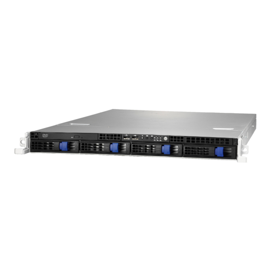
The following views show you the product. 1.6.1 System Front View Control board Slim SATA DVD-RW drive Hot-swap HDD Bays ID LED Warning LED BMC LED USB ports ID button Reset button Power button(with LED) NIC3 NIC2 NMI button NIC1 1.6.2 System Rear View http://www.tyan.com... -
Page 18: Led Definitions
Description Green 10Mb/100Mb/1000Mb linked RJ-45 Linkage/ Blinking Green 10Mb/100Mb/1000Mb activity Activity(left) No LAN linked Amber 1000Mb linked/activity RJ-45 Linkage/ Green 100Mb linked/activity Activity(Right) 10Mb mode or No LAN linked NOTE: “Left” and “Right” are viewed from the rear panel. http://www.tyan.com... - Page 19 10Mb/100Mb/1000Mb linked RJ-45 Linkage/ Blinking Green 10Mb/100Mb/1000Mb activity Activity(left) No LAN linked Amber 1000Mb linked/activity RJ-45 Linkage/ Green 100Mb linked/activity Activity(Right) 10Mb mode or No LAN linked ID LED State Color Description Blue System identified ID LED System not identified http://www.tyan.com...
-
Page 20: Motherboard (S7016-Le) Layout
1.6.4 Motherboard (S7016-LE) Layout The diagram is representative of the latest board revision available at the time of publishing. The board you receive may not look exactly like the above diagram. http://www.tyan.com... -
Page 21: Jumpers & Connectors
BMC Enable/Disable Jumper BMC Update Jumper Flash Manageability Engine (ME) Jumper Clear CMOS Jumper JP2/JP3 COM2 Switch Jumper BMC Flash Jumper PCI-E x8/x16 select Jumper Jumper Legend OPEN - Jumper OFF Without jumper cover CLOSED - Jumper ON With jumper cover http://www.tyan.com... -
Page 22: System Block Diagram
1.6.6 System Block Diagram http://www.tyan.com... -
Page 23: Internal View
1.6.7 Internal View HDD Cage M1232 HDD Backplane Board System Fan Unit Power Supply Memory Slots CPU Sockets PCI-E Riser Card Assembly Power Distribution Board http://www.tyan.com... - Page 24 NOTE http://www.tyan.com...
-
Page 25: Chapter 2: Setting Up
A grounding strap or an anti-static pad Most of the electrical and mechanical connections can be disconnected with your hands. It is recommended that you do not use pliers to remove connectors as it may damage the soft metal or plastic parts of the connectors. http://www.tyan.com... -
Page 26: Precautions
Working on a system that is connected to a power supply can be extremely dangerous. Follow the guidelines below to avoid damage to GT24-B7016-LE or injury to yourself. Ground yourself properly before removing the top cover of the system. -
Page 27: Installing Motherboard Components
-rd, including CPUs, memory modules and add on cards. 2.1.1 Removing the Chassis Cover Follow these instructions to remove GT24-B7016-LE chassis cover. Unscrew the rear top cover on the back side as shown in the small diagram. Slide the rear top cover out. -
Page 28: Installing The Cpu And Heatsink
2.1.2 Installing the CPU and Heatsink Follow the steps below on installing CPUs and CPU heatsinks. 1. Locate the CPU socket. 2. Press the lever and unlock the CPU socket. http://www.tyan.com... - Page 29 3. Lift the CPU protection cap up and lay the CPU into the socket(A), ensuring pin1 is correctly located(B); 4. Close the socket cover and press the CPU lever down to secure the CPU; http://www.tyan.com...
- Page 30 5. Place the heatsink on top of the CPU and secure it with 8 screws. Note: The system supports two CPUs. For CPU sequence please refer to Chapter 1.6.4. http://www.tyan.com...
-
Page 31: Installing The Memory
Press the memory slot locking levers in the direction of the arrows as shown in the following illustration. Align the memory module with the slot. When inserted properly, the memory slot locking levers lock automatically onto the indentations at the ends of the module. http://www.tyan.com... - Page 32 “2.3 - Board Parts, Jumpers and Connectors” for memory installation. 2). Refer to the memory population option table for recommended memory installation instruction. Memory Population Option Table The following pictures show common types of DDR3 memory modules. http://www.tyan.com...
- Page 33 DIMM D0, D1 & D2 Channel A DIMM A0, A1 & A2 Channel E DIMM E0, E1 & E2 Channel B DIMM B0, B1 & B2 Channel F DIMM F0, F1 & F2 Channel C DIMM C0, C1 & C2 http://www.tyan.com...
- Page 34 The following table outlines the suggested rules for populating memory. For 3 slots per channel RDIMM DIMM2 DIMM1 DIMM0 Single Rank Dual Rank Quad Rank UDIMM DIMM2 DIMM1 DIMM0 Single Rank Dual Rank DIMM with heat spreader DIMM2 DIMM1 DIMM0 http://www.tyan.com...
- Page 35 1). “X” indicates a populated DIMM slot. 2). If installing only one processor, you can choose either CPU0 or CPU1. 3). For two slots per channel configuration, it requires population to start with the DIMM slots furthest away from the processor. http://www.tyan.com...
-
Page 36: Installing Hard Drives
2.1.4 Installing Hard Drives The GT24-B7016-LE supports four 3.5” hard drives. Follow these instructions to install a hard drive. Press the locking lever latch and pull the locking lever open. Slide the HDD tray out. Remove the 6 screws. Place a hard drive into the drive tray. - Page 37 Use 6 HDD screws to secure the HDD. 6. Reinsert the HDD tray into the chassis and press the locking lever to secure the tray. http://www.tyan.com...
-
Page 38: Installing The Pci-E Cards
2.1.5 Installing the PCI-E Cards The GT24-B7016-LE supports one PCI-E expansion slot. Follow these instructions to install the PCI-E card. Pull open the tab of PCI-E slot on the rear panel in the direction as shown to release the PCI bracket. -
Page 39: Rack Mounting
Installing the Server in a Rack Follow these instructions to mount the TYAN GT24-B7016-LE into an industry standard 19" rack. NOTE: Before mounting the TYAN GT24-B7016-LE in a rack, ensure that all internal components have been installed and that the unit has been fully tested. -
Page 40: Installing The Inner Rails To The Chassis
2.2.2 Installing the inner Rails to the Chassis Screw the mounting ear to each side of TYAN GT24-B7016-LE as shown using 2 screws from the supplied screws kit. Draw out the inner rails from rail assembly. Install inner rails to left and right sides of chassis using 1 M4-4L(A) screw for each side. -
Page 41: Installing The Outer Rails To The Rack
Reserve the distance same as in Step 2 on rear bracket. Secure the rear bracket to outer rail with 2 M4-4L(A) screws. Secure the outer rail to the rack using 2 brackets and 4 M5-8L(B) screws for each side. Secure the mounting brackets from inside, not outside, of the rack. http://www.tyan.com... - Page 42 Mounting Bra cket http://www.tyan.com...
-
Page 43: Rack Mounting The Server
Lift the chassis and then insert the inner slide rails into the middle rails. Push the chassis in and press the latch key (A). Then push the whole system into the rack (B) Secure the mounting ears of chassis to the rack with 2 M5-15L(C) screws. http://www.tyan.com... - Page 44 Note: To avoid injury, it is strongly recommended that two people lift the TYAN GT24-B7016-LE into the place while a third person screws it to the rack. http://www.tyan.com...
-
Page 45: Chapter 3: Replacing Pre-Installed Components
Motherboard, M1008 LED control board, M1232 HDD board, M2091 Riser card, System fan, ODD drive, Power supply unit etc. Disassembly Flowchart The following flowchart outlines the disassembly procedure. Rear Components Chassis rear cover DIMMs Power CPU/Heatsink Assembly PCI Card M2091 Riser card Mainboard Mainboard http://www.tyan.com... - Page 46 Front Components Chassis rear cover DVD-RW PCBs M1008 LED M1232 HDD Control Board Board http://www.tyan.com...
-
Page 47: Removing The Cover
Removing the Cover Before replacing any parts you must remove the chassis cover. Follow Chapter 2.1.1 to remove the cover of the GT24-B7016-LE. Replacing Motherboard Components Follow these instructions to replace motherboard components, including the motherboard. 3.4.1 Replacing Expansion Card The GT24-B7016-LE has one preinstalled PCI-E×16 riser card,... - Page 48 3. Unscrew the cards from the bracket. a. remove Card M2091 4. Install a new riser card onto the bracket following the procedures mentioned earlier in reverse order. http://www.tyan.com...
-
Page 49: Disconnecting All Motherboard Cables
Before replacing the motherboard or certain components, remove cables connected to the motherboard. Follow these instructions to remove all motherboard cables. Disconnect all the power cable. 2. Disconnect SATA DVD cable, Mini SAS cable, USB cable and front panel cable. 3. Disconnect fan cables. http://www.tyan.com... -
Page 50: Removing The Motherboard
After removing all of the aforementioned cables, follow the instructions below to remove the motherboard from the chassis. Remove the heatsinks and processors if installed. Remove the nine screws securing the motherboard to the chassis. Carefully lift the motherboard from the chassis. http://www.tyan.com... -
Page 51: Replacing The Slim Dvd-Rw
Remove the power and data cables from the slim DVD-RW adapter. Press the tab in the directions as shown to release the DVD-RW drive. The DVD-RW drive will be freed from the drive bay after pressing the tab. Disconnect the power and data cables from the DVD-RW drive. http://www.tyan.com... - Page 52 Remove two screws that secure DVD-RW drive to the bracket. Replace the DVD-RW drive. Secure DVD-RW to the bracket using two screws. Then replace the unit into the drive bay and connect the DVD-RW power and data cables. http://www.tyan.com...
-
Page 53: Replacing The Led Control Board
Remove the two screws securing the LED control board unit to the chassis. Push the LED control board unit out and unplug the cables from the connectors at the back of the unit. Remove three screws securing the LED control board to the bracket. http://www.tyan.com... - Page 54 4. Lift the LED control board free from the chassis. After replacing the LED control board, insert the unit into the chassis following the above procedures in reverse. http://www.tyan.com...
-
Page 55: M1008 Led Control Board Features
M1008 LED Control Board Connector Pin Definition J1: USB Header Definition Definition USB1- USB2- USB1+ USB2+ J3: SSI Definition Definition PW_LED+ ID_LED+ PW_LED- ID_LED- HD/LAN3 LED+ SYS_FAULT1- HD/LAN3 LED- SYS_FAULT2- PWR_SW+ LAN1_LED+ PWR_SW- LAN1_LED- RESET+ ICH_SMBDAT RESET- ICH_SMBCLK ID_SW+ INTRU# TEMP_SENSER LAN2_LED+ EXT_INT LAN2_LED- http://www.tyan.com... -
Page 56: Replacing The System Fan
Unplug the cables connected to the mainboard and lift the fan unit up from the chassis. Follow Step A and B to unlock the fans. After replacing the new fans, reinstall the fans into the chassis following Step A and B in reverse order. http://www.tyan.com... - Page 57 1. Push the fan unit away from the case. 2. After replacing the new fan unit, push the new fan back into the case. http://www.tyan.com...
- Page 58 Connect the fan cables. http://www.tyan.com...
-
Page 59: Replacing The M1232 Hdd Board
Replacing the M1232 HDD Board Step 1: Disconnect all cables connected to M1232 HDD Board. Power cable: SATA Power cable and Mini SAS cable: Step 2: Remove the three screws securing the bracket to the chassis base. http://www.tyan.com... - Page 60 Step 3: Lift the bracket up from the chassis. Step 4: Unscrew M1232 board from the bracket. Step 5: Replace a new M1232 HDD Board and reinstall it into the chassis following the above steps in reverse. http://www.tyan.com...
-
Page 61: M1232 Hdd Board Features
3.8.1 M1232 HDD Board Features Front View J39: Mini SAS Connector http://www.tyan.com... - Page 62 Rear View: LED1 LED2 LED4 LED3 LED6 LED5 LED7 LED8 http://www.tyan.com...
-
Page 63: M1232 Hdd Board Connector Pin Definitions
M1232 HDD Board Connector Pin Definitions Definition +12V Definition Definition +12V +12V J15 SGPIO JTAG Definition Definition 3.3V J41 SGPIO for IOH Definition Definition SM_CLK SGPIO_0 SM_DATA SGPIO_1 SGPIO_2 SGPIO_3 HD_ERR_LED J5 Slim Hard Disk power Definition +12V J18 Slim CDROM power Definition +12V http://www.tyan.com... - Page 64 Pin 1-2 chose by CPU_PWM (Default) Pin 2-3 chose by CPU_PWM2 LED Definition: Color State Description HDD fail LED Amber SATA/SAS HDD fail (LED 2/4/6/8) No failure found SATA/SAS HDD ready Green Power/Access SATA/SAS HDD Blinking access activity (LED 1/3/5/7) Power disconnected http://www.tyan.com...
-
Page 65: Replacing The Power Distribution Board
Replacing the Power Distribution Board Follow these instructions to replace the Power Distribution Board. Disconnect all cables from the power distribution board. Unscrew to take out the power distribution board. Repeat the procedures in reverse to replace a new power distribution board. http://www.tyan.com... -
Page 66: Replacing The Power Supply
3.10 Replacing the Power Supply Press the latch in the direction as the arrow shown to pull the power supply out. After replacing a new power supply, push the power supply back into the chassis. http://www.tyan.com... -
Page 67: Appendix I: Cable Connection Tables
S7016-LE MB → Mini-SAS Cable M1008 LED Control Board to S7016-LE MB Cable M1008 Connect to S7016-LE MB → Control Cable → USB Cable Power Supply Cables PDB to S7016-LE MB Connect to S7016-LE MB → 2X12 PWR → → http://www.tyan.com... - Page 68 PDB to M1232 Connect to M1232 → → DVD-RW to S7016-LE MB & M1232 Cable Connect to S7016-LE & M1232 → SATA Cable S7016-LE MB J26 → Slim DVD SATA PWR Cable M1232 J18 http://www.tyan.com...
-
Page 69: Appendix Ii: Technical Support
Help Resources: 1. See the beep codes section of this manual. 2. See the TYAN’s website for FAQ’s, bulletins, driver updates, and other information: http://www.tyan.com 3. Contact your dealer for help before calling TYAN. 4. Check the TYAN user group: alt.comp.periphs.mainboard.TYAN... - Page 70 -mber. The RMA number should be prominently displayed on the outside of the shipping carton and the package should be mailed prepaid. TYAN will pay to have the board shipped back to you. ® TYAN GT24-B7016-LE Service Engineer’s Manual V1.00 Document No.:...
Need help?
Do you have a question about the GT24-B7016-LE and is the answer not in the manual?
Questions and answers