Table of Contents
Advertisement
Quick Links
Advertisement
Table of Contents

Subscribe to Our Youtube Channel
Related Manuals for TYAN GT86A-B7051


Summary of Contents for TYAN GT86A-B7051
- Page 1 GT86A-B7051 Service Engineer’s Manual http://www.tyan.com...
- Page 2 Neither this manual, nor any material contained herein, may be reproduced without written consent of manufacturer. ® Copyright 2014 MiTAC International Corporation. All rights reserved. TYAN is a registered trademark of MiTAC International Corporation. Version 1.0a...
- Page 3 There will be danger of explosion if battery is incorrectly replaced. Replace only with the same or equivalent type recommended by manufacturer. Dispose of used battery according to manufacturer instructions and in accordance with your local regulations. http://www.tyan.com...
-
Page 4: About This Manual
About this Manual This manual is intended for experienced users and integrators with hardware knowledge of personal computers. It is aimed to provide you with instructions on installing your TYAN GT86A-B7051. How this guide is organized This guide contains the following parts:... -
Page 5: Safety And Compliance Information
Safety and Compliance Information Before installing and using TYAN GT86A-B7051, take note of the following precautions: ·Read all instructions carefully. ·Do not place the unit on an unstable surface, cart, or stand. ·Do not block the slots and opening on the unit, which are provided for ventilation. -
Page 6: Safety Information
You must become familiar with the safety information in this guide before you install, operate, or service TYAN products. Symbols on Equipment Caution. This symbol indicates a potential hazard. - Page 7 · Make sure the rack is level and stable before installing an appliance in the rack. · Make sure the leveling jacks are extended to the floor. · Make sure the full weight of the rack rests on the leveling jacks. http://www.tyan.com...
- Page 8 The total rack load should not exceed 80 percent of the branch circuit rating. Consult the electrical authority having jurisdiction over your facility wiring and installation requirements. · When use 100V-127VAC input: The system does not support redundant PSU operation if the total system load exceeds 20A. http://www.tyan.com...
- Page 9 TYAN, your authorized TYAN partner, or their agents. Equipment Modifications · Do not make mechanical modifications to the system. TYAN is not responsible for the regulatory compliance of TYAN equipment that has been http://www.tyan.com...
- Page 10 – Liquid has been spilled on the product or an object has fallen into the product. – The product has been exposed to rain or water. – The product has been dropped or damaged. – The product does not operate normally when you follow the operating instructions. http://www.tyan.com...
- Page 11 http://www.tyan.com...
-
Page 12: Table Of Contents
Table of Contents Chapter 1: Overview............... 15 About the TYAN GT86A-B7051 ..........15 Product Models ............... 15 Features .................. 16 Standard Parts List ..............18 1.4.1 Box Contents and Accessories ........18 About the Product ..............19 ... - Page 13 BMC Network Configuration .......... 120 Event Logs ................121 Save & Exit ................122 Chapter 6: Diagnostics ..............125 Flash Utility ................125 AMIBIOS Post Code (Aptio) ..........126 Appendix I: Cable Connection Tables ........133 http://www.tyan.com...
- Page 14 Appendix II: Fan and Temp Sensors .......... 135 Appendix III: FRU Parts Table ............. 139 Appendix IV: GT86A-B7051 SKUs ..........141 Appendix V: Technical Support ..........143 http://www.tyan.com...
-
Page 15: Chapter 1: Overview
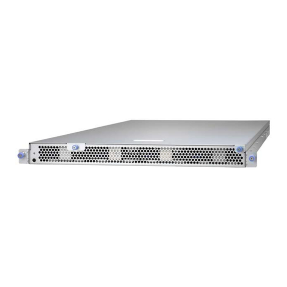
Leveraging advanced technology from Intel , the GT86A-B7051 server system is capable of offering scalable 32 and 64-bit computing, high bandwidth memory design, and lightning-fast PCI-E bus implementation. The GT86A-B7051 not only empowers your company in nowadays IT demand but also offers a smooth path for future application usage. -
Page 16: Features
Features TYAN GT86A B7051 (B7051G86AW12-1T-HE) Form Factor 1U Rackmount Chassis Model GT86A Dimension (D x W x System 33.86" x 17.32" x 1.72" (860 x 440 x 43.6mm) Motherboard B7051G86AW12-1T-HE Board Dimension CEB, 12"x10.5" (305x267mm) Front Panel Buttons (1) RST / (1) PWR w/ LED Type / Q'ty 3.5"... - Page 17 CE (DoC) Operating Temp. 10° C ~ 35° C (50° F~ 95° F) Non-operating Operating - 40° C ~ 70° C (-40° F ~ 158° F) Temp. Environment In/Non-operating 90%, non-condensing at 35° C Humidity RoHS RoHS 6/6 Compliant Yes http://www.tyan.com...
-
Page 18: Standard Parts List
Contains Installation CD (1) TYAN installation CD Standard Parts List This section describes GT86A-B7051 package contents and accessories. Open the box carefully and ensure that all components are present and undamaged. The product should arrive packaged as illustrated below. 1.4.1... -
Page 19: About The Product
Power Button with LED Reset Button 1.5.2 Front Panel Buttons Button State Description Turn on and off the system (Use a pin). State Color Behavior Power Power On Solid On Green Power Off Reset Press to reset the system. http://www.tyan.com... -
Page 20: System Rear View
1.5.3 System Rear View Power Supply LAN1 (I210, shared BMC) USB2.0 Ports VGA Port Serial Port (COM1) 10GB LAN Port Reset Button Power Button with LED ID Button http://www.tyan.com... -
Page 21: Internal View
1.5.4 Internal View (12) 3.5” SAS/SATA 6G HDD from LSI SAS2308 M7051G86-BP6-4 HDD Backplane Board (6) System Fans (1) 2.5” SATA 6G SSD from PCH Power supply http://www.tyan.com... - Page 22 NOTE http://www.tyan.com...
-
Page 23: Chapter 2: Setting Up
A grounding strap or an anti-static pad Most of the electrical and mechanical connections can be disconnected with your hands. It is recommended that you do not use pliers to remove connectors as it may damage the soft metal or plastic parts of the connectors. http://www.tyan.com... -
Page 24: Precautions
Working on a system that is connected to a power supply can be extremely dangerous. Follow the guidelines below to avoid damage to GT86A-B7051 or injury to yourself. Ground yourself properly before removing the top cover of the system. -
Page 25: Installing Motherboard Components
This section describes how to install components on to the motherboard, including CPUs, memory modules, HDD and PCI-E cards. 2.1.1 Removing the Chassis Cover Follow these instructions to remove the GT86A-B7051 chassis cover. Loosen the thumb screw on the front. Slide the top cover forward and then lift it up. http://www.tyan.com... -
Page 26: Installing The Cpu And Heatsink
Follow the steps below to install CPUs and CPU heatsinks. Locate the CPU sockets. Always start with CPU0 first. Pull the levers slightly away from the socket and then push them to a fully open position. Lift the CPU socket cover to a fully open position. http://www.tyan.com... - Page 27 Remove the protection cap from the CPU socket. Place the CPU into the socket making sure that the gold arrow is located in the right direction. Close the CPU socket cover. http://www.tyan.com...
- Page 28 Press the levers down to secure the CPU. Position the heatsink on top of the CPU and secure it with 4 screws. Repeat steps 2 to 8 to install the second CPU and heatsink. http://www.tyan.com...
-
Page 29: Installing The Memory
Align and insert the memory module down onto the slot. When inserted properly, the memory slot locking levers lock automatically on the indentations at the ends of the module. Follow the recommended memory population table to install the other memory modules. http://www.tyan.com... - Page 30 http://www.tyan.com...
-
Page 31: Installing Ssd And Hdd
2.1.4 Installing SSD and HDD The GT86A-B7051 can support up to (1) 2.5” OS SSD and up to (12) 3.5’’ hard drives or (12) 2.5” SSDs. Follow these instructions to install a hard drive. Pull the locking lever open and slide the SSD tray out. - Page 32 Use 4 screws securing the SSD to the SSD tray. Place the SSD tray into the chassis and push the locking lever to secure it. Connect the SATA power cable and SATA cable. Pull up the latch and slightly push backward to release the HDD tray. http://www.tyan.com...
- Page 33 Take out the HDD tray. Insert the blue rubber stub into the screw hole. Use four HDD screws in the AK box to secure the HDD to the tray. Place the HDD tray into the chassis. http://www.tyan.com...
-
Page 34: Rack Mounting
Sliding Rails x 2 Mounting Ears x 2 2.2.1 Installing the Server in a Rack Follow these instructions to mount the TYAN GT86A-B7051 into an industry standard 19" rack. NOTE: Before mounting the TYAN GT86A-B7051 in a rack, ensure that all internal components have been installed and that the unit has been fully tested. -
Page 35: Installing The Inner Rails To The Chassis
Installing the inner Rails to the Chassis Release and detach the inner rail from the sliding rail. Align the inner sliding rail on one side of the server. Pull the inner sliding rail forward to secure it to the chassis. http://www.tyan.com... - Page 36 Align the inner sliding rail on the other side of the server. http://www.tyan.com...
-
Page 37: Installing The Outer Rails To The Rack
2.2.2 Installing the Outer Rails to the Rack Secure the outer rails to the rack. http://www.tyan.com... -
Page 38: Rack Mounting The Server
2.2.3 Rack mounting the Server Lift the unit and then insert the inner slide rails into the middle rails. Push the whole system into the rack. Secure the whole system to the rack with 2 thumb screws. http://www.tyan.com... -
Page 39: Chapter 3: Replacing Pre-Installed Components
Chapter 3: Replacing Pre-Installed Components Introduction This chapter explains how to replace the pre-installed components, including the Motherboard, M7051G86-BP6-4 HDD Backplane Board, M7062-I599-1T OCP Card, System fan, Power supply unit etc. Disassembly Flowchart The following flowchart outlines the disassembly procedure. http://www.tyan.com... -
Page 40: Removing The Cover
Before replacing any parts you must remove the chassis cover. Follow Section 2.1.1 2.1.1 Removing the (page 25) to remove the cover of the Chassis Cover GT86A-B7051. Replacing Motherboard Components Follow these instructions to replace motherboard components, including the motherboard. 3.4.1 Disconnecting All Motherboard Cables Before replacing the motherboard or certain components, remove cables connected to the motherboard. - Page 41 http://www.tyan.com...
-
Page 42: Removing The Motherboard
After removing all of the aforementioned cables, follow the instructions below to remove the motherboard from the chassis. 1 Remove the heatsinks and processors if installed. 2 Remove the nine screws securing the motherboard to the chassis. 3 Carefully lift the motherboard from the chassis. http://www.tyan.com... -
Page 43: Replacing The Ocp Lan Card
Replacing the OCP LAN Card Follow these instructions to replace the OCP LAN Card. Unscrew the OCP LAN Card to replace with a new one. http://www.tyan.com... -
Page 44: Replacing The System Fan
Follow these instructions to replace the system fan. Disconnect the fan cable from the mainboard. Take out the failed fan. After replacing a new fan, follow Step 1 & 2 in reverse order to reinstall the fan. Connect the fan cable to the mainboard connector. http://www.tyan.com... -
Page 45: Replacing The Hdd Backplane Board
Unscrew the HDD BP Board. Take out the failed HDD BP Board and replace with a new one. Screw the HDD BP Board to the chassis and connect the power cable and Mini SAS cable to the HDD BP Board. http://www.tyan.com... -
Page 46: M7051G86-Bp6-4 Hdd Bp Board Specifications
380x17 mm, 4-layer PCB (4) SAS Connector connect to HDD (J1/J2/J4/J5) Integrated I/O (1) MINI SAS Connector connect to MB (J3) (1) 4-pin power connector (PW2) J1/J2/J4/J5: SAS Connector VDD_5_RUN VDD_5_RUN VDD_5_RUN VDD_12_RUN VDD_12_RUN VDD_12_RUN SAS_TX+ SAS_TX- SAS_RXBN SAS_RXBP http://www.tyan.com... - Page 47 J3: Mini SAS Connector SAS_TX0+ SAS_TX0- SAS_TX1+ SAS_TX1- SAS_TX2+ SAS_TX2- SAS_TX3+ SAS_TX3- SAS_RXBP0 SAS_RXBN0 SAS_RXBP1 SAS_RXBN1 SAS_RXBP2 SAS_RXBN2 SAS_RXBP3 SAS_RXBN3 http://www.tyan.com...
-
Page 48: Replacing The Power Supply
Replacing the Power Supply Follow these instructions to replace the power supply. Disconnect all power cables. Unscrew the power supply. http://www.tyan.com... - Page 49 Take out the power supply. After replacing a new power supply, follow Step 1~3 in reverse order to reinstall the power supply. Connect the power cables and the SATA cable to the HDD BP Board and the Mainboard. http://www.tyan.com...
- Page 50 NOTE http://www.tyan.com...
-
Page 51: Chapter 4: Motherboard Information
Caution! To avoid damaging the motherboard and associated components, do not use torque force greater than 7kgf/cm (6.09 lb/in) on each mounting screw for motherboard installation. Do not apply power to the board if it has been damaged. http://www.tyan.com... -
Page 52: Board Image
Board Image S7051 This picture is representative of the latest board revision available at the time of publishing. The board you receive may not look exactly like the above picture. http://www.tyan.com... -
Page 53: Block Diagram
Block Diagram S7051 Block Diagram http://www.tyan.com... -
Page 54: Motherboard Mechanical Drawing
Motherboard Mechanical Drawing http://www.tyan.com... -
Page 55: Board Parts, Jumpers And Connectors
The board you receive may not look exactly like the above diagram. The DIMM slot numbers shown above can be used as a reference when reviewing the DIMM population guidelines shown later in the manual. For the latest board revision, please visit our web site at http://www.tyan.com. http://www.tyan.com... - Page 56 Chassis Intrusion Header LED1 ID LED LED2 BMC Heartbeat LED LED23 SAS LED LED24 SAS LED ID LED Switch button Reset button J5011 Power button Jumper Legend OPEN - Jumper OFF Without jumper cover CLOSED - Jumper ON With jumper cover http://www.tyan.com...
- Page 57 http://www.tyan.com...
- Page 58 Short: Use this header to disable the system chassis intrusion alarm. Short (Default) J39: Front Panel Header Signal Signal PWRLED+ V3P3_AUX IDLED+ PWRLED- IDLED- HDD_LED+ SYS_FAULT1- HDD_LED- SYS_FAULT2- PWR_SW# LAN1LED+ LAN1LED- RESET SW# SMBDATA SMBCLK IDLED_SW# INTRUSION# NMI_SW# http://www.tyan.com...
- Page 59 http://www.tyan.com...
- Page 60 3. Move the jumper cap to close Pin_2 and Pin_3 for several seconds to Clear CMOS. 4. Put jumper cap back to Pin_1 and Pin_2 (Default setting). 5. Reconnect power connectors to the motherboard and power on Clear CMOS system. http://www.tyan.com...
- Page 61 LED2 LED1 LED24 LED23 http://www.tyan.com...
- Page 62 LED SAS/SATA Controller not error SAS/SATA Controller error J30: SATA SGPIO Header for BB HD Board Signal Signal SMBCLK SATA_DATAOUT1 SMBDATA SATA_DATAOUT0 SLOAD SCLOCK VCC3_AUX BMC_HDD_FAULT J24: Vertical Type-A USB Connector Signal USB 5V Power USB Data- USB Data+ http://www.tyan.com...
- Page 63 J31/J36 http://www.tyan.com...
- Page 64 J68: Flash Security Override Header Signal V3P3_AUX AUD_AZA_SD0 J22: PCH Software RAID KEY Header PIN1 Signal PCH_RAID_KEY J33: SAS SMB Connector Signal Signal VCC3_AUX BMC_SMB_CLK3 BMC_SMB_DAT3 BMC_HDD_FAULT J69: ME Recovery Mode Jumper Pin 1-2 Closed: Normal Mode (Default) Pin 2-3 Closed: Recovery http://www.tyan.com...
-
Page 65: Thermal Interface Material
CPU lid (applying too much will actually reduce the cooling). NOTE: Always check with the manufacturer of the heat sink & processor to ensure that the thermal interface material is compatible with the processor and meets the manufacturer’s warranty requirements. http://www.tyan.com... -
Page 66: Tips On Installing Motherboard In Chassis
If there are any studs missing, you will know right away since the motherboard will not be able to be securely installed. http://www.tyan.com... - Page 67 Some chassis include plastic studs instead of metal. Although the plastic studs are usable, MiTAC recommends using metal studs with screws that will fasten the motherboard more securely in place. Below is a chart detailing what the most common motherboard studs look like and how they should be installed. http://www.tyan.com...
-
Page 68: Installing The Memory
Installing the Memory Before installing memory, ensure that the memory you have is compatible with the motherboard and processor. Check the TYAN Web site at http://www.tyan.com details of the type of memory recommended for your motherboard. The following pictures show common types of DDR3 memory modules. - Page 69 4. Dual-rank DIMMs are recommended over single-rank DIMMs. 5. Un-buffered DIMM can offer slightly better performance than registered DIMM if populating only a single DIMM per channel. 6. Always install with CPU0 Socket and DIMM_A0 Slot first, following the alphabetical order. http://www.tyan.com...
- Page 70 √ √ √ √ √ √ CPU1_DIMM_A0 √ √ √ CPU1_DIMM_A1 √ √ √ √ √ √ √ √ CPU1_DIMM_B0 √ √ CPU1_DIMM_B1 √ √ √ √ √ √ CPU1_DIMM_C0 √ CPU1_DIMM_C1 √ √ √ √ CPU1_DIMM_D0 √ CPU1_DIMM_D1 http://www.tyan.com...
-
Page 71: Finishing Up
In the rare circumstance that you have experienced difficulty, you can find help by asking your vendor for assistance. If they are not available for assistance, please find setup information and documentation online at our website or by calling your vendor’s support line. http://www.tyan.com... - Page 72 NOTE http://www.tyan.com...
-
Page 73: Chapter 5: Bios Setup
The table below shows how to navigate in the setup program using the keyboard. Function Left/Right Arrow Keys Select Screen Up/Down Arrow Keys Select Item Enter Select Change opt. General Help Previous Value Optimized Defaults Save & Exit Exit http://www.tyan.com... - Page 74 The following pages provide the details of BIOS menu. Please be noticed that the BIOS menu are continually changing due to the BIOS updating. The BIOS menu provided are the most updated ones when this manual is written. Please visit TYAN’s website at http://www.tyan.com for the information of BIOS updating. http://www.tyan.com...
-
Page 75: Main Menu
It displays BIOS related information. Memory Information This displays the total memory size. System Date Adjust the system date. MM (Months): DD (Days): YYYY (Years) System Time Adjust the system clock. HH (24 hours format): MM (Minutes): SS (Seconds) Access Level Read only. http://www.tyan.com... -
Page 76: Advanced Menu
This section facilitates configuring advanced BIOS options for your system. PCI Subsystem Settings PCI, PCI-X and PCI Express Settings. ACPI Settings System ACPI Parameters. Trusted Computing Trusted Computing Settings. CPU Configuration CPU Configuration Parameters. Runtime Error Logging Runtime Error Logging Support Setup Options SATA Configuration SATA Devices Configuration. http://www.tyan.com... - Page 77 PCIe Slot Configuration PCIe Slot Configuration. USB Configuration USB Configuration Parameters. Info Report Configuration Info Report Configuration. Hardware Health Configuration Hardware health Configuration Parameters. Super IO Configuration System Super IO Chip Parameters. Serial Port Console Redirection Serial Port Console Redirection. http://www.tyan.com...
-
Page 78: Pci Subsystem Settings
Enables or Disables 64bit capable Devices to be Decoded in Above 4G Address Space (Only if System Supports 64 bit PCI Decoding). Disabled / Enabled Single Root I/O Virtualization Enable or disable Single Root I/O Virtualization. Enabled / Disabled http://www.tyan.com... -
Page 79: Acpi Settings
Enable or disable System ability to Hibernate (OS/S4 Sleep State). This option may not be effective with some OS. Disabled / Enabled ACPI Sleep State Select the highest ACPI sleep state the system will enter when the SUSPEND button is pressed. S1 only (CPU Stop Clock) / Suspend Disabled http://www.tyan.com... -
Page 80: Trusted Computing
5.3.3 Trusted Computing Security Device Support Enables or Disables BIOS support for security device. O.S. will not show Security Device. TCG EFI protocol and INTIA interface will not be available. Disabled / Enabled http://www.tyan.com... -
Page 81: Cpu Configuration
Enabled / Disabled Active Processor Cores Number of cores to enable in each processor package. All / 1 / 2 / 3 / 4 / 5 / 6 / 7 Limit CPUID Maximum Disabled for Windows XP. Disabled / Enabled http://www.tyan.com... - Page 82 Intel Virtualization Technology When enabled, a VMM can utilize the additional hardware capabilities provided by Vanderpool Technology. NOTE: Once the lock bit is set, the contents of this register can not be modified until S5 reset occurs. Enabled / Disabled http://www.tyan.com...
- Page 83 5.3.4.1 Socket 0 CPU Information Read only. http://www.tyan.com...
- Page 84 Custom / Disabled / Energy Efficient EIST Enable/Disable Intel StepSpeed. Disabled / Enabled Turbo Mode Enable/Disable Turbo Mode. Enabled / Disabled P-STATE Coordination Change P-State coordination type. HW_ALL / Disabled CPU C3 Report Enable/Disable CPU C3 (ACPI C2) report to OS. Disabled / Enabled http://www.tyan.com...
- Page 85 Long duration power limit in Watts. Factory Long Duration Maintained Read only. Long Duration Maintained Time window which the long duration power is maintained. Recommended short duration power limit Read only. Short duration power limit Short duration power limit in Watts. http://www.tyan.com...
-
Page 86: Runtime Error Logging
5.3.5 Runtime Error Logging Runtime Error Logging Support Enable/Disable Runtime Error Logging Support. Disabled / Enabled http://www.tyan.com... -
Page 87: Sata Configuration
Port 0 / 1 / 2 / 3 / 4 / 5 Hot Plug Enable/Disable SATA Ports Hot Plug Support. Enabled / Disabled Port 0 / 1 / 2 / 3 / 4 / 5 Staggered Spin-up AHCI Supports Staggered Spin-up. Disabled / Enabled http://www.tyan.com... -
Page 88: Onboard Device Configuration
Enabled/Disabled the VGA in the Chipset. Enabled / Disabled LAN (I210) Enabled/Disabled the LAN in the Chipset. Enabled / Disabled LAN1 OPROM Enabled/Disabled the LAN Option ROM in the Chipset. Disabled / PXE LSI2308 OPROM Enabled/Disabled LSI2308 OPROM in the Chipset. Disabled / PXE http://www.tyan.com... -
Page 89: Usb Configuration
Maximum time the device will take before it properly reports itself to the Host Controller. AUTO uses default value: for a Root port it is 100 ms, for a Hub port the delay is taken from Hub descriptor. Auto / Manual http://www.tyan.com... -
Page 90: Info Report Configuration
0 / 1 / 2 / 3 / 4 / 5 / 6 / 7 / 8 / 9 / 10 / Until Press ESC Info Error Message Info Error Message Support enabled/disabled. Disabled / Enabled Summary Screen Summary Screen Support enabled/disabled. Disabled / Enabled http://www.tyan.com... -
Page 91: 5.3.10 Hardware Health Configuration
Select [Disabled] to allow the fan speed running FULL ON. Disabled / Enabled 5.3.11.1 Sensor Data Register Monitoring When you enter the Sensor Data Register Monitoring submenu, you will see the following dialog window pop out. Please wait 8~10 seconds. http://www.tyan.com... - Page 92 NOTE: SDR can not be modified. Read only. http://www.tyan.com...
-
Page 93: 5.3.11 Super Io Configuration
5.3.11 Super IO Configuration Super IO Chip Read only. http://www.tyan.com... - Page 94 / IO=2F8h; IRQ=3, 4, 5, 6, 7, 9, 10, 11, 12; / IO=3E8h, IRQ=3, 4, 5, 6, 7, 9, 10, 11, 12; / IO=2E8h, IRQ=3, 4, 5, 6, 7, 9, 10, 11, 12; Change Settings SUART clock source. 24MHZ/13 / 24MHz http://www.tyan.com...
-
Page 95: 5.3.12 Serial Port Console Redirection
Console Redirection Settings The settings specify how the host computer (which the user is using) will exchange data. Both computers should have the same or compatible settings. NOTE: Console Redirection Settings submenu appears when Console Redirection is set to [Enabled]. http://www.tyan.com... - Page 96 0 if the num of 1’s in the data bits is even. Odd: parity bit is 0 if the num of 1’s in the data bits is odd. Mark: parity bit is always 1. Space: parity bit is always 0. Mark and Space parity do not allow for error detection. None / Even / Odd / Mark / Space http://www.tyan.com...
- Page 97 Disabled / Enabled Legacy OS Redirection Resolution On Legacy OS, the number of rows and columns supported redirection. 80x24 / 80x25 Putty KeyPad Select FunctionKey and KeyPad on Putty. VT100 / LINUX / XTERMR6 / SCO / ESCN / VT400 http://www.tyan.com...
- Page 98 VT-UTF8 / VT100 / VT100+ / ANSI Bits per Second Select serial port transmission speed. The speed must be matched on the other side. Long or noisy lines may require lower speeds. 115200 / 9600 / 19200 / 38400 / 57600 http://www.tyan.com...
- Page 99 ‘stop’ signal can be sent to stop the data flow. Once the buffers are empty, a ‘start’ signal can be sent to restart the flow. Hardware flow control uses two wires to send start/stop signal. None / Hardware RTS/CTS Data Bits / Parity / Stop Bits Read only. http://www.tyan.com...
-
Page 100: Chipset Menu
Chipset Menu North Bridge North Bridge Parameters. South Bridge South Bridge Parameters. WatchDog Timer Configuration WatchDog Configuration. http://www.tyan.com... -
Page 101: North Bridge
HIDE / UNHIDE MPST Support Enable or Disable MPST Support. Along with enabling MPST Support, it also requires NUMA to be enabled and Channel Interleaving to be set to 1-way for MPST tables to be published. Disabled / Enabled http://www.tyan.com... - Page 102 DDR Speed Force DDR Speed. Auto / Force DDR3 800 / Force DDR3 1066 / Force DDR3 1333 / Force DDR3 1600 http://www.tyan.com...
- Page 103 With Manual option user can force the PCI resource allocation across multiple IOHs based on the ratios selected. Auto / Manual No Snoop Optimization This configuration requires that No Snoop in PCI Express Settings is enabled. It is recommended that this option is left at default (VC1). VC1 / VC0/VCP/VC1 http://www.tyan.com...
- Page 104 Select number of 1GB contiguous regions to be assigned MMIOH space per CPU. 64G / 1G / 2G / 4G / 8G / 16G / 32G / 128G MMCFG Base Select the MMCFG BASE Values. 0x80000000 / 0xA0000000 / 0xC0000000 http://www.tyan.com...
- Page 105 Disabled / Enabled ® NOTE: The following items will appear when Intel VT-d is set to [Enabled]. Coherency Support Enable/Disable VT-d Engine Coherency Support. Disabled / Enabled ATS Support Enable/Disable VT-d Engine Address Translation Services support. Enabled / Disabled http://www.tyan.com...
- Page 106 5.4.1.2 DIMM Information Read only. http://www.tyan.com...
-
Page 107: South Bridge
Power Off / Power On / Last State SLP_S4 Assertion Stretch Enable Enabled/Disabled SLP_S4# Assertion Stretch. Enabled / Disabled SLP_S4 Assertion Width Select a minimum assertion width of the SLP_S4# signal. 4-5 Seconds / 1-2 Seconds / 2-3 Seconds / 3-4 Seconds http://www.tyan.com... -
Page 108: Watchdog Timer Configuration
Disabled / POST / OS / PowerOn NOTE: Watch Dog Timer will not appear when Watch Dog Mode is set to [Disabled]. Watch Dog Timer Watch Dog Timer Help. 2 MINS / 4 MINS / 6 MINS / 8 MINS / 10 MINS http://www.tyan.com... -
Page 109: Boot
Select display mode for Option ROM. Force BIOS / Keep Current INT 19 Trap Response BIOS reaction on INT19 trapping by option ROM: IMMEDIATE - execute the trap right away; POSTPONED - execute the trap during legacy boot. Immediate / Postponed http://www.tyan.com... - Page 110 Endless Boot Enable or disable Endless Boot. Disabled / Enabled Boot Option Priorities Boot Option #1 Select the first/second boot device. Device Name / Disabled http://www.tyan.com...
-
Page 111: Csm Parameters
Control the execution of UEFI and Legacy Storage OpROM. Do not Launch / UEFI only / Legacy only Launch Video OpROM policy Control the execution of UEFI and Legacy Video OpROM. Do not Launch / UEFI only / Legacy only http://www.tyan.com... - Page 112 Other PCI device ROM priority For PCI devices other than Network, Mass storage or Video defines which OpROM to launch. UEFI OpROM / Legacy OpROM http://www.tyan.com...
-
Page 113: Delete Boot Option
5.5.2 Delete Boot Option Delete Boot Option Remove an EFI boot option from the boot order. Select one to delete / UEFI: Built-in EFI Shell http://www.tyan.com... -
Page 114: Security
Confirm New Password window will pop out to ask for confirmation. User Password Set user password in the Create New Password window. After you key in the password, the Confirm New Password window will pop out to ask for confirmation. http://www.tyan.com... -
Page 115: Secure Boot Menu
Secure Boot can be enabled if 1. System running in User mode with enrolled Platform Key (PK) 2. CSM function is disabled. Enabled / Disabled Secure Boot Mode Secure Boot mode selector. “Custom” Mode allows for more flexibility changing Image Execution policy and Secure Boot Key management. Standard / Custom http://www.tyan.com... -
Page 116: Key Management
Insert factory default key(s) or load a file formatted as 1. EFI Variable as Time-Based Authenticated Header or 2. Key Certificate list starting with EFI_SIGNATURE_LIST Header or Single Key Certificate in X509_DER, RSA2048_DER or SHA256_BIN format. Delete KEK Delete the Variable from NVRAM. Removing PK will reset System to Setup Mode. http://www.tyan.com... - Page 117 Single Key Certificate in X509_DER, RSA2048_DER or SHA256_BIN format. Append DBX Insert factory default key(s) or load a file formatted as 1. EFI Variable as Time-Based Authenticated Header or 2. Key Certificate list starting with EFI_SIGNATURE_LIST Header or Single Key Certificate in X509_DER, RSA2048_DER or SHA256_BIN format. http://www.tyan.com...
-
Page 118: Server Management
Server Management Press <Enter> to change the SEL event log configuration. Enable/Disable interfaces to communicate with BMC. http://www.tyan.com... -
Page 119: System Event Log
Choose options for reactions to a full SEL. Do Nothing / Erase Immediately Log EFI Status Codes Disable the logging of EFI Status Codes or log only error code or only progress code or both. Both / Disabled / Error Code / Progress Code http://www.tyan.com... -
Page 120: Bmc Network Configuration
BMC). Unspecified option will not modify any BMC network parameters during BIOS phase. Unspecified / Static / Dynamic-Obtained by BMC Station IP Address / Subnet Mask / Station MAC Address / Router IP Address / Router MAC Address Read only. http://www.tyan.com... -
Page 121: Event Logs
Event Logs Read only. http://www.tyan.com... -
Page 122: Save & Exit
Save Changes and Reset Reset the system after saving the changes. Discard Changes and Reset Reset system setup without saving any changes. Save Options Read only. Save Changes Save changes done so far to any of the setup options. http://www.tyan.com... - Page 123 Restore Defaults Restore/Load Default values for all the setup options. Save as User Defaults Save the changes done so far as User Defaults. Restore User Defaults Restore the User Defaults to all the setup options. Boot Override Read only. http://www.tyan.com...
- Page 124 NOTE http://www.tyan.com...
-
Page 125: Chapter 6: Diagnostics
BIOS flash failure, you must contact your dealer for a replacement BIOS. There are no exceptions. TYAN does not have a policy for replacing BIOS chips directly with end users. In no event will TYAN be held responsible for damages done by the end user. -
Page 126: Amibios Post Code (Aptio)
South Bridge initialization before microcode loading 0x05 OEM initialization before microcode loading 0x06 Microcode loading 0x07 AP initialization after microcode loading 0x08 North Bridge initialization after microcode loading 0x09 South Bridge initialization after microcode loading 0x0A OEM initialization after microcode loading 0x0B Cache initialization http://www.tyan.com... - Page 127 CPU post-memory initialization is started. 0x33 CPU post-memory initialization. Cache initialization 0x34 CPU post-memory initialization. Application Processor(s) (AP) initialization 0x35 CPU post-memory initialization. Boot Strap Processor (BSP) selection 0x36 CPU post-memory initialization. System Management Mode(SMM) initialization 0x37 Post-Memory North Bridge initialization is started. http://www.tyan.com...
- Page 128 Reserved for future AMI progress codes S3 Resume Error Codes 0xE8 S3 Resume failed 0xE9 S3 Resume PPI not found 0xEA S3 Resume Boot Script error 0xEB S3 OS wake error 0xEC – 0xEF Reserved for future AMI error codes http://www.tyan.com...
- Page 129 CPU DXE initialization (CPU module specific) 0x67 CPU DXE initialization (CPU module specific) 0x68 PCI host bridge initialization 0x69 North Bridge DXE initialization is started. 0x6A North Bridge DXE SMM initialization is started. 0x6B North Bridge DXE initialization (North Bridge module specific) http://www.tyan.com...
- Page 130 USB initialization is started. 0x9B USB Reset 0x9C USB Detect 0x9D USB Enable 0x9E -0x9F Reserved for future AMI codes 0xA0 IDE initialization is started 0xA1 IDE Reset 0xA2 IDE Detect 0xA3 IDE Enable 0xA4 SCSI initialization is started. http://www.tyan.com...
- Page 131 No Console Output Devices are found. 0xD7 No Console Input Devices are found. 0xD8 Invalid password 0xD9 Error loading Boot Option (LoadImage returned error) 0xDA Boot Option is failed (StartImage returned error). 0xDB Flash update is failed. 0xDC Reset protocol is not available. http://www.tyan.com...
- Page 132 System is waking up from the S3 sleep state. 0x40 System is waking up from the S4 sleep state. 0xAC System has transitioned into ACPI mode. Interrupt controller is in APIC mode. 0xAA System has transitioned into ACPI mode. Interrupt controller is in APIC mode. http://www.tyan.com...
-
Page 133: Appendix I: Cable Connection Tables
→ Fan6 2. Mini-SAS Cables M7051G86-BP6-4 BP to S7051 MB M7051G86-BP Cable Connect to S7051 → Mini-SAS CABLE → Mini-SAS CABLE → Mini-SAS CABLE 3. SATA Cable M7051G86-BP6-4 BP to S7051 MB Cable Connect to S7051 → SATA CABLE http://www.tyan.com... - Page 134 J39(PIN11,13) → Reset Cable Reset SW J39 (PIN15,17) 5. Power Supply Cables PSU to S7051 MB Connect to S7051 → → → → PSU to M7051G86-BP6-4 BP Connect to M7051G86-BP6-4 → B4P P3 → B4P P4 → B4P P5 http://www.tyan.com...
-
Page 135: Appendix Ii: Fan And Temp Sensors
This section aims to help readers identify the locations of some specific FAN and Temp Sensors on the motherboard. A table of BIOS Temp sensor name explanation is also included for readers’ reference. NOTE: The red dot indicates the sensor. http://www.tyan.com... - Page 136 (rpm) Temp Sensor: PCH_Area_Temp, SAS_Area_Temp and M/B_Inlet_Temp. They detect the system temperature around. NOTE: The system temperature is measured in a scale defined by Intel, not in Fahrenheit or Celsius. BIOS Temp Sensor Name Explanation: http://www.tyan.com...
- Page 137 Temperature of CPU0_DIMM_A1 Slot CPU0_DIMM_B0 Temperature of CPU0_DIMM_B0 Slot CPU0_DIMM_B1 Temperature of CPU0_DIMM_B1 Slot CPU0_DIMM_C0 Temperature of CPU0_DIMM_C0 Slot CPU0_DIMM_C1 Temperature of CPU0_DIMM_C1 Slot CPU0_DIMM_D0 Temperature of CPU0_DIMM_D0 Slot CPU0_DIMM_D1 Temperature of CPU0_DIMM_D1 Slot CPU1_DIMM_A0 Temperature of CPU1_DIMM_A0 Slot http://www.tyan.com...
- Page 138 Temperature of CPU1_DIMM_D1 Slot BIOS FAN Sensor Name Explanation SYS_FAN_1 Fan speed of SYS_FAN_1 SYS_FAN_2 Fan speed of SYS_FAN_2 SYS_FAN_3 Fan speed of SYS_FAN_3 SYS_FAN_4 Fan speed of SYS_FAN_4 SYS_FAN_5 Fan speed of SYS_FAN_5 SYS_FAN_6 Fan speed of SYS_FAN_6 http://www.tyan.com...
-
Page 139: Appendix Iii: Fru Parts Table
Appendix III: FRU Parts Table GT86A-B7051 FRU Parts Item Model Number Part Number Picture Description MINI-SAS CABLE,SHORT MINI-SAS 36P/SHORT MINI-SAS CCBL-0688 422797000003 36P,L=800MM,TN70-B7016-X2 SAS INTERNAL,1000 mm,MINI-SAS CABLE,SHORT FRU-CS-0220 422T42300011 MINI-SAS 36P/SHORT MINI-SAS 36P SATA CABLE(SAS WIRE),7P 180°/7P 180°,L=900MM CCBL-033V 422794300003... - Page 140 NOTE http://www.tyan.com...
-
Page 141: Appendix Iv: Gt86A-B7051 Skus
Appendix IV: GT86A-B7051 SKUs Customer Product Product Name Product Configuration System Fan Name CPU: Intel®Xeon E5-2620 v2 *2 DIMM: Samsung R-DDR3L 16GB *8 BS7051G86AW8-1T-HE Config DH OS SSD: Sandisk SD7SB6S 256G / Intel® 530 240GB *1 Data HDD: 3.5" WD 4TB HDD *8 CPU: Intel®Xeon... - Page 142 CPU: Intel®Xeon E5-2620 v2 *2 DIMM: Samsung R-DDR3L 16GB *8 OS SSD: Sandisk X300 BS7051G86AW6-1T-HE-DJ Config DJ 256G / Intel® 530 240GB *1 Data SSD: 2.5" Sandisk X300s 1TB SSD / Samsung SSD 960GB http://www.tyan.com...
-
Page 143: Appendix V: Technical Support
By offering plenty of options for users, MiTAC serves multiple market segments with the industry’s most competitive services to support them. Please feel free to contact us directly for this service at tech-support@tyan.com Help Resources: 1. See the beep codes section of this manual. - Page 144 (RMA) number. The RMA number should be prominently displayed on the outside of the shipping carton and the package should be mailed prepaid. TYAN will pay to have the board shipped back to you. TYAN® GT86A-B7051 Service Engineer’s Manual V1.0 Document No.: D2296-100 http://www.tyan.com...
Need help?
Do you have a question about the GT86A-B7051 and is the answer not in the manual?
Questions and answers