
Related Manuals for elco Firebird FB 4 R LN


Summary of Contents for elco Firebird FB 4 R LN
- Page 1 FB 4 R LOW NOx LIGHT OIL BURNER Instructions to Assembly, Commissioning and Maintenance Before installing and using the burner, read this manual carefully and keep it close to the burner.
- Page 2 RANGE This manual refers to the following products: BURNER MODEL FIREBIRD CODE ELCO CODE FB 4 R 20 LN 414949 3146467 FB 4 R 26 LN...
-
Page 3: Table Of Contents
CONTENTS 1 SAFETY Overview ..............5 Intended use. - Page 4 5 COMMISSIONING Safety during commissioning ..........30 Checks before commissioning .
-
Page 5: Safety
SAFETY SAFETY 1 .1 Overview These instructions for the installation, commissioning and maintenance of the burner are for use by technicians from professional heating companies that are qualified to carry out these activities. The instructions contain indications and information on how to move, handle, activate, adjust, maintain and remove the appliance and how to dispose of the components at the end of the their useful life. -
Page 6: Symbols Used
SAFETY 1 .3 Symbols used 1 .3 .1 Key to symbols used in the manual DANGER Maximum danger. Indicates operations that cause serious injury, death or long-term health risks if performed incorrectly. DANGER DANGER DANGER Indicates a dangerous situation that could cause serious injury, death or long-term health risks, caused by electricity, if handled without due care or incorrectly. -
Page 7: Requirements For Personnel Or Operators
SAFETY 1 .4 Requirements for personnel or operators CAUTION It may be hazardous to assign activities to personnel that are not sufficiently qualified. It may CAUTION harm the operators themselves if they perform manoeuvres or operations incorrectly, with a serious impact on personal safety, things and property. CAUTION Installation, commissioning and maintenance activities must only be carried out by the personnel of dedicated heating companies specifically qualified to perform these tasks. -
Page 8: General
GENERAL GENERAL 2 .1 Burner description FB 4 R LN is a latest generation single-stage burner fuelled by light oil. The innovative combustion head ensures low NOx and CO emissions within the emission limits set out by European Regulations for energy related products (ErP). The burner uses functional components that, in addition to ensuring a long working life, also allow for easy installation, adjustment and maintenance. -
Page 9: Identification
GENERAL 2 .3 Identification Check the identification label of the burner (“Fig. 1”). 414852|BRNxxxELN|3146166|SN0000 000001|SL005600012345|DH31/07/201 8 12.17.58 414949 3146467 31-18 BRNxxxELN FB 4 R 20 LN 20,6 kg/h 1,72 1N-230 IPxx FUEL LIGHT OIL Visc. @ 20 °C 1,6-6 mm²/s WEIGHT 0000000001 Made in Italy... -
Page 10: Structure
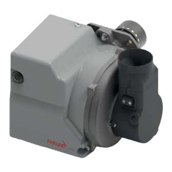
GENERAL 2 .4 Structure 2 .4 .1 Structure of the burner Power indication LED Air valve indicator Connection PLUG-IN between control Housing for internal rotor box and ignition transformer Snorkel Reset button Air setting Control box Air intake Fig. 2 10/56... - Page 11 GENERAL Combustion head Extended pressure port Burner fixing bolt Burner base Burner flange (supplied) Oil pressure regulator 7 pin plug Fuel-oil pump Electric motor for pump and fan Solenoid valve Capacitor Ignition transformer Fig. 3 11/56...
-
Page 12: Structure Of The Combustion Head
GENERAL 2 .4 .2 Structure of the combustion head Combustion head Electrode group fixing screw Diffuser Combustion head fixing screw Electrode group Nozzle Diffuser fixing screw Fig. 4 12/56... -
Page 13: Control Box
GENERAL 2 .5 Control box The EBR-M4 control box, controls and monitors the forced draught burner. The microprocessor- controlled program sequence ensures maximum stability of time periods, regardless of fluctuations in the power supply or ambient temperature. The design of the control box protects it from the effects of flame outs. Whenever the supply voltage drops below its rated minimum level (170 ±... -
Page 14: Controlled Shutdown
GENERAL 2 .6 .2 Controlled shutdown – Boiler temperature control interrupts heat request. – The fuel-oil solenoid valve closes and the flame is extinguished. – The post-ventilation starts: time factory-set at 15 s. After the burner motor switches off. – Burner enters standby. 2 .6 .3 Safety function A safety shutdown occurs:... -
Page 15: Technical Data
TECHNICAL DATA TECHNICAL DATA 3 .1 Dimensions and weights Ø75 Ø 175 Ø 151,5 Ø 126,5 15 Max Øi 100 Fig. 7 Weight (kg) Model with packaging FB 4 R 20 LN FB 4 R 26 LN FB 4 R 35 LN 3 0 0 All measurements are given in millimetres. -
Page 16: Technical Data
TECHNICAL DATA 3 .2 Technical data FB 4 R 20 LN FB 4 R 26 LN FB 4 R 35 LN 20,6 kW 26,8 kW 36 kW Burner output factory setting 17.716 kcal/h 23.048 kcal/h 30.960 kcal/h Oil throughput factory setting 1,72 kg/h 2,23 kg/h 3,0 kg/h... -
Page 17: Electrical Diagram
TECHNICAL DATA 3 .3 Electrical diagram CONTROL BOX EBR-M4 R 15-15 B4 S3 T2 T1 B4 S3 T2 T1 HLF HLB ~50 Hz 230 V Ignition transformer Heater Photo-resistor STC Heater thermostat YVg Oil solenoid valve STS Safety thermostat MV Fan motor General switch with fuse HLB Security light HLF Operating light... -
Page 18: Installation
INSTALLATION INSTALLATION 4 .1 Safety during assembly DANGER Danger of death! - Contact with live electrical components may cause serious incidents. - Only professionally-trained and qualified personal can operate on the electrical system. - Before any operation, switch off the power supply to the system by operating the main switch. Check there is no power and ensure restart is impossible. -
Page 19: Installation Area
INSTALLATION 4 .2 Installation area Before installation, make sure that the installation area satisfies the following requirements: – operating temperature between +5°C and +45°C – dry, frost resistant, well-ventilated – no accumulation of heavy powders – no high levels of humidity –... -
Page 20: Preliminary Checks Before Mounting The Burner
INSTALLATION 4 .4 Preliminary checks before mounting the burner Before mounting the burner onto the boiler: – check the distance between tips of electrodes (2 mm) Fig. 10 – Check the position of the electrodes assuring that they are centered as shown in “Fig. 11”. A-A 1 : 1 Fig. -
Page 21: Burner Assembly
INSTALLATION 4 .5 Burner assembly CAUTION Install the burner on the boiler according to the installation position shown in “Fig. 12”. CAUTION Installation 2,3 and 4 are forbidden for safety reason. Fig. 12 The burner is secured to the boiler using the connection flange supplied with the burner. Follow the instructions below: –... - Page 22 INSTALLATION – position the flange (2), with the screw (1) facing upwards, onto the boiler and secure it with the nuts (5) supplied – tighten the nuts (5) of the flange evenly and diagonally with a tightening torque of 3,5 Nm max .
-
Page 23: Oil Systems
INSTALLATION – insert the air intake pipe (8) and secure it using a pipe clamp (9), not supplied Fig. 16 4 .6 Oil systems FUEL LEAKS - Fuel leaks may cause fire to break out. - They may be toxic via inhalation and cause skin irritation. CAUTION - Act swiftly to remove the cause of the leak. -
Page 24: Hydraulic Diagram
INSTALLATION 4 .6 .1 Hydraulic diagram Pressure Suction Return Bypass screw Pressure gauge port Diaphragm Pressure adjustment Nozzle outlet Return outlet Filter Suction inlet NC Valve Pressure regulator Constriction Vacuum gauge port Fig. 17 4 .6 .2 Oil pump Fuel-oil solenoid valve Suction connection Solenoid valve electrical connection Return connection... - Page 25 INSTALLATION • Two-pipe system (standard) The pump is supplied for operation with two pipes. To apply the fuel delivery pipe, proceed as follows: – remove the plastic cap (9) and screw in the delivery pipe (10) supplied with the burner. To apply the fuel return pipe, proceed as follows: –...
-
Page 26: Oil Feed And Suction Line With Two-Pipe System
INSTALLATION 4 .6 .3 Oil feed and suction line with two-pipe system Burner lower than tank H = x-y Fig. 20 Pipe length (m) Pipe length (m) H (m) H (m) Ø6 mm Ø8 mm Ø10 mm Ø6 mm Ø8 mm Ø10 mm CAUTION - X <... -
Page 27: Electrical Connection
INSTALLATION 4 .7 Electrical connection DANGER Danger of death caused by live components! Contact with live parts can lead to serious injury, take the following precautions: - ensure that the power is switched off for all electrical parts - electrical wiring installation must be carried out by qualified personnel and in compliance with the regulations currently in force in the country of destination. -
Page 28: Removing The Burner
INSTALLATION 4 .8 Removing the burner DANGER Danger of death caused by live components! Before carrying out any operations on the burner, operate the main power switch for the system to cut off the power supply. If it becomes necessary to remove the burner, proceed as follows: –... - Page 29 INSTALLATION – drain any fuel still inside the burner and in the fuel delivery pipe and collect it in a basin – loosen the pipe clamp (7) and remove the air intake pipe (8), if present Fig. 25 – loosen the nut (9) securing the burner to the boiler and, rotating the burner (10) slightly to the right, slide it off the boiler.
-
Page 30: Commissioning
COMMISSIONING COMMISSIONING 5 .1 Safety during commissioning CAUTION It may be hazardous to assign activities to personnel that are not sufficiently qualified. It may harm the operators themselves if they perform manoeuvres or operations incorrectly, with a CAUTION serious impact on personal safety, things and property. CAUTION Installation, commissioning and maintenance activities must only be carried out by the personnel of dedicated heating companies specifically qualified to perform these tasks. -
Page 31: Factory Pre-Setting
COMMISSIONING 5 .3 Factory pre-setting Burner Nozzle Pump* Type spray type FB 4 R 20 LN 0,50 80° S Danfoss 10,0 FB 4 R 26 LN 0,60 80° H Danfoss 10,5 FB 4 R 35 LN 0,75 60° S Danfoss 11,5 Reference conditions –... -
Page 32: Air Flap Position
COMMISSIONING 5 .4 .1 Air flap position Turn the hex key (1) supplied: – clockwise to increase the air flap opening (O rises, CO decreases). – counterclockwise to reduce the air flap opening (O decreases, CO rises). Fig. 28 5 .5 Adjusting burner output Fuel-oil solenoid valve Suction connection... -
Page 33: Burner Start
COMMISSIONING 5 .5 .1 Burner start Before starting the burner, draw oil in until the filter is completely filled. Then start the burner by creating a heat demand on the boiler (refer to boiler installation manual). Open the bleed screw on the oil filter to allow the oil line to bleed fully during the preventilation phase. -
Page 34: Check Pump Rotation
COMMISSIONING 5 .6 .4 Check pump rotation CAUTION If the pump is blocked, proceed as follows. CAUTION – Disconnect the oil pipe from the pump – remove the pump (1) from the motor loosening screws (3) using the key supplied (2) Fig. -
Page 35: Commissioning Record
COMMISSIONING 5 .7 Commissioning record ✓ Confirm the work carried out in the commissioning report below by marking and X or an Commissioning work Note Done Check the heating system has been filled correctly and the air has been removed Check the flue system Check there are no leaks in the fuel supply system... -
Page 36: Setting And Values Recorded
COMMISSIONING 5 .7 .1 Setting and values recorded Customer: _________________________________________________________________ Heating system: _____________________________________________________________ BOILER Type Output kcal/h BURNER Type FB 4 R 20 LN FB 4 R 26 LN FB 4 R 35 LN Serial number Output Nozzle size Spray angle/cone type Fan pressure mbar... -
Page 37: Maintenance
MAINTENANCE MAINTENANCE 6 .1 Safety during maintenance The periodic maintenance is important for safety, good operation and long life cycle of the burner, reducing also consumption and polluting emissions. The burner must be serviced at least once a year. Only qualified and authorised personnel shall carry out maintenance and the calibration of the burner, in accordance with this manual and in compliance with the local standards and regulations. -
Page 38: Important Components For Safety
MAINTENANCE 6 .2 Important components for safety In order to ensure the long working life of the burner, we recommend periodically carrying out component checks. 6 .2 .1 List of parts typically subject to wear Parts subject to wear should be regularly checked by the technician during maintenance operations and if necessary replaced. -
Page 39: Removing The Burner
MAINTENANCE 6 .3 Removing the burner DANGER Danger of death caused by live components! Before carrying out any operations on the burner, operate the main power switch for the system to cut off the power supply. To remove the burner from the boiler, proceed as follows: –... - Page 40 MAINTENANCE – drain any fuel still inside the burner and in the fuel delivery pipe and collect it in a basin – loosen the pipe clamp (7) and remove the air intake pipe (8) Fig. 35 – loosen the nut (9) securing the burner to the boiler and, rotating the burner (10) slightly to the right, slide it off the boiler.
- Page 41 MAINTENANCE IMPORTANT INFORMATION Once the burner has been removed from the boiler, it can be rested on a rigid, level surface. The burner should be placed on the ground only if resting on the burner base and should never be turned upside down. To facilitate maintenance operations, secure the burner to the boiler by inserting the fastening screw (11) into the hole (12) on the burner base.
-
Page 42: Burner Maintenance
MAINTENANCE 6 .4 Burner maintenance – Check the fuel supply components (pipe, pump, fuel delivery pipe) and their connections for leaks and signs of wear, replace parts as necessary. – Check that the electrical connection and connection cables are not damaged, replace them if necessary. -
Page 43: Diffuser Position Check
MAINTENANCE CAUTION If the air distributor (1) is removed from its housing, it must be repositioned, making sure that the hole (2) is aligned with the pin (3). CAUTION Fig. 39 6 .4 .2 Diffuser position check To check the position of the diffuser: –... - Page 44 MAINTENANCE – check the distance between the diffuser (1) and the nozzle (2) as shown in the figure. Fig. 41 – after having adjusted the position of the diffuser tighten the screw (8). – refit the combustion head. Fig. 42 44/56...
-
Page 45: Combustion Head Position Check
MAINTENANCE 6 .4 .3 Combustion head position check To check the position of the combustion head: – check the distance between the combustion head (1) and the nozzle (2) as shown in the figure. Fig. 43 6 .4 .4 Electrode position check –... -
Page 46: Replacing The Coil
MAINTENANCE A-A 1 : 1 Fig. 45 6 .4 .5 Replacing the coil The pump coil is designed and built to withstand temperatures of up to 85°C. In the event of malfunctions or faults, replace the coil using the following procedure: –... -
Page 47: Replacing The Capacitor
MAINTENANCE 6 .4 .6 Replacing the capacitor Proceed as follows to replace the capacitor: – detach the electrical connection from the capacitor (1) – remove the capacitor (2) and replace it Fig. 47 – refit the components, reversing the procedure above. 6 .4 .7 Cleaning the internal rotor Check there is no dust inside the fan wheel because this could reduce the combustion... - Page 48 MAINTENANCE Observe the positioning diagram below when replacing the motor and blower wheel (3). The inside flange (A) of the blower wheel must be fitted at a lower position (quote C) than the equipment plate (B),tighten the set screw on the blower wheel. Burner Position C FB 4 R 20 LN...
-
Page 49: Troubleshooting
TROUBLESHOOTING TROUBLESHOOTING 7 .1 Combustion performances After carrying out commissioning, cleaning or maintenance, combustion parameters must be verified. Boiler has to maintain in operation at least 15 min. or reach a steady condition of operation, then check: – pump pressure –... -
Page 50: Troubleshooting Diagram
TROUBLESHOOTING 7 .3 Troubleshooting diagram Boiler control Burner supplied with motor heat demand runs Replace Check green Motor Pump motor blocked LED lights seized capacitor Check boiler Replace Check Dirty Clean filter control motor pump filter Cleaned Unblock/Replace pump Lock out after 20 sec pre-purge Check flame... - Page 51 TROUBLESHOOTING Boiler control Burner Lock out Is there a Remove supplied with motor during pre false flame false flame heat demand runs purge phase signal causes Boiler control Burner Lock out Is there a Remove supplied with motor during pre false flame false flame heat demand...
-
Page 52: Manufacturer Certificate
MANUFACTURER CERTIFICATE MANUFACTURER CERTIFICATE 8 .1 Manufacturer Certificate / EU Design Conformity Declaration We, Firebird, declare under our sole responsibility that the light oil burners named FB 4 R . . . LN is conform to the following standards: –... -
Page 53: Appendix
APPENDIX APPENDIX 9 .1 Use of bio fuel blends The burner is suitable for light oil with a biofuel content of up to 10%. It is a minimum requirement that the fuel blend (up to 10% Biofuel) is obtained with light oil in accordance with the relevant standards, regional regulations and FAME in accordance with EN 14214. - Page 54 APPENDIX Wherever an existing tank is to be used to store the oil, in addition to the above mentioned checks on the materials, it is essential that the tank is first inspected to verify its condition and check for the presence of water or other contaminants. If contaminants are found, a deep clean should be carried out.
- Page 56 Phoenix House, Eastern Wood Road, Langage Industrial Estate, Plympton, Plymouth, Devon PL7 5ET, United Kingdom. t: +44 (0)1752 691177 f: +44 (0)1752 691131 - e: sales@firebird.uk.com web: www.firebird.uk.com ELCO Via Roma, 64 - 31023 Resana (TV) - Italy Tel. +39 0423 719500 - Fax +39 0423 719580 Company subject to the direction and coordination of Ariston Thermo SpA.
Need help?
Do you have a question about the Firebird FB 4 R LN and is the answer not in the manual?
Questions and answers